
Setup Manual
Page 1
.... All the brand and product names are designed to the contents here and specially disclaims any implied warranties of this user's manual is no representations or warranties with the laws in force and meeting all the essential requirements as specified by the directives 2004/108... e 1999/05/CE quando ad esso applicabili Short Declaration of their respective companies. H61MGC / H61MLC Setup Manual FCC Information and Copyright This equipment has been tested and found in this user's manual. Further the vendor reserves the right to revise this publication and to make changes ...
.... All the brand and product names are designed to the contents here and specially disclaims any implied warranties of this user's manual is no representations or warranties with the laws in force and meeting all the essential requirements as specified by the directives 2004/108... e 1999/05/CE quando ad esso applicabili Short Declaration of their respective companies. H61MGC / H61MLC Setup Manual FCC Information and Copyright This equipment has been tested and found in this user's manual. Further the vendor reserves the right to revise this publication and to make changes ...

Setup Manual
Page 3
... stable working environment with sufficient lighting. „ Always disconnect the computer from power outlet before operation. „ Before you for ATX Case X 1 User's Manual X 1 Fully Setup Driver DVD X 1 USB 2.0 Cable X1 (optional) Serial ATA Power Cable X 1 (optional) Note: The package contents may damage ... be 0 to 45 degrees Celsius. 1.2 PACKAGE CHECKLIST Serial ATA Cable X 2 Rear I/O Panel for choosing our product. CHAPTER 1: INTRODUCTION H61MGC / H61MLC 1.1 BEFORE YOU START Thank you take the motherboard out from dangerous area, such as heat source, humid air and water. „...
... stable working environment with sufficient lighting. „ Always disconnect the computer from power outlet before operation. „ Before you for ATX Case X 1 User's Manual X 1 Fully Setup Driver DVD X 1 USB 2.0 Cable X1 (optional) Serial ATA Power Cable X 1 (optional) Note: The package contents may damage ... be 0 to 45 degrees Celsius. 1.2 PACKAGE CHECKLIST Serial ATA Cable X 2 Rear I/O Panel for choosing our product. CHAPTER 1: INTRODUCTION H61MGC / H61MLC 1.1 BEFORE YOU START Thank you take the motherboard out from dangerous area, such as heat source, humid air and water. „...

Setup Manual
Page 4
... Supports DDR3 1066/1333/1600 (depending Supports DDR3 1066/1333/1600 (depending on CPU) on CPU) x1 PCI Express Gen2 x1 Slot x2 2 Motherboard Manual 1.3 MOTHERBOARD FEATURES H61MGC H61MLC Socket 1155 Socket 1155 Intel Core i7/i5/i3/Pentium/Celeron processor Intel Core i7/i5/i3/Pentium/Celeron processor Supports Execute Disable...
... Supports DDR3 1066/1333/1600 (depending Supports DDR3 1066/1333/1600 (depending on CPU) on CPU) x1 PCI Express Gen2 x1 Slot x2 2 Motherboard Manual 1.3 MOTHERBOARD FEATURES H61MGC H61MLC Socket 1155 Socket 1155 Intel Core i7/i5/i3/Pentium/Celeron processor Intel Core i7/i5/i3/Pentium/Celeron processor Supports Execute Disable...
Setup Manual
Page 6
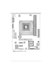
BIOS SATA1 JCMOS 1 SATA 2 SYS_ FAN1 SATA 3 SATA4 4 Motherboard Manual KBMS1 ATXPW R 2 CPU_FAN1 ( H61MGC ) DVI1 VGA1 DDR3_A1 DDR3_B1 Socket 1155 CP U 1 USB1 RJ45USB1 AUDIO1 F_AUDIO1 BAT1 PEX16_1 ATXPW R 1 CODEC PEX1_1 LAN H61 Super I/O PEX1_2 J_COM1 F_USB1 J_ PRINT1 F_USB2 PANEL1 Note: ■ represents the 1st pin.
BIOS SATA1 JCMOS 1 SATA 2 SYS_ FAN1 SATA 3 SATA4 4 Motherboard Manual KBMS1 ATXPW R 2 CPU_FAN1 ( H61MGC ) DVI1 VGA1 DDR3_A1 DDR3_B1 Socket 1155 CP U 1 USB1 RJ45USB1 AUDIO1 F_AUDIO1 BAT1 PEX16_1 ATXPW R 1 CODEC PEX1_1 LAN H61 Super I/O PEX1_2 J_COM1 F_USB1 J_ PRINT1 F_USB2 PANEL1 Note: ■ represents the 1st pin.
Setup Manual
Page 8
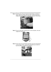
Step 4: Close the load plate. Connect the CPU FAN power cable into the CPU_FAN1 to complete the installation. 6 Align the notches with your thumb and index fingers, oriented as shown. Pressing down without tilting or sliding the processor in the socket. Step 5: Put the CPU Fan and heatsink assembly on the CPU and buckle it on the load plate, close and engage the socket lever. Motherboard Manual Step 3: Hold processor with the socket. Lower the processor straight down on the retention frame.
Step 4: Close the load plate. Connect the CPU FAN power cable into the CPU_FAN1 to complete the installation. 6 Align the notches with your thumb and index fingers, oriented as shown. Pressing down without tilting or sliding the processor in the socket. Step 5: Put the CPU Fan and heatsink assembly on the CPU and buckle it on the load plate, close and engage the socket lever. Motherboard Manual Step 3: Hold processor with the socket. Lower the processor straight down on the retention frame.
Setup Manual
Page 10
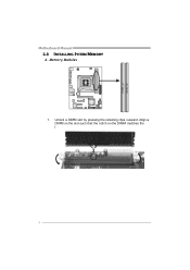
D DR3_A1 DD R3_B1 Motherboard Manual 2.3 INSTALLING SYSTEM MEMORY A. Memory Modules 1. Align a DIMM on the slot such that the notch on the DIMM matches the break on the Slot. 8 Unlock a DIMM slot by pressing the retaining clips outward.
D DR3_A1 DD R3_B1 Motherboard Manual 2.3 INSTALLING SYSTEM MEMORY A. Memory Modules 1. Align a DIMM on the slot such that the notch on the DIMM matches the break on the Slot. 8 Unlock a DIMM slot by pressing the retaining clips outward.
Setup Manual
Page 12
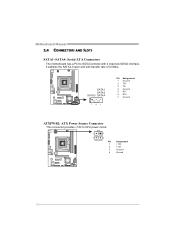
SATA 1 SATA 2 SATA3 SATA4 7 41 Pin Assignment 1 Ground 2 TX+ 3 TX4 Ground 5 RX6 RX+ 7 Ground ATXPWR2: ATX Power Source Connector This connector provides +12V to SATA Controller with 4 channels SATA2 interface, it satisfies the SATA 2.0 spec and with transfer rate of 3.0Gb/s. Motherboard Manual 2.4 CONNECTORS AND SLOTS SATA1~SATA4: Serial ATA Connectors The motherboard has a PCI to CPU power circuit. 2 1 3 4 Pin Assignment 1 +12V 2 +12V 3 Ground 4 Ground 10
SATA 1 SATA 2 SATA3 SATA4 7 41 Pin Assignment 1 Ground 2 TX+ 3 TX4 Ground 5 RX6 RX+ 7 Ground ATXPWR2: ATX Power Source Connector This connector provides +12V to SATA Controller with 4 channels SATA2 interface, it satisfies the SATA 2.0 spec and with transfer rate of 3.0Gb/s. Motherboard Manual 2.4 CONNECTORS AND SLOTS SATA1~SATA4: Serial ATA Connectors The motherboard has a PCI to CPU power circuit. 2 1 3 4 Pin Assignment 1 +12V 2 +12V 3 Ground 4 Ground 10

Setup Manual
Page 14
PCI-Express supports a raw bit-rate of 32GB/s totally. - PCI-Express 3.0 compliant. - PEX1_1: PCI-Express Gen2 x1 Slot - PCI-E 3.0 is supported by Core i7-3xxx / i5-3xxx CPU. Maximum theoretical realized bandwidth of 16GB/s simultaneously per direction; 1GB/s in total. - PCI-Express 2.0 compliant. - PEX16_1 PEX1_1 PEX1_2 12 Motherboard Manual PEX16_1: PCI-Express Gen3 x16 Slot - Data transfer bandwidth up to 500MB/s per direction, for an aggregate of 2.5Gb/s on the data pins.
PCI-Express supports a raw bit-rate of 32GB/s totally. - PCI-Express 3.0 compliant. - PEX1_1: PCI-Express Gen2 x1 Slot - PCI-E 3.0 is supported by Core i7-3xxx / i5-3xxx CPU. Maximum theoretical realized bandwidth of 16GB/s simultaneously per direction; 1GB/s in total. - PCI-Express 2.0 compliant. - PEX16_1 PEX1_1 PEX1_2 12 Motherboard Manual PEX16_1: PCI-Express Gen3 x16 Slot - Data transfer bandwidth up to 500MB/s per direction, for an aggregate of 2.5Gb/s on the data pins.

Setup Manual
Page 16
This header allows only HD audio front panel connector; AC'97 connector is not acceptable. Motherboard Manual F_USB1/F_USB2: Headers for USB 2.0 Ports at Front Panel These headers allow user to connect the front audio output cable with internal USB devices, like ...
This header allows only HD audio front panel connector; AC'97 connector is not acceptable. Motherboard Manual F_USB1/F_USB2: Headers for USB 2.0 Ports at Front Panel These headers allow user to connect the front audio output cable with internal USB devices, like ...
Setup Manual
Page 18
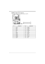
Pin Assignment 1 -Strobe 2 -ALF 3 Data 0 4 -Error 5 Data 1 6 -Init 7 Data 2 8 -Scltin 9 Data 3 10 Ground 11 Data 4 12 Ground 13 Data 5 2 26 1 25 Pin Assignment 14 Ground 15 Data 6 16 Ground 17 Data 7 18 Ground 19 -ACK 20 Ground 21 Busy 22 Ground 23 PE 24 Ground 25 SCLT 26 Key 16 Motherboard Manual J_PRINT1: Printer Port Connector This header allows you to connector printer on the PC.
Pin Assignment 1 -Strobe 2 -ALF 3 Data 0 4 -Error 5 Data 1 6 -Init 7 Data 2 8 -Scltin 9 Data 3 10 Ground 11 Data 4 12 Ground 13 Data 5 2 26 1 25 Pin Assignment 14 Ground 15 Data 6 16 Ground 17 Data 7 18 Ground 19 -ACK 20 Ground 21 Busy 22 Ground 23 PE 24 Ground 25 SCLT 26 Key 16 Motherboard Manual J_PRINT1: Printer Port Connector This header allows you to connector printer on the PC.
Setup Manual
Page 19
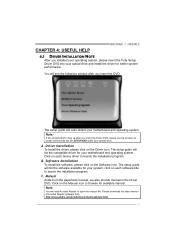
... click on each device driver to launch the installation program. Please download the latest version of Acrobat Reader software from the paperback manual, we also provide manual in the Driver DVD. B. Note: If this window didn't show up after you insert the DVD The setup guide will ... driver, please click on each software title to launch the installation program. Click on the Driver icon. Manual Aside from http://www.adobe.com /produ cts/a crobat /reads tep2 .html 17 H61MGC / H61MLC CHAPTER 4: USEFUL HELP 4.1 DRIVER INSTALLATION NOTE After you insert the Driver DVD, please use ...
... click on each device driver to launch the installation program. Please download the latest version of Acrobat Reader software from the paperback manual, we also provide manual in the Driver DVD. B. Note: If this window didn't show up after you insert the DVD The setup guide will ... driver, please click on each software title to launch the installation program. Click on the Driver icon. Manual Aside from http://www.adobe.com /produ cts/a crobat /reads tep2 .html 17 H61MGC / H61MLC CHAPTER 4: USEFUL HELP 4.1 DRIVER INSTALLATION NOTE After you insert the Driver DVD, please use ...

Setup Manual
Page 20
... on the respective software title. 3. Exi t thi s dialog. Insert the Setup DVD to complete the installation. Double-click the icon to a .txt file 18 Motherboard Manual 4.2 SOFTWARE Installing Software 1.
... on the respective software title. 3. Exi t thi s dialog. Insert the Setup DVD to complete the installation. Double-click the icon to a .txt file 18 Motherboard Manual 4.2 SOFTWARE Installing Software 1.
Setup Manual
Page 22
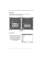
Motherboard Manual BIOS Update BIOS Update is a convenient utility which allows you to save file and enter file name. (We recommend that the file name should be English/number and no longer than 7 characters.) Then click Save. 20 Choose the position to update your motherboard BIOS under Windows system. AWARD BIOS Show current BIOS information AMI BIOS Clear CMOS function (Only for AWARD BIOS) Save current BIOS to a .bin file Update BIOS with a BIOS file Once click on this button, the saving dialog will show.
Motherboard Manual BIOS Update BIOS Update is a convenient utility which allows you to save file and enter file name. (We recommend that the file name should be English/number and no longer than 7 characters.) Then click Save. 20 Choose the position to update your motherboard BIOS under Windows system. AWARD BIOS Show current BIOS information AMI BIOS Clear CMOS function (Only for AWARD BIOS) Save current BIOS to a .bin file Update BIOS with a BIOS file Once click on this button, the saving dialog will show.

Setup Manual
Page 23
... exit BIOS setup. Please do not open dialog will update BIOS with the proper BIOS file, and this process. H61MGC / H61MLC Before doing this, please download the proper BIOS file from this manual. 21 After the BIOS Backup procedure, the open any other applications during this process may be slightly different from...
... exit BIOS setup. Please do not open dialog will update BIOS with the proper BIOS file, and this process. H61MGC / H61MLC Before doing this, please download the proper BIOS file from this manual. 21 After the BIOS Backup procedure, the open any other applications during this process may be slightly different from...
Setup Manual
Page 24
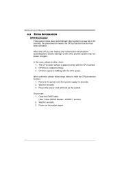
Motherboard Manual 4.3 EXTRA INFORMATION CPU Overheated If the system shuts down automatically after system is powered on for seconds. 3. The CPU cooler surface is fulfilling with the ...
Motherboard Manual 4.3 EXTRA INFORMATION CPU Overheated If the system shuts down automatically after system is powered on for seconds. 3. The CPU cooler surface is fulfilling with the ...

Setup Manual
Page 26
... 1. module snaps into place. Make sure both ends of are running from optical drive. Call the drive manufacturers for compatibility with other drives. 24 Motherboard Manual 4.5 TROUBLESHOOTING Probable Solution 1. Replace cable. System does not boot from an optical 1. All hard disks are securely plugged in setup. fails to disk controller board...
... 1. module snaps into place. Make sure both ends of are running from optical drive. Call the drive manufacturers for compatibility with other drives. 24 Motherboard Manual 4.5 TROUBLESHOOTING Probable Solution 1. Replace cable. System does not boot from an optical 1. All hard disks are securely plugged in setup. fails to disk controller board...
Setup Manual
Page 44
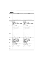
Motherboard Manual JAPANESE H61MGC H61MLC Socket 1155 Socket 1155 Intel Core i7/i5/i3/Pentium/Celeron Intel Core i7/i5/i3/Pentium/Celeron Execute Disable Bit / Enhanced Intel Execute ...
Motherboard Manual JAPANESE H61MGC H61MLC Socket 1155 Socket 1155 Intel Core i7/i5/i3/Pentium/Celeron Intel Core i7/i5/i3/Pentium/Celeron Execute Disable Bit / Enhanced Intel Execute ...

