

I945P-A7 v1.x user's manual
Page 2
... 1: Introduction 1 1.1 Motherboard Features 1 1.2 Package Checklist 6 1.3 Layout and Components 7 Chapter 2: Hardware Installation 8 2.1 Installing Central Processing Unit (CPU 8 2.2 FAN Headers 10 2.3 Installing System Memory 11 2.4 Connectors and Slots 12 Chapter 3: Headers & Jumpers Setup 15 3.1 How to Setup Jumpers 15 3.2 Detail Settings 15 Chapter 4: Useful Help 23 4.1 Award BIOS Beep Code 23 4.2 Extra Information 23 4.3 Troubleshooting 25 Chapter 5: Dual Video Function 26 5.1 Requirements 26 5.2 Installing Graphics Cards 26 5.3 Things...
... 1: Introduction 1 1.1 Motherboard Features 1 1.2 Package Checklist 6 1.3 Layout and Components 7 Chapter 2: Hardware Installation 8 2.1 Installing Central Processing Unit (CPU 8 2.2 FAN Headers 10 2.3 Installing System Memory 11 2.4 Connectors and Slots 12 Chapter 3: Headers & Jumpers Setup 15 3.1 How to Setup Jumpers 15 3.2 Detail Settings 15 Chapter 4: Useful Help 23 4.1 Award BIOS Beep Code 23 4.2 Extra Information 23 4.3 Troubleshooting 25 Chapter 5: Dual Video Function 26 5.1 Requirements 26 5.2 Installing Graphics Cards 26 5.3 Things...
I945P-A7 v1.x user's manual
Page 3
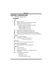
... 2.0). Low Pin Count Interface. I945P-A7 CHAPTER 1: INTRODUCTION 1.1 MOTHERBOARD FEATURES A. Supports Intel Extended Memory 64 Technology (Intel EM64T). Dimensions ATX Form Factor: 24.4cm (W) x 29.7cm (L) Operating System Supporting Supports Windows 2000, and Windows XP. Front Side Bus at the following frequency ranges: 533MT/s (133MHz Core Clock) 800MT/s (200MHz Core Clock) 1066MT/s (266MHz Core Clock) Supports Hyper-Threading Technology. (HT) Supports Execute Disable Bit Technology (XD). Chipset North Bridge: Intel 945P. Hardware CPU Supports LGA 775...
... 2.0). Low Pin Count Interface. I945P-A7 CHAPTER 1: INTRODUCTION 1.1 MOTHERBOARD FEATURES A. Supports Intel Extended Memory 64 Technology (Intel EM64T). Dimensions ATX Form Factor: 24.4cm (W) x 29.7cm (L) Operating System Supporting Supports Windows 2000, and Windows XP. Front Side Bus at the following frequency ranges: 533MT/s (133MHz Core Clock) 800MT/s (200MHz Core Clock) 1066MT/s (266MHz Core Clock) Supports Hyper-Threading Technology. (HT) Supports Execute Disable Bit Technology (XD). Chipset North Bridge: Intel 945P. Hardware CPU Supports LGA 775...
I945P-A7 v1.x user's manual
Page 4
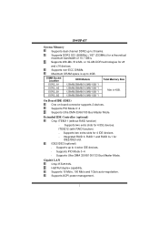
... 10.7 GB/s. I945P-A7 System Memory Supports dual channel DDR2 up to 4 extra IDE devices. Supports PIO Mode 0~4 Supports Ultra DMA 33/66/100/133 Bus Master Mode. Supports 256-Mb, 512-Mb, or 1G-Mb DDR technologies for x8 and x16 devices. Half/Full duplex capability. IDE2/IDE3 (optional) Supports up to 8 banks. Supports 10 Mb/s, 100 Mb/s and 1Gb/s auto-negotiation. Extended IDE Controller (optional) Chip: ITE8211 (without RAID function) -
... 10.7 GB/s. I945P-A7 System Memory Supports dual channel DDR2 up to 4 extra IDE devices. Supports PIO Mode 0~4 Supports Ultra DMA 33/66/100/133 Bus Master Mode. Supports 256-Mb, 512-Mb, or 1G-Mb DDR technologies for x8 and x16 devices. Half/Full duplex capability. IDE2/IDE3 (optional) Supports up to 8 banks. Supports 10 Mb/s, 100 Mb/s and 1Gb/s auto-negotiation. Extended IDE Controller (optional) Chip: ITE8211 (without RAID function) -
I945P-A7 v1.x user's manual
Page 5
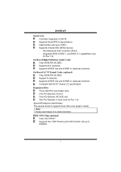
... Advanced Host Controller (AHCI). - Special PCI-Express Dual Feature This special function supports Dual Video (two graphic cards). Supports S/PDIF-Out and S/PDIF-In (optional) functions. On Board AC'97 Sound Codec (optional) Chip: REALTEK ALC655. Integrated RAID 0,RAID 1, and RAID 0+1 capabilities (only for detail information. On Board High Definition Audio Codec Chip: REALTEK ALC882. Two PCI-Express x1 slots (only for Rev 1.0). Supports two 1394 Firewire ports with AC'97 Version 2.3 specification. Supports 4 Serial ATA (SATA) devices. - Supports 8+2 channels.
... Advanced Host Controller (AHCI). - Special PCI-Express Dual Feature This special function supports Dual Video (two graphic cards). Supports S/PDIF-Out and S/PDIF-In (optional) functions. On Board AC'97 Sound Codec (optional) Chip: REALTEK ALC655. Integrated RAID 0,RAID 1, and RAID 0+1 capabilities (only for detail information. On Board High Definition Audio Codec Chip: REALTEK ALC882. Two PCI-Express x1 slots (only for Rev 1.0). Supports two 1394 Firewire ports with AC'97 Version 2.3 specification. Supports 4 Serial ATA (SATA) devices. - Supports 8+2 channels.
I945P-A7 v1.x user's manual
Page 6
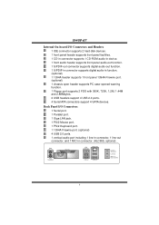
... 4 I945P-A7 Internal On-board I /O Connectors 1 Serial port. 1 Parallel port. 1 Giga LAN jack. 1 PS/2 Mouse port. 1 PS/2 Keyboard port. 1 1394A Firewire port. (optional) 4 USB 2.0 ports. 1 vertical audio port including 1 line-in connector, 1 line-out connector, and 1 MIC-in function. (optional) 1 1394A header supports 1 front panel 1394A Firewire port. (optional) 1 chassis open header supports PC case-opened warning function. 1 Floppy port supports 2 FDD with 360K, 720K, 1.2M, 1.44M and 2.88Mbytes. 2 USB headers support 4 USB 2.0 ports. 4 Serial ATA connectors support 4 SATA devices.
... 4 I945P-A7 Internal On-board I /O Connectors 1 Serial port. 1 Parallel port. 1 Giga LAN jack. 1 PS/2 Mouse port. 1 PS/2 Keyboard port. 1 1394A Firewire port. (optional) 4 USB 2.0 ports. 1 vertical audio port including 1 line-in connector, 1 line-out connector, and 1 MIC-in function. (optional) 1 1394A header supports 1 front panel 1394A Firewire port. (optional) 1 chassis open header supports PC case-opened warning function. 1 Floppy port supports 2 FDD with 360K, 720K, 1.2M, 1.44M and 2.88Mbytes. 2 USB headers support 4 USB 2.0 ports. 4 Serial ATA connectors support 4 SATA devices.
I945P-A7 v1.x user's manual
Page 7
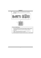
... Codec: 1. I945P-A7 6 audio ports support 8+2 channels audio-out facilities. (ALC882). When rebooting the PC, each port according to default setting. 5 When connecting audio devices into audio ports, the audio driver will be no function. 3. PS/2 Mouse PS/2 Keyboard Parallel COM1 COM1 Giga LAN USB x2 USB x2 Center/Left Rear Side Line-in Line-out MIC-in the system, or all audio ports will auto-detect and pop-up the port function selection window. Please make...
... Codec: 1. I945P-A7 6 audio ports support 8+2 channels audio-out facilities. (ALC882). When rebooting the PC, each port according to default setting. 5 When connecting audio devices into audio ports, the audio driver will be no function. 3. PS/2 Mouse PS/2 Keyboard Parallel COM1 COM1 Giga LAN USB x2 USB x2 Center/Left Rear Side Line-in Line-out MIC-in the system, or all audio ports will auto-detect and pop-up the port function selection window. Please make...
I945P-A7 v1.x user's manual
Page 8
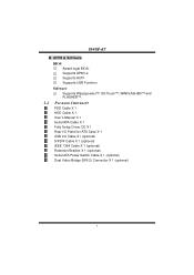
Software Supports Warpspeeder™, 9th Touch™, WINFLASHER™ and FLASHER™. 1.2 PACKAGE CHECKLIST FDD Cable X 1 HDD Cable X 1 User's Manual X 1 Serial ATA Cable X 1 Fully Setup Driver CD X 1 Rear I/O Panel for ATX Case X 1 USB 2.0 Cable X1 (optional) S/PDIF Cable X 1 (optional) IEEE 1394 Cable X 1 (optional) Retention Bracket X 1 (optional) Serial ATA Power Switch Cable X 1 (optional) Dual Video Bridge (BRI-2) Connector X 1 (optional) 6 Supports APM1.2. Supports ACPI Supports USB Function. I945P-A7 B. BIOS & Software BIOS Award legal BIOS.
Software Supports Warpspeeder™, 9th Touch™, WINFLASHER™ and FLASHER™. 1.2 PACKAGE CHECKLIST FDD Cable X 1 HDD Cable X 1 User's Manual X 1 Serial ATA Cable X 1 Fully Setup Driver CD X 1 Rear I/O Panel for ATX Case X 1 USB 2.0 Cable X1 (optional) S/PDIF Cable X 1 (optional) IEEE 1394 Cable X 1 (optional) Retention Bracket X 1 (optional) Serial ATA Power Switch Cable X 1 (optional) Dual Video Bridge (BRI-2) Connector X 1 (optional) 6 Supports APM1.2. Supports ACPI Supports USB Function. I945P-A7 B. BIOS & Software BIOS Award legal BIOS.
I945P-A7 v1.x user's manual
Page 12
The fan cable and connector may be connected to GND. 10 When connecting with Smart Fan Control utility. I945P-A7 2.2 FAN HEADERS These fan headers support cooling-fans built in the computer. JCFAN1: CPU Fan Header JCFAN1 1 4 COM1 Pin Assignment 1 Ground 2 Power 3 FAN RPM rate sense 4 Smart Fan Control Codec JSFAN2: System Fan Header COM1 Pin Assignment 1 Ground 2 +12V 3 FAN RPM rate sense Codec JSFAN2 31 Note: The JCFAN1 supports system cooling fan with wires onto connectors, please note that the red wire is the positive...
The fan cable and connector may be connected to GND. 10 When connecting with Smart Fan Control utility. I945P-A7 2.2 FAN HEADERS These fan headers support cooling-fans built in the computer. JCFAN1: CPU Fan Header JCFAN1 1 4 COM1 Pin Assignment 1 Ground 2 Power 3 FAN RPM rate sense 4 Smart Fan Control Codec JSFAN2: System Fan Header COM1 Pin Assignment 1 Ground 2 +12V 3 FAN RPM rate sense Codec JSFAN2 31 Note: The JCFAN1 supports system cooling fan with wires onto connectors, please note that the red wire is the positive...
I945P-A7 v1.x user's manual
Page 14
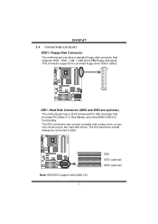
...This connector supports the provided floppy drive ribbon cables. 34 33 COM1 2 1 Codec IDE1: Hard Disk Connector (IDE2 and IDE3 are optional.) The motherboard has a 32-bit Enhanced PCI IDE Controller that supports 360K, 720K, 1.2M, 1.44M and 2.88M floppy disk types. The IDE connectors can connect a master and a slave drive, so you can connect up to IDE1. The first hard drive should always be connected to two hard disk drives. I945P-A7 2.4 CONNECTORS AND SLOTS FDD1: Floppy Disk Connector The motherboard provides a standard floppy disk connector that provides PIO Mode 0~4, Bus...
...This connector supports the provided floppy drive ribbon cables. 34 33 COM1 2 1 Codec IDE1: Hard Disk Connector (IDE2 and IDE3 are optional.) The motherboard has a 32-bit Enhanced PCI IDE Controller that supports 360K, 720K, 1.2M, 1.44M and 2.88M floppy disk types. The IDE connectors can connect a master and a slave drive, so you can connect up to IDE1. The first hard drive should always be connected to two hard disk drives. I945P-A7 2.4 CONNECTORS AND SLOTS FDD1: Floppy Disk Connector The motherboard provides a standard floppy disk connector that provides PIO Mode 0~4, Bus...
I945P-A7 v1.x user's manual
Page 15
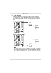
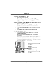
... transfer is compliant with PCI-E x4 and PCI-E x1 expansion card. - Data transfer bandwidth up to 250MB/s per direction, and for PCI-Express interface graphic cards. - PCI-Express 1.0a compliant. - PCI-Ex16 PCI-Ex1_1 (for v1.0) PCI-Ex1_2 (for Rev 1.0) - PCI-Express supports a raw bit-rate of 2.5Gb/s on the data pins. - 2X bandwidth over the traditional PCI architecture. PCI-Extreme slot is compatible with PCI-Express 1.0a specification. - I945P-A7 PCI-Ex16: PCI-Express x16 Slot - PCI-Extreme slot is a special design...
... transfer is compliant with PCI-E x4 and PCI-E x1 expansion card. - Data transfer bandwidth up to 250MB/s per direction, and for PCI-Express interface graphic cards. - PCI-Express 1.0a compliant. - PCI-Ex16 PCI-Ex1_1 (for v1.0) PCI-Ex1_2 (for Rev 1.0) - PCI-Express supports a raw bit-rate of 2.5Gb/s on the data pins. - 2X bandwidth over the traditional PCI architecture. PCI-Extreme slot is compatible with PCI-Express 1.0a specification. - I945P-A7 PCI-Ex16: PCI-Express x16 Slot - PCI-Extreme slot is a special design...
I945P-A7 v1.x user's manual
Page 17
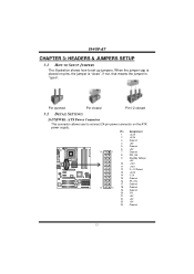
... 9 Standby Voltage +5V 10 +12V 11 +12V 12 2 x 12 Detect 13 +3.3V 14 -12V 15 Ground Codec 16 PS_ON 17 Ground 24 12 18 Ground 19 Ground 20 -5V 21 +5V 22 +5V 23 +5V 24 Ground 15 I945P-A7 CHAPTER 3: HEADERS & JUMPERS SETUP 3.1 HOW TO SETUP JUMPERS The illustration shows how to connect 24-pin power connector on pins, the jumper is "close...
... 9 Standby Voltage +5V 10 +12V 11 +12V 12 2 x 12 Detect 13 +3.3V 14 -12V 15 Ground Codec 16 PS_ON 17 Ground 24 12 18 Ground 19 Ground 20 -5V 21 +5V 22 +5V 23 +5V 24 Ground 15 I945P-A7 CHAPTER 3: HEADERS & JUMPERS SETUP 3.1 HOW TO SETUP JUMPERS The illustration shows how to connect 24-pin power connector on pins, the jumper is "close...

I945P-A7 v1.x user's manual
Page 19
I945P-A7 J1394A1 (optional): Header for 1394 Firewire Port at Front Panel COM1 Pin Assignment 1 A+ 2 A- 3 Ground 4 Ground 5 B+ 6 B- 7 +12V 8 +12V Codec 2 10 9 Key 10 Ground 1 9 J1394PWR1 (optional): Power Source for 1394 chipset. JCDIN1: CD-ROM Audio-in Connector This connector allows user to connect the digital image device, like CD-ROM, DVD-ROM, PCI sound card, PCI TV turner card etc.. COM1 13 Pin 1-2 Close +3.3V for 1394 chipset. (Default) 13 Pin 2-3 close Codec 13 +3.3V SB for 1394 Firewire Port This header allows...
I945P-A7 J1394A1 (optional): Header for 1394 Firewire Port at Front Panel COM1 Pin Assignment 1 A+ 2 A- 3 Ground 4 Ground 5 B+ 6 B- 7 +12V 8 +12V Codec 2 10 9 Key 10 Ground 1 9 J1394PWR1 (optional): Power Source for 1394 chipset. JCDIN1: CD-ROM Audio-in Connector This connector allows user to connect the digital image device, like CD-ROM, DVD-ROM, PCI sound card, PCI TV turner card etc.. COM1 13 Pin 1-2 Close +3.3V for 1394 chipset. (Default) 13 Pin 2-3 close Codec 13 +3.3V SB for 1394 Firewire Port This header allows...
I945P-A7 v1.x user's manual
Page 21
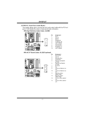
I945P-A7 JAUDIOF1: Front Panel Audio Header This header allows user to connect the front audio output cable with the PC front panel. It will disable the output on back panel audio connectors. With High Definition Audio Codec: ALC882 COM1 Pin Assignment 1 Mic (L) 2 Ground 10 9 3 Mic (R) 4 PRESENCE 5 Headphone (R) 6 Jack 1 SENSE 7 Jack Detection 2 1 8 Connector Key Codec 9 Headphone (L) 10 Jack 2 SENSE With AC'97 Sound Codec: ALC655 (optional) Pin 1 2 3 4 5 COM1 6 14 13 7 8 9 10 2 1 Codec 11 12...
I945P-A7 JAUDIOF1: Front Panel Audio Header This header allows user to connect the front audio output cable with the PC front panel. It will disable the output on back panel audio connectors. With High Definition Audio Codec: ALC882 COM1 Pin Assignment 1 Mic (L) 2 Ground 10 9 3 Mic (R) 4 PRESENCE 5 Headphone (R) 6 Jack 1 SENSE 7 Jack Detection 2 1 8 Connector Key Codec 9 Headphone (L) 10 Jack 2 SENSE With AC'97 Sound Codec: ALC655 (optional) Pin 1 2 3 4 5 COM1 6 14 13 7 8 9 10 2 1 Codec 11 12...

I945P-A7 v1.x user's manual
Page 23
... JPANEL1: Front Panel Header This 24-pin connector includes Power-on button IrDA Connector 21 COM1 Codec Pin Assignment 1 +5V 3 N/A 5 N/A 7 Speaker 9 HDD LED (+) 11 HDD LED (-) 13 Ground 15 Reset control 17 N/A 19 N/A 21 +5V 23 IRTX 24 23 IR IR On/Off PWR_LED SLP ++ +- I945P-A7 SATA1~SATA4: Serial ATA Connectors The motherboard has a PCI to connect the PC case's front panel switch functions. It allows user to SATA Controller with 4 channels SATA interface, it satisfies the SATA 2.0 spec and with...
... JPANEL1: Front Panel Header This 24-pin connector includes Power-on button IrDA Connector 21 COM1 Codec Pin Assignment 1 +5V 3 N/A 5 N/A 7 Speaker 9 HDD LED (+) 11 HDD LED (-) 13 Ground 15 Reset control 17 N/A 19 N/A 21 +5V 23 IRTX 24 23 IR IR On/Off PWR_LED SLP ++ +- I945P-A7 SATA1~SATA4: Serial ATA Connectors The motherboard has a PCI to connect the PC case's front panel switch functions. It allows user to SATA Controller with 4 channels SATA interface, it satisfies the SATA 2.0 spec and with...

I945P-A7 v1.x user's manual
Page 24
...; Clear CMOS Procedures: 1. Remove AC power line. 2. Set the jumper to the CMOS and show the message on next boot-up. JCI1: Chassis Open Header This connector allows system to "Pin 2-3 close ". 5. COM1 Pin Assignment 1 Case open status. Wait for five seconds. 4. Power on pin2-3, it will record to "Pin 1-2 close ". 3. Set the jumper to monitor PC case open signal 2 Ground 2 1 Codec 22 Reset your desired password or clear the CMOS data. I945P-A7 JCMOS1: Clear CMOS Header By...
...; Clear CMOS Procedures: 1. Remove AC power line. 2. Set the jumper to the CMOS and show the message on next boot-up. JCI1: Chassis Open Header This connector allows system to "Pin 2-3 close ". 5. COM1 Pin Assignment 1 Case open status. Wait for five seconds. 4. Power on pin2-3, it will record to "Pin 1-2 close ". 3. Set the jumper to monitor PC case open signal 2 Ground 2 1 Codec 22 Reset your desired password or clear the CMOS data. I945P-A7 JCMOS1: Clear CMOS Header By...
I945P-A7 v1.x user's manual
Page 25
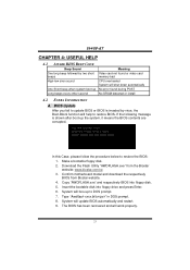
... boot-up Long beeps every other second Meaning Video card not found or video card memory bad CPU overheated System will shut down automatically No error found during POST No DRAM detected or install 4.2 EXTRA INFORMATION A. In this Case, please follow the procedure below to DOS prompt. 7. Make a bootable floppy disk. 2. System will boo-up to restore the BIOS: 1. Copy "AWDFLASH.exe" and respectively BIOS into floppy drive and press Enter. 6. Download...
... boot-up Long beeps every other second Meaning Video card not found or video card memory bad CPU overheated System will shut down automatically No error found during POST No DRAM detected or install 4.2 EXTRA INFORMATION A. In this Case, please follow the procedure below to DOS prompt. 7. Make a bootable floppy disk. 2. System will boo-up to restore the BIOS: 1. Copy "AWDFLASH.exe" and respectively BIOS into floppy drive and press Enter. 6. Download...

I945P-A7 v1.x user's manual
Page 27
... using backup disks. Call the drive manufacturers for compatibility with other drives. 25 Contact technical support. 2. System does not boot from optical drive. 1. Cannot boot system after installing second hard drive. 1. Keyboard lights are on keyboard does not turn 2. check the drive type in ; Hard disk can be read and applications can be used but booting from disk to the system at any time. I945P-A7 4.3 TROUBLESHOOTING Probable Solution 1. Make sure power cable is Power light don't illuminate, fan securely plugged in setup...
... using backup disks. Call the drive manufacturers for compatibility with other drives. 25 Contact technical support. 2. System does not boot from optical drive. 1. Cannot boot system after installing second hard drive. 1. Keyboard lights are on keyboard does not turn 2. check the drive type in ; Hard disk can be read and applications can be used but booting from disk to the system at any time. I945P-A7 4.3 TROUBLESHOOTING Probable Solution 1. Make sure power cable is Power light don't illuminate, fan securely plugged in setup...

I945P-A7 v1.x user's manual
Page 28
... the system will be unstable. 5.2 INSTALLING GRAPHICS CARDS Step 1: Prepare two graphics cards with PCI-E x16 interface. I945P-A7 CHAPTER 5: DUAL VIDEO FUNCTION Note: Dual Video Function is only for Rev 1.0. Two identical graphics cards that are only for Rev 1.0. 5.1 REQUIREMENTS Only Windows XP supports Dual Video function. Step 4: Insert the Dual Video Bridge (BRI-2) connector on the gold-fingers on each graphics card. 26 Step 3: Insert the second graphics card into the white slot (PCI-EX).
... the system will be unstable. 5.2 INSTALLING GRAPHICS CARDS Step 1: Prepare two graphics cards with PCI-E x16 interface. I945P-A7 CHAPTER 5: DUAL VIDEO FUNCTION Note: Dual Video Function is only for Rev 1.0. Two identical graphics cards that are only for Rev 1.0. 5.1 REQUIREMENTS Only Windows XP supports Dual Video function. Step 4: Insert the Dual Video Bridge (BRI-2) connector on the gold-fingers on each graphics card. 26 Step 3: Insert the second graphics card into the white slot (PCI-EX).

I945P-A7 v1.x user's manual
Page 29
... are NVIDIA certified. Coordinate with a screw. Step 5-2: Align and insert the retention bracket into the slot and then fix it with graphics card driver to set Dual Video function. 27 Dual Video Mode: Use Dual Video Bridge (BRI-2) connector to link two identical PCI-E x16 interface graphics cards that are optional. 5.3 THINGS TO NOTICE Normal Mode: Only PCI-Ex16 slot supports PCI-Express x16 interface graphics card function. PCI-EX slot supports PCI-Express x4 interface expansion...
... are NVIDIA certified. Coordinate with a screw. Step 5-2: Align and insert the retention bracket into the slot and then fix it with graphics card driver to set Dual Video function. 27 Dual Video Mode: Use Dual Video Bridge (BRI-2) connector to link two identical PCI-E x16 interface graphics cards that are optional. 5.3 THINGS TO NOTICE Normal Mode: Only PCI-Ex16 slot supports PCI-Express x16 interface graphics card function. PCI-EX slot supports PCI-Express x4 interface expansion...
I945P-A7 v1.x user's manual
Page 30
... OS Support: Windows 98 SE, Windows Me, Windows 2000, Windows XP DirectX: DirectX 8.1 or above. (The Windows XP operating system includes DirectX 8.1. Moreover, to install DirectX 8.1.) 28 I945P-A7 CHAPTER 6: WARPSPEEDER™ 6.1 INTRODUCTION [WarpSpeeder™], a new powerful control utility, features three user-friendly functions including Overclock Manager, Overvoltage Manager, and Hardware Monitor. The cool Hardware Monitor smartly indicates the temperatures, voltage and CPU fan speed as well as the chipset information. If you use Windows...
... OS Support: Windows 98 SE, Windows Me, Windows 2000, Windows XP DirectX: DirectX 8.1 or above. (The Windows XP operating system includes DirectX 8.1. Moreover, to install DirectX 8.1.) 28 I945P-A7 CHAPTER 6: WARPSPEEDER™ 6.1 INTRODUCTION [WarpSpeeder™], a new powerful control utility, features three user-friendly functions including Overclock Manager, Overvoltage Manager, and Hardware Monitor. The cool Hardware Monitor smartly indicates the temperatures, voltage and CPU fan speed as well as the chipset information. If you use Windows...


