

I945P-A7 v1.x user's manual
Page 2
... 1: Introduction 1 1.1 Motherboard Features 1 1.2 Package Checklist 6 1.3 Layout and Components 7 Chapter 2: Hardware Installation 8 2.1 Installing Central Processing Unit (CPU 8 2.2 FAN Headers 10 2.3 Installing System Memory 11 2.4 Connectors and Slots 12 Chapter 3: Headers & Jumpers Setup 15 3.1 How to Setup Jumpers 15 3.2 Detail Settings 15 Chapter 4: Useful Help 23 4.1 Award BIOS Beep Code 23 4.2 Extra Information 23 4.3 Troubleshooting 25 Chapter 5: Dual Video Function 26 5.1 Requirements 26 5.2 Installing Graphics Cards 26 5.3 Things...
... 1: Introduction 1 1.1 Motherboard Features 1 1.2 Package Checklist 6 1.3 Layout and Components 7 Chapter 2: Hardware Installation 8 2.1 Installing Central Processing Unit (CPU 8 2.2 FAN Headers 10 2.3 Installing System Memory 11 2.4 Connectors and Slots 12 Chapter 3: Headers & Jumpers Setup 15 3.1 How to Setup Jumpers 15 3.2 Detail Settings 15 Chapter 4: Useful Help 23 4.1 Award BIOS Beep Code 23 4.2 Extra Information 23 4.3 Troubleshooting 25 Chapter 5: Dual Video Function 26 5.1 Requirements 26 5.2 Installing Graphics Cards 26 5.3 Things...
I945P-A7 v1.x user's manual
Page 3
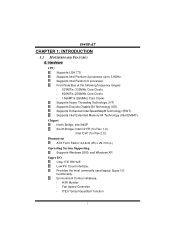
... Core Clock) Supports Hyper-Threading Technology. (HT) Supports Execute Disable Bit Technology (XD). Provides the most commonly used legacy Super I /O Chip: ITE IT8712F. Supports Intel Pentium D processor. Chipset North Bridge: Intel 945P. Super I /O functionality. Environment Control initiatives, H/W Monitor Fan Speed Controller ITE's "Smart Guardian" function 1 Intel ICH7 (for Rev 1.0). South Bridge: Intel ICH7R (for Rev 2.0). Supports Intel Pentium 4 processor up to 3.8GHz. I945P-A7 CHAPTER 1: INTRODUCTION 1.1 MOTHERBOARD FEATURES A. Supports Enhanced...
... Core Clock) Supports Hyper-Threading Technology. (HT) Supports Execute Disable Bit Technology (XD). Provides the most commonly used legacy Super I /O Chip: ITE IT8712F. Supports Intel Pentium D processor. Chipset North Bridge: Intel 945P. Super I /O functionality. Environment Control initiatives, H/W Monitor Fan Speed Controller ITE's "Smart Guardian" function 1 Intel ICH7 (for Rev 1.0). South Bridge: Intel ICH7R (for Rev 2.0). Supports Intel Pentium 4 processor up to 3.8GHz. I945P-A7 CHAPTER 1: INTRODUCTION 1.1 MOTHERBOARD FEATURES A. Supports Enhanced...
I945P-A7 v1.x user's manual
Page 4
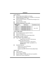
... Socket Location DDR Module Total Memory Size DDR2_A1 128MB/256MB/512MB/1GB *1 DDR2_A2 DDR2_B1 128MB/256MB/512MB/1GB *1 128MB/256MB/512MB/1GB *1 Max is up to 8 banks. Supports DDR2 533 (266MHz) / 667 (333MHz) for 4 IDE devices - Integrated RAID 0, RAID 1 and RAID 0+1 for IDE2/IDE3 slot. Supports non-ECC DIMMs. Maximum DRAM space is 4GB. Half/Full duplex capability. I945P-A7 System Memory Supports dual channel DDR2 up to 4 extra IDE devices. Supports...
... Socket Location DDR Module Total Memory Size DDR2_A1 128MB/256MB/512MB/1GB *1 DDR2_A2 DDR2_B1 128MB/256MB/512MB/1GB *1 128MB/256MB/512MB/1GB *1 Max is up to 8 banks. Supports DDR2 533 (266MHz) / 667 (333MHz) for 4 IDE devices - Integrated RAID 0, RAID 1 and RAID 0+1 for IDE2/IDE3 slot. Supports non-ECC DIMMs. Maximum DRAM space is 4GB. Half/Full duplex capability. I945P-A7 System Memory Supports dual channel DDR2 up to 4 extra IDE devices. Supports...
I945P-A7 v1.x user's manual
Page 5
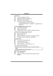
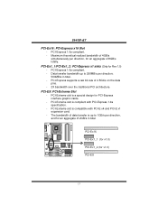
...) slot. Special PCI-Express Dual Feature This special function supports Dual Video (two graphic cards). Support 6 channels. Expansion Slots Three 32bit PCI bus master slots. IEEE 1394 Chip (optional) Chip: VIA VT6307. Supports Serial ATA 2.0 specification. Integrated RAID 0,RAID 1, and RAID 0+1 capabilities (only for Rev 1.0). Supports two 1394 Firewire ports with AC'97 Version 2.3 specification. I945P-A7 Serial ATA Controller integrated in ICH7R. One PCI-Express x16 slot. On Board High Definition Audio Codec Chip: REALTEK ALC882. Supports 8+2 channels. Supports 4 Serial ATA (SATA...
...) slot. Special PCI-Express Dual Feature This special function supports Dual Video (two graphic cards). Support 6 channels. Expansion Slots Three 32bit PCI bus master slots. IEEE 1394 Chip (optional) Chip: VIA VT6307. Supports Serial ATA 2.0 specification. Integrated RAID 0,RAID 1, and RAID 0+1 capabilities (only for Rev 1.0). Supports two 1394 Firewire ports with AC'97 Version 2.3 specification. I945P-A7 Serial ATA Controller integrated in ICH7R. One PCI-Express x16 slot. On Board High Definition Audio Codec Chip: REALTEK ALC882. Supports 8+2 channels. Supports 4 Serial ATA (SATA...
I945P-A7 v1.x user's manual
Page 6
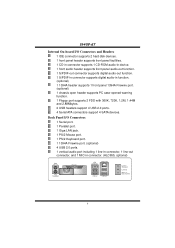
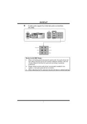
...Center 4 I945P-A7 Internal On-board I /O Connectors 1 Serial port. 1 Parallel port. 1 Giga LAN jack. 1 PS/2 Mouse port. 1 PS/2 Keyboard port. 1 1394A Firewire port. (optional) 4 USB 2.0 ports. 1 vertical audio port including 1 line-in connector, 1 line-out connector, and 1 MIC-in function. (optional) 1 1394A header supports 1 front panel 1394A Firewire port. (optional) 1 chassis open header supports PC case-opened warning function. 1 Floppy port supports 2 FDD with 360K, 720K, 1.2M, 1.44M and 2.88Mbytes. 2 USB headers support 4 USB 2.0 ports. 4 Serial ATA connectors support 4 SATA devices.
...Center 4 I945P-A7 Internal On-board I /O Connectors 1 Serial port. 1 Parallel port. 1 Giga LAN jack. 1 PS/2 Mouse port. 1 PS/2 Keyboard port. 1 1394A Firewire port. (optional) 4 USB 2.0 ports. 1 vertical audio port including 1 line-in connector, 1 line-out connector, and 1 MIC-in function. (optional) 1 1394A header supports 1 front panel 1394A Firewire port. (optional) 1 chassis open header supports PC case-opened warning function. 1 Floppy port supports 2 FDD with 360K, 720K, 1.2M, 1.44M and 2.88Mbytes. 2 USB headers support 4 USB 2.0 ports. 4 Serial ATA connectors support 4 SATA devices.
I945P-A7 v1.x user's manual
Page 7
When connecting audio devices into audio ports, the audio driver will be no function. 3. User can choose different functions for ALC882 Codec: 1. Please make sure the audio driver is successful installed in Notice for each port function will return to personal preference. 2. When rebooting the PC, each port according to default setting. 5 I945P-A7 6 audio ports support 8+2 channels audio-out facilities. (ALC882). PS/2 Mouse PS/2 Keyboard Parallel COM1 COM1 Giga LAN USB x2 USB x2 Center/Left Rear...
When connecting audio devices into audio ports, the audio driver will be no function. 3. User can choose different functions for ALC882 Codec: 1. Please make sure the audio driver is successful installed in Notice for each port function will return to personal preference. 2. When rebooting the PC, each port according to default setting. 5 I945P-A7 6 audio ports support 8+2 channels audio-out facilities. (ALC882). PS/2 Mouse PS/2 Keyboard Parallel COM1 COM1 Giga LAN USB x2 USB x2 Center/Left Rear...
I945P-A7 v1.x user's manual
Page 8
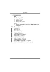
Supports ACPI Supports USB Function. Software Supports Warpspeeder™, 9th Touch™, WINFLASHER™ and FLASHER™. 1.2 PACKAGE CHECKLIST FDD Cable X 1 HDD Cable X 1 User's Manual X 1 Serial ATA Cable X 1 Fully Setup Driver CD X 1 Rear I/O Panel for ATX Case X 1 USB 2.0 Cable X1 (optional) S/PDIF Cable X 1 (optional) IEEE 1394 Cable X 1 (optional) Retention Bracket X 1 (optional) Serial ATA Power Switch Cable X 1 (optional) Dual Video Bridge (BRI-2) Connector X 1 (optional) 6 BIOS & Software BIOS Award legal BIOS. Supports APM1.2. I945P-A7 B.
Supports ACPI Supports USB Function. Software Supports Warpspeeder™, 9th Touch™, WINFLASHER™ and FLASHER™. 1.2 PACKAGE CHECKLIST FDD Cable X 1 HDD Cable X 1 User's Manual X 1 Serial ATA Cable X 1 Fully Setup Driver CD X 1 Rear I/O Panel for ATX Case X 1 USB 2.0 Cable X1 (optional) S/PDIF Cable X 1 (optional) IEEE 1394 Cable X 1 (optional) Retention Bracket X 1 (optional) Serial ATA Power Switch Cable X 1 (optional) Dual Video Bridge (BRI-2) Connector X 1 (optional) 6 BIOS & Software BIOS Award legal BIOS. Supports APM1.2. I945P-A7 B.
I945P-A7 v1.x user's manual
Page 12
... JCFAN1 supports system cooling fan with wires onto connectors, please note that the red wire is the positive and should be connected to pin#2, and the black wire is Ground and should be different according to pin#1. Connect the fan cable to the connector while matching the black wire to the fan manufacturer. It supports 4-pin head connector. I945P-A7 2.2 FAN HEADERS These fan headers support cooling-fans built in the computer. The fan cable and connector may be connected...
... JCFAN1 supports system cooling fan with wires onto connectors, please note that the red wire is the positive and should be connected to pin#2, and the black wire is Ground and should be different according to pin#1. Connect the fan cable to the connector while matching the black wire to the fan manufacturer. It supports 4-pin head connector. I945P-A7 2.2 FAN HEADERS These fan headers support cooling-fans built in the computer. The fan cable and connector may be connected...
I945P-A7 v1.x user's manual
Page 14
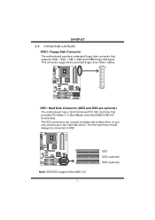
... Mode 0~4, Bus Master, and Ultra DMA 33/66/100 functionality. The IDE connectors can connect a master and a slave drive, so you can connect up to IDE1. COM1 39 Codec 40 Note: IDE2/IDE3 support Ultra DMA 133. 12 1 IDE1 IDE3 (optional) 2 IDE2 (optional) This connector supports the provided floppy drive ribbon cables. 34 33 COM1 2 1 Codec IDE1: Hard Disk Connector (IDE2 and IDE3 are optional.) The motherboard has a 32-bit Enhanced PCI IDE Controller...
... Mode 0~4, Bus Master, and Ultra DMA 33/66/100 functionality. The IDE connectors can connect a master and a slave drive, so you can connect up to IDE1. COM1 39 Codec 40 Note: IDE2/IDE3 support Ultra DMA 133. 12 1 IDE1 IDE3 (optional) 2 IDE2 (optional) This connector supports the provided floppy drive ribbon cables. 34 33 COM1 2 1 Codec IDE1: Hard Disk Connector (IDE2 and IDE3 are optional.) The motherboard has a 32-bit Enhanced PCI IDE Controller...
I945P-A7 v1.x user's manual
Page 15
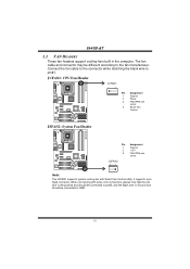
... total. - PCI-Express 1.0a compliant. - PCI-Extreme slot is compatible with PCI-Express 1.0a specification. - The bandwidth of data transfer is compliant with PCI-E x4 and PCI-E x1 expansion card. - PCI-Ex16 PCI-Ex1_1 (for v1.0) PCI-Ex1_2 (for Rev 1.0) - PCI-Extreme slot is a special design for an aggregate of 2.5Gb/s on the data pins. - 2X bandwidth over the traditional PCI architecture. PCI-EX: PCI-Extreme Slot - I945P-A7 PCI-Ex16: PCI-Express x16 Slot - Data transfer...
... total. - PCI-Express 1.0a compliant. - PCI-Extreme slot is compatible with PCI-Express 1.0a specification. - The bandwidth of data transfer is compliant with PCI-E x4 and PCI-E x1 expansion card. - PCI-Ex16 PCI-Ex1_1 (for v1.0) PCI-Ex1_2 (for Rev 1.0) - PCI-Extreme slot is a special design for an aggregate of 2.5Gb/s on the data pins. - 2X bandwidth over the traditional PCI architecture. PCI-EX: PCI-Extreme Slot - I945P-A7 PCI-Ex16: PCI-Express x16 Slot - Data transfer...
I945P-A7 v1.x user's manual
Page 17
... 19 Ground 20 -5V 21 +5V 22 +5V 23 +5V 24 Ground 15 I945P-A7 CHAPTER 3: HEADERS & JUMPERS SETUP 3.1 HOW TO SETUP JUMPERS The illustration shows how to connect 24-pin power connector on pins, the jumper is "close", if not, that means the jumper is placed on the ATX power supply. Pin opened Pin closed Pin1-2 closed 3.2 DETAIL SETTINGS JATXPWR1: ATX Power Connector This connector allows user to set up jumpers. When the jumper cap is "open".
... 19 Ground 20 -5V 21 +5V 22 +5V 23 +5V 24 Ground 15 I945P-A7 CHAPTER 3: HEADERS & JUMPERS SETUP 3.1 HOW TO SETUP JUMPERS The illustration shows how to connect 24-pin power connector on pins, the jumper is "close", if not, that means the jumper is placed on the ATX power supply. Pin opened Pin closed Pin1-2 closed 3.2 DETAIL SETTINGS JATXPWR1: ATX Power Connector This connector allows user to set up jumpers. When the jumper cap is "open".

I945P-A7 v1.x user's manual
Page 19
... user to connect the audio source from the variety devices, like DV, D8, or V8, etc. JCDIN1: CD-ROM Audio-in Connector This connector allows user to connect the digital image device, like CD-ROM, DVD-ROM, PCI sound card, PCI TV turner card etc.. COM1 Pin Assignment 1 Left channel input 2 Ground 3 Ground 17 I945P-A7 J1394A1 (optional): Header for 1394 Firewire Port at Front Panel COM1 Pin Assignment 1 A+ 2 A- 3 Ground 4 Ground 5 B+ 6 B- 7 +12V 8 +12V Codec 2 10 9 Key 10 Ground 1 9 J1394PWR1 (optional): Power...
... user to connect the audio source from the variety devices, like DV, D8, or V8, etc. JCDIN1: CD-ROM Audio-in Connector This connector allows user to connect the digital image device, like CD-ROM, DVD-ROM, PCI sound card, PCI TV turner card etc.. COM1 Pin Assignment 1 Left channel input 2 Ground 3 Ground 17 I945P-A7 J1394A1 (optional): Header for 1394 Firewire Port at Front Panel COM1 Pin Assignment 1 A+ 2 A- 3 Ground 4 Ground 5 B+ 6 B- 7 +12V 8 +12V Codec 2 10 9 Key 10 Ground 1 9 J1394PWR1 (optional): Power...

I945P-A7 v1.x user's manual
Page 22
... USB Headers This motherboard provides 2 USB 2.0 headers, which allows user to support this function "Power-on system via keyboard and mouse", "JKBV1" jumper cap should be placed on the PC front panel, and also can be connected with internal USB devices, like USB card reader. Note: In order to connect additional USB cable on Pin 2-3. I945P-A7 JKBV1: Power Source Header for PS/2 Keyboard and Mouse COM1 3 3 1 Pin 1-2 Close 1 +5V for PS/2 keyboard and mouse. 3 Codec 1 Pin 2-3 close PS/2 keyboard...
... USB Headers This motherboard provides 2 USB 2.0 headers, which allows user to support this function "Power-on system via keyboard and mouse", "JKBV1" jumper cap should be placed on the PC front panel, and also can be connected with internal USB devices, like USB card reader. Note: In order to connect additional USB cable on Pin 2-3. I945P-A7 JKBV1: Power Source Header for PS/2 Keyboard and Mouse COM1 3 3 1 Pin 1-2 Close 1 +5V for PS/2 keyboard and mouse. 3 Codec 1 Pin 2-3 close PS/2 keyboard...

I945P-A7 v1.x user's manual
Page 23
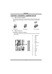
... Pin Assignment 2 Sleep control Speaker Connector 4 Ground 6 N/A 8 Power LED (+) Hard drive LED 10 Power LED (+) 12 Power LED (-) Reset button 14 Power button 16 Ground 18 Key IrDA Connector 20 Key 22 Ground 24 IRRX Function Sleep button N/A Power LED Power-on , Reset, HDD LED, Power LED, Sleep button, speaker and IrDA Connection. I945P-A7 SATA1~SATA4: Serial ATA Connectors The motherboard has a PCI to connect the PC case's front panel switch functions. COM1 Codec Pin Assignment 1 +5V 3 N/A 5 N/A 7 Speaker 9 HDD LED (+) 11 HDD LED (-) 13 Ground 15 Reset control...
... Pin Assignment 2 Sleep control Speaker Connector 4 Ground 6 N/A 8 Power LED (+) Hard drive LED 10 Power LED (+) 12 Power LED (-) Reset button 14 Power button 16 Ground 18 Key IrDA Connector 20 Key 22 Ground 24 IRRX Function Sleep button N/A Power LED Power-on , Reset, HDD LED, Power LED, Sleep button, speaker and IrDA Connection. I945P-A7 SATA1~SATA4: Serial ATA Connectors The motherboard has a PCI to connect the PC case's front panel switch functions. COM1 Codec Pin Assignment 1 +5V 3 N/A 5 N/A 7 Speaker 9 HDD LED (+) 11 HDD LED (-) 13 Ground 15 Reset control...

I945P-A7 v1.x user's manual
Page 24
...: Chassis Open Header This connector allows system to the CMOS and show the message on next boot-up. Remove AC power line. 2. Set the jumper to "Pin 2-3 close ". 5. Reset your desired password or clear the CMOS data. If the signal has been triggered, it allows user to restore the BIOS safe setting and the CMOS data, please carefully follow the procedures to "Pin 1-2 close ". 3. Set the jumper to avoid damaging the motherboard. 1 COM1 3 Pin...
...: Chassis Open Header This connector allows system to the CMOS and show the message on next boot-up. Remove AC power line. 2. Set the jumper to "Pin 2-3 close ". 5. Reset your desired password or clear the CMOS data. If the signal has been triggered, it allows user to restore the BIOS safe setting and the CMOS data, please carefully follow the procedures to "Pin 1-2 close ". 3. Set the jumper to avoid damaging the motherboard. 1 COM1 3 Pin...
I945P-A7 v1.x user's manual
Page 25
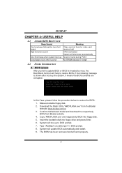
... the system, it means the BIOS contents are corrupted. System will help to restore the BIOS: 1. Make a bootable floppy disk. 2. The BIOS has been recovered and will shut down automatically No error found during POST No DRAM detected or install 4.2 EXTRA INFORMATION A. I945P-A7 CHAPTER 4: USEFUL HELP 4.1 AWARD BIOS BEEP CODE Beep Sound One long beep followed by virus, the Boot-Block function will update BIOS automatically and restart. 9. Type "Awdflash xxxx.bf/sn...
... the system, it means the BIOS contents are corrupted. System will help to restore the BIOS: 1. Make a bootable floppy disk. 2. The BIOS has been recovered and will shut down automatically No error found during POST No DRAM detected or install 4.2 EXTRA INFORMATION A. I945P-A7 CHAPTER 4: USEFUL HELP 4.1 AWARD BIOS BEEP CODE Beep Sound One long beep followed by virus, the Boot-Block function will update BIOS automatically and restart. 9. Type "Awdflash xxxx.bf/sn...

I945P-A7 v1.x user's manual
Page 27
... and select correct drive types. Make sure power cable is impossible. System inoperative. is Power light don't illuminate, fan securely plugged in setup. Review system's equipment. System does not boot from optical drive. 1. Re-install applications and data using backup disks. I945P-A7 4.3 TROUBLESHOOTING Probable Solution 1. Reformat the hard drive. Cannot boot system after installing second hard drive. 1. on both ends are on . Call the drive manufacturers for compatibility with other drives. 25 No power to disk controller board.
... and select correct drive types. Make sure power cable is impossible. System inoperative. is Power light don't illuminate, fan securely plugged in setup. Review system's equipment. System does not boot from optical drive. 1. Re-install applications and data using backup disks. I945P-A7 4.3 TROUBLESHOOTING Probable Solution 1. Reformat the hard drive. Cannot boot system after installing second hard drive. 1. on both ends are on . Call the drive manufacturers for compatibility with other drives. 25 No power to disk controller board.

I945P-A7 v1.x user's manual
Page 28
... graphics card into the yellow slot (PCI-Ex16). PCI-Ex16 PCI-EX Notice: 1. The graphics card driver should support NVIDIA SLI technology. Step 4: Insert the Dual Video Bridge (BRI-2) connector on the gold-fingers on each graphics card. 26 PCI-Ex1_1 and PCI-Ex1_2 slots are seated into slots completely. 2. I945P-A7 CHAPTER 5: DUAL VIDEO FUNCTION Note: Dual Video Function is only for Rev 1.0. Make sure both the graphics cards are only for Rev 1.0. 5.1 REQUIREMENTS Only Windows XP supports Dual Video function. The power supply...
... graphics card into the yellow slot (PCI-Ex16). PCI-Ex16 PCI-EX Notice: 1. The graphics card driver should support NVIDIA SLI technology. Step 4: Insert the Dual Video Bridge (BRI-2) connector on the gold-fingers on each graphics card. 26 PCI-Ex1_1 and PCI-Ex1_2 slots are seated into slots completely. 2. I945P-A7 CHAPTER 5: DUAL VIDEO FUNCTION Note: Dual Video Function is only for Rev 1.0. Make sure both the graphics cards are only for Rev 1.0. 5.1 REQUIREMENTS Only Windows XP supports Dual Video function. The power supply...

I945P-A7 v1.x user's manual
Page 29
... graphics cards. Dual Video Mode: Use Dual Video Bridge (BRI-2) connector to set Dual Video function. 27 Notice: 1. Step 5-1: Remove any of the bracket cover between two graphics cards, a retention bracket must be installed. Step 5-2: Align and insert the retention bracket into the slot and then fix it with graphics card driver to link two identical PCI-E x16 interface graphics cards that are optional. 5.3 THINGS TO NOTICE Normal Mode: Only PCI-Ex16 slot supports PCI-Express x16 interface graphics card...
... graphics cards. Dual Video Mode: Use Dual Video Bridge (BRI-2) connector to set Dual Video function. 27 Notice: 1. Step 5-1: Remove any of the bracket cover between two graphics cards, a retention bracket must be installed. Step 5-2: Align and insert the retention bracket into the slot and then fix it with graphics card driver to link two identical PCI-E x16 interface graphics cards that are optional. 5.3 THINGS TO NOTICE Normal Mode: Only PCI-Ex16 slot supports PCI-Express x16 interface graphics card...
I945P-A7 v1.x user's manual
Page 30
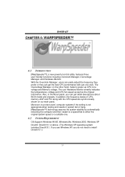
... click. The Overvoltage Manager, on our main panel. Also, in system fail or hang, [WarpSpeeder™] technology assures the system stability by automatically rebooting the computer and then restart to power up CPU core voltage and Memory voltage. The cool Hardware Monitor smartly indicates the temperatures, voltage and CPU fan speed as well as the chipset information. If you use Windows XP, you can get detail descriptions about BIOS model and chipsets.
... click. The Overvoltage Manager, on our main panel. Also, in system fail or hang, [WarpSpeeder™] technology assures the system stability by automatically rebooting the computer and then restart to power up CPU core voltage and Memory voltage. The cool Hardware Monitor smartly indicates the temperatures, voltage and CPU fan speed as well as the chipset information. If you use Windows XP, you can get detail descriptions about BIOS model and chipsets.


