
K8T890-A9 user's manual
Page 2
...1.2 Package List 4 1.3 Layout and Components 5 Chapter 2: Hardware Installation 6 2.1 Installing Central Processing Unit (CPU 6 2.2 FAN Headers 7 2.3 Installing System Memory 8 2.4 Connectors and Slots 9 Chapter 3: Headers & Jumpers Setup 12 3.1 How to Setup Jumpers 12 3.2 Detail Settings 12 Chapter 4: Useful Help 19 4.1 Award BIOS Beep Code 19 4.2 Extra Information 19 4.3 Troubleshooting 21 Chapter 5: WarpSpeeder 22 5.1 Introduction 22 5.2 System Requirement 22 5.3 Installation 23 5.4 [WarpSpeeder™] includes 1 tray icon and 5 panels 24...
...1.2 Package List 4 1.3 Layout and Components 5 Chapter 2: Hardware Installation 6 2.1 Installing Central Processing Unit (CPU 6 2.2 FAN Headers 7 2.3 Installing System Memory 8 2.4 Connectors and Slots 9 Chapter 3: Headers & Jumpers Setup 12 3.1 How to Setup Jumpers 12 3.2 Detail Settings 12 Chapter 4: Useful Help 19 4.1 Award BIOS Beep Code 19 4.2 Extra Information 19 4.3 Troubleshooting 21 Chapter 5: WarpSpeeder 22 5.1 Introduction 22 5.2 System Requirement 22 5.3 Installation 23 5.4 [WarpSpeeder™] includes 1 tray icon and 5 panels 24...
K8T890-A9 user's manual
Page 3
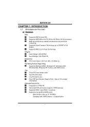
... CPU Supports AMD Socket 939. AMD 64 architecture enables simultaneous 32 and 64 bit computing. Two serial ATA connectors support 2 SATA devices. Compliant with SATA Version 1.0 specification. 1 Chipset North Bridge: VIA K8T890. Supports RAID 0 and RAID 1 functions. Supports HyperTransport Technology up to 2000MT/s Full duplex. K8T890-A9 CHAPTER 1: INTRODUCTION 1.1 MOTHERBOARD FEATURES A. Dimension ATX Form Factor: 29.31cm (W) x 24.38cm (L) Operating System Supporting Supports Windows 98SE, Windows NT, Windows 2000, Windows ME, Windows XP, Fedora, and UNIX series. One XGP slot...
... CPU Supports AMD Socket 939. AMD 64 architecture enables simultaneous 32 and 64 bit computing. Two serial ATA connectors support 2 SATA devices. Compliant with SATA Version 1.0 specification. 1 Chipset North Bridge: VIA K8T890. Supports RAID 0 and RAID 1 functions. Supports HyperTransport Technology up to 2000MT/s Full duplex. K8T890-A9 CHAPTER 1: INTRODUCTION 1.1 MOTHERBOARD FEATURES A. Dimension ATX Form Factor: 29.31cm (W) x 24.38cm (L) Operating System Supporting Supports Windows 98SE, Windows NT, Windows 2000, Windows ME, Windows XP, Fedora, and UNIX series. One XGP slot...

K8T890-A9 user's manual
Page 4
...'97 Version 2.3 specification. 2 Maximum memory size is up to 4GB. (Following table is only for reference.) DIMM Socket Location DDR Module Total Memory Size (MB) DIMM1 128MB/256MB/512MB/1GB *1 DIMM2 DIMM3 128MB/256MB/512MB/1GB *1 Max is 4 GB. 128MB/256MB/512MB/1GB *1 DIMM4 128MB/256MB/512MB/1GB *1 Super I/O Chip: ITE IT8705AF GX. Onboard IDE Two IDE connectors support 4 hard disk drives. K8T890-A9 System Memory Supports dual channel DDR up to 8 banks. RTL8100C (optional). Supports...
...'97 Version 2.3 specification. 2 Maximum memory size is up to 4GB. (Following table is only for reference.) DIMM Socket Location DDR Module Total Memory Size (MB) DIMM1 128MB/256MB/512MB/1GB *1 DIMM2 DIMM3 128MB/256MB/512MB/1GB *1 Max is 4 GB. 128MB/256MB/512MB/1GB *1 DIMM4 128MB/256MB/512MB/1GB *1 Super I/O Chip: ITE IT8705AF GX. Onboard IDE Two IDE connectors support 4 hard disk drives. K8T890-A9 System Memory Supports dual channel DDR up to 8 banks. RTL8100C (optional). Supports...
K8T890-A9 user's manual
Page 5
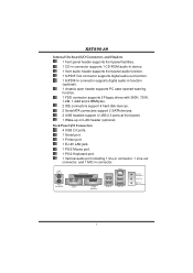
...-in connector. K8T890-A9 Internal On-board I /O Connectors 4 USB 2.0 ports. 1 Serial port. 1 Printer port. 1 RJ-45 LAN jack. 1 PS/2 Mouse port. 1 PS/2 Keyboard port. 1 Vertical audio port including 1 line-in connector, 1 Line out connector, and 1 MIC in function (optional). 1 chassis open header supports PC case-opened warning function. 1 FDD connector supports 2 Floppy drives with 360K, 720K, 1.2M, 1.44M and 2.88Mbytes. 2 IDE connectors support 4 hard disk devices. 2 Serial ATA connectors support 2 SATA devices. 2 USB headers support 4 USB 2.0 ports at front panel. 1 Wake-up on LAN header...
...-in connector. K8T890-A9 Internal On-board I /O Connectors 4 USB 2.0 ports. 1 Serial port. 1 Printer port. 1 RJ-45 LAN jack. 1 PS/2 Mouse port. 1 PS/2 Keyboard port. 1 Vertical audio port including 1 line-in connector, 1 Line out connector, and 1 MIC in function (optional). 1 chassis open header supports PC case-opened warning function. 1 FDD connector supports 2 Floppy drives with 360K, 720K, 1.2M, 1.44M and 2.88Mbytes. 2 IDE connectors support 4 hard disk devices. 2 Serial ATA connectors support 2 SATA devices. 2 USB headers support 4 USB 2.0 ports at front panel. 1 Wake-up on LAN header...

K8T890-A9 user's manual
Page 6
Supports APM1.2. K8T890-A9 B. Supports USB Function. BIOS & Software BIOS Award legal BIOS. Supports ACPI. Software Supports 9th TouchTM, FlasherTM, WinFlasherTM, and WarpspeederTM. 1.2 PACKAGE LIST FDD cable x1 HDD cable x1 User's Manual x1 Fully Setup Driver CD x1 Rear I/O panel for ATX case x1 USB 2.0 cable x1 (optional) Serial ATA cable x2 (optional) S/PDIF out cable x1 (optional) 4
Supports APM1.2. K8T890-A9 B. Supports USB Function. BIOS & Software BIOS Award legal BIOS. Supports ACPI. Software Supports 9th TouchTM, FlasherTM, WinFlasherTM, and WarpspeederTM. 1.2 PACKAGE LIST FDD cable x1 HDD cable x1 User's Manual x1 Fully Setup Driver CD x1 Rear I/O panel for ATX case x1 USB 2.0 cable x1 (optional) Serial ATA cable x2 (optional) S/PDIF out cable x1 (optional) 4
K8T890-A9 user's manual
Page 7
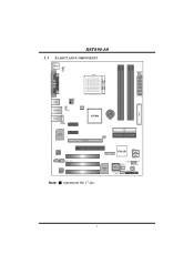
K8T890-A9 1.3 LAYOUT AND COMPONENTS JKBMS1 JKBV1 DIMM2 DIMM4 DIMM1 DIMM3 J1(optional) JCOM1 Socket 939 JPRNT1 JCOM2 (optional) JUSB3 JUSBLAN1 JATXPWR2 JUSBV1 JCFAN1 JAUDIO2 JAUDIO1 PCI-EX1_2 K8T890 BAT1 LAN (optional) PCI-EX1_1 PCI-EX16 JUSBV2 JATXPWR1 IDE1 IDE2 FDD1 LAN 10/100 JCDIN1 XGP1 PCI1 JSPDIF_OUT1 PCI2 Codec PCI3 JUSB1 JUSB2 VT8237R JSATA1 JSATA2 Super I/O BIOS JCMOS1 JCI1 JWOL1 (optional) JDJ1(optional) JSFAN1 JSPDIF_IN1 (optional) JPANEL1 Note: ■ represents the 1st pin. 5
K8T890-A9 1.3 LAYOUT AND COMPONENTS JKBMS1 JKBV1 DIMM2 DIMM4 DIMM1 DIMM3 J1(optional) JCOM1 Socket 939 JPRNT1 JCOM2 (optional) JUSB3 JUSBLAN1 JATXPWR2 JUSBV1 JCFAN1 JAUDIO2 JAUDIO1 PCI-EX1_2 K8T890 BAT1 LAN (optional) PCI-EX1_1 PCI-EX16 JUSBV2 JATXPWR1 IDE1 IDE2 FDD1 LAN 10/100 JCDIN1 XGP1 PCI1 JSPDIF_OUT1 PCI2 Codec PCI3 JUSB1 JUSB2 VT8237R JSATA1 JSATA2 Super I/O BIOS JCMOS1 JCI1 JWOL1 (optional) JDJ1(optional) JSFAN1 JSPDIF_IN1 (optional) JPANEL1 Note: ■ represents the 1st pin. 5

K8T890-A9 user's manual
Page 9
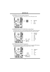
Connect the CPU FAN power cable to pin#1. The fan cable and connector may be connected to GND. 7 JCFAN1: CPU Fan Header JSFAN1: System Fan Header JCFAN1 1 3 JSFAN1 31 Pin Assignment 1 Ground 2 +12V 3 FAN RPM rate sense Note: The JCFAN1 and JSFAN1 support 3-pin head connector. B Step 5: Put the CPU Fan on the CPU and buckle it. Connect the fan cable to the connector while matching the black wire to the JCFAN1. K8T890-A9 Step 4: Hold the CPU down firmly, and then...
Connect the CPU FAN power cable to pin#1. The fan cable and connector may be connected to GND. 7 JCFAN1: CPU Fan Header JSFAN1: System Fan Header JCFAN1 1 3 JSFAN1 31 Pin Assignment 1 Ground 2 +12V 3 FAN RPM rate sense Note: The JCFAN1 and JSFAN1 support 3-pin head connector. B Step 5: Put the CPU Fan on the CPU and buckle it. Connect the fan cable to the connector while matching the black wire to the JCFAN1. K8T890-A9 Step 4: Hold the CPU down firmly, and then...
K8T890-A9 user's manual
Page 11
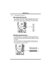
... two HDD connectors IDE1 (primary) and IDE2 (secondary). K8T890-A9 2.4 CONNECTORS AND SLOTS FDD1: Floppy Disk Connector The motherboard provides a standard floppy disk connector that provides PIO Mode 0~4, Bus Master, and Ultra DMA 66/ 100/ 133 functionality. This connector supports the provided floppy drive ribbon cables. 1 2 33 34 IDE1/IDE2: Hard Disk Connector The motherboard has a 32-bit Enhanced PCI IDE Controller that supports 360K, 720K, 1.2M, 1.44M and 2.88M floppy disk types. The IDE connectors can connect a master and a slave drive, so you can connect up...
... two HDD connectors IDE1 (primary) and IDE2 (secondary). K8T890-A9 2.4 CONNECTORS AND SLOTS FDD1: Floppy Disk Connector The motherboard provides a standard floppy disk connector that provides PIO Mode 0~4, Bus Master, and Ultra DMA 66/ 100/ 133 functionality. This connector supports the provided floppy drive ribbon cables. 1 2 33 34 IDE1/IDE2: Hard Disk Connector The motherboard has a 32-bit Enhanced PCI IDE Controller that supports 360K, 720K, 1.2M, 1.44M and 2.88M floppy disk types. The IDE connectors can connect a master and a slave drive, so you can connect up...
K8T890-A9 user's manual
Page 12
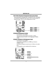
This PCI slot is equipped with 3 standard PCI slots. PCI-Express 1.0a compliant. - PCI-Express 1.0a compliant. - Data transfer bandwidth up to 250MB/s per direction, for expansion cards. PCI-Express supports a raw bit-rate of 4GB/s simultaneously per direction; 500MB/s in total. - K8T890-A9 PCI1~PCI3: Peripheral Component Interconnect Slots This motherboard is designated as 32 bits. PCI-EX1_1/PCI-Ex1_2: PCI-Express x1 slot - PCI stands for Peripheral Component Interconnect, and it is a bus standard...
This PCI slot is equipped with 3 standard PCI slots. PCI-Express 1.0a compliant. - PCI-Express 1.0a compliant. - Data transfer bandwidth up to 250MB/s per direction, for expansion cards. PCI-Express supports a raw bit-rate of 4GB/s simultaneously per direction; 500MB/s in total. - K8T890-A9 PCI1~PCI3: Peripheral Component Interconnect Slots This motherboard is designated as 32 bits. PCI-EX1_1/PCI-Ex1_2: PCI-Express x1 slot - PCI stands for Peripheral Component Interconnect, and it is a bus standard...
K8T890-A9 user's manual
Page 13
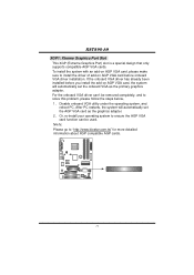
..., 1. Disable onboard VGA utility under the operating system, and reboot PC. After PC restarts, the system will automatically set the AGP VGA card as the primary graphics adapter. If the onboard VGA driver has already been installed before onboard VGA driver installation. Or, re-install your operating system to ensure the AGP VGA card function can 't be used. K8T890-A9 XGP1: Xtreme Graphics Port Slot This XGP (Extreme Graphics Port) slot is a special design that only supports compatible AGP VGA cards. To install...
..., 1. Disable onboard VGA utility under the operating system, and reboot PC. After PC restarts, the system will automatically set the AGP VGA card as the primary graphics adapter. If the onboard VGA driver has already been installed before onboard VGA driver installation. Or, re-install your operating system to ensure the AGP VGA card function can 't be used. K8T890-A9 XGP1: Xtreme Graphics Port Slot This XGP (Extreme Graphics Port) slot is a special design that only supports compatible AGP VGA cards. To install...

K8T890-A9 user's manual
Page 14
...: USB ports at JUSB3 and JUSBLAN1 are powered by +5V standby voltage. When the jumper cap is placed on Pin 2-3 individually. 12 JUSBV2: +5V for USB ports at front panel (JUSB1/JUSB2). JUSBV1 1 3 1 3 1 3 Pin 1-2 close JUSBV2 31 1 3 1 3 Pin 2-3 close ", if not, that means the jumper is "open". K8T890-A9 CHAPTER 3: HEADERS & JUMPERS SETUP 3.1 HOW TO SETUP JUMPERS The illustration shows how to support this function "Power-On system via USB device," "JUSBV1/ JUSBV2" jumper...
...: USB ports at JUSB3 and JUSBLAN1 are powered by +5V standby voltage. When the jumper cap is placed on Pin 2-3 individually. 12 JUSBV2: +5V for USB ports at front panel (JUSB1/JUSB2). JUSBV1 1 3 1 3 1 3 Pin 1-2 close JUSBV2 31 1 3 1 3 Pin 2-3 close ", if not, that means the jumper is "open". K8T890-A9 CHAPTER 3: HEADERS & JUMPERS SETUP 3.1 HOW TO SETUP JUMPERS The illustration shows how to support this function "Power-On system via USB device," "JUSBV1/ JUSBV2" jumper...

K8T890-A9 user's manual
Page 15
... 23 +5V 24 Ground 13 Note: In order to connect 24-pin power connector on Pin 2-3. K8T890-A9 JKBV1: Power Source Header for PS/2 Keyboard and Mouse 1 1 3 Pin 1-2 Close 3 +5V for PS/2 keyboard and mouse. 1 3 Pin 2-3 close PS/2 keyboard and mouse are powered by +5V standby voltage. JATXPWR1: ATX Power Source Connector This connector allows user to support this function "Power-on system via keyboard and mouse", "JKBV1" jumper cap should be placed on the ATX power supply.
... 23 +5V 24 Ground 13 Note: In order to connect 24-pin power connector on Pin 2-3. K8T890-A9 JKBV1: Power Source Header for PS/2 Keyboard and Mouse 1 1 3 Pin 1-2 Close 3 +5V for PS/2 keyboard and mouse. 1 3 Pin 2-3 close PS/2 keyboard and mouse are powered by +5V standby voltage. JATXPWR1: ATX Power Source Connector This connector allows user to support this function "Power-on system via keyboard and mouse", "JKBV1" jumper cap should be placed on the ATX power supply.
K8T890-A9 user's manual
Page 16
...: Serial ATA Connectors The motherboard has a PCI to connect additional USB cable on the PC front panel, and also can be connected with transfer rate of 1.5Gb/s. K8T890-A9 JATXPWR2: ATX Power Source Connector By connecting this connector, it will provide +12V to CPU power circuit. 4 3 Pin Assignment 1 2 1 +12V 2 +12V 3 Ground 4 Ground JUSB1/JUSB2: Headers for USB 2.0 Ports at Front Panel This header allows user to SATA Controller with 2 channels SATA interface, it satisfies the SATA 1.0 spec and with internal USB devices, like USB card reader...
...: Serial ATA Connectors The motherboard has a PCI to connect additional USB cable on the PC front panel, and also can be connected with transfer rate of 1.5Gb/s. K8T890-A9 JATXPWR2: ATX Power Source Connector By connecting this connector, it will provide +12V to CPU power circuit. 4 3 Pin Assignment 1 2 1 +12V 2 +12V 3 Ground 4 Ground JUSB1/JUSB2: Headers for USB 2.0 Ports at Front Panel This header allows user to SATA Controller with 2 channels SATA interface, it satisfies the SATA 1.0 spec and with internal USB devices, like USB card reader...
K8T890-A9 user's manual
Page 17
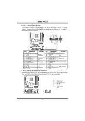
... Right Channel Input 15 PWR_LED SLP On/Off ++ 2 1 +- K8T890-A9 JPANEL1: Front Panel Header This 24-pin connector includes Power-on button IrDA Connector JCDIN1: CD-ROM Audio-in Connector This connector allows user to connect the PC case's front panel switch functions. SPK RST HLED IR 24 23 IR Pin Assignment 1 +5V 3 N/A 5 N/A 7 Speaker 9 HDD LED (+) 11 HDD LED (-) 13 Ground 15 Reset control 17 N/A 19 N/A 21 +5V 23 IRTX Function Pin Assignment 2 Sleep control Speaker Connector 4 Ground 6 N/A 8 Power LED (+) Hard drive LED 10 Power LED (+) 12 Power LED...
... Right Channel Input 15 PWR_LED SLP On/Off ++ 2 1 +- K8T890-A9 JPANEL1: Front Panel Header This 24-pin connector includes Power-on button IrDA Connector JCDIN1: CD-ROM Audio-in Connector This connector allows user to connect the PC case's front panel switch functions. SPK RST HLED IR 24 23 IR Pin Assignment 1 +5V 3 N/A 5 N/A 7 Speaker 9 HDD LED (+) 11 HDD LED (-) 13 Ground 15 Reset control 17 N/A 19 N/A 21 +5V 23 IRTX Function Pin Assignment 2 Sleep control Speaker Connector 4 Ground 6 N/A 8 Power LED (+) Hard drive LED 10 Power LED (+) 12 Power LED...

K8T890-A9 user's manual
Page 18
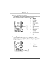
...: Chassis Open Header This connector allows system to connect the PCI bracket SPDIF output header. If the signal has been triggered, it will record to connect the PCI bracket SPDIF input header. Pin Assignment 1 +5V 2 SPDIF_OUT 3 Ground 3 1 JSPDIF_IN1 (optional): Digital Audio-in Connector This connector allows user to the CMOS and show the message on next boot-up. Pin Assignment 1 Case open status. K8T890-A9 JSPDIF_OUT1: Digital Audio-out Connector This connector allows user to monitor PC case open...
...: Chassis Open Header This connector allows system to connect the PCI bracket SPDIF output header. If the signal has been triggered, it will record to connect the PCI bracket SPDIF input header. Pin Assignment 1 +5V 2 SPDIF_OUT 3 Ground 3 1 JSPDIF_IN1 (optional): Digital Audio-in Connector This connector allows user to the CMOS and show the message on next boot-up. Pin Assignment 1 Case open status. K8T890-A9 JSPDIF_OUT1: Digital Audio-out Connector This connector allows user to monitor PC case open...
K8T890-A9 user's manual
Page 19
... speaker Left J WOL1 (optional): Wake on LAN function in BIOS is received from the network. K8T890-A9 JAUDIO1: Front Panel Audio Header This header allows user to Enabled and that your system has an ATX power supply with the PC front panel. This feature requires the Wake up on LAN Header The connector powers up signal 13 17 Pin Assignment 1 +5V_SB 2 Ground 3 Wake-up the system when a wakeup packet or signal is set to connect the front audio...
... speaker Left J WOL1 (optional): Wake on LAN function in BIOS is received from the network. K8T890-A9 JAUDIO1: Front Panel Audio Header This header allows user to Enabled and that your system has an ATX power supply with the PC front panel. This feature requires the Wake up on LAN Header The connector powers up signal 13 17 Pin Assignment 1 +5V_SB 2 Ground 3 Wake-up the system when a wakeup packet or signal is set to connect the front audio...
K8T890-A9 user's manual
Page 20
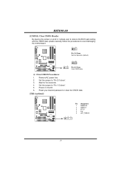
... user to restore the BIOS safe setting and the CMOS data, please carefully follow the procedures to "Pin 2-3 close ". 5. Set the jumper to avoid damaging the motherboard. 1 3 Pin 1-2 Close: Normal Operation (default). 1 3 13 Pin 2-3 Close: Clear CMOS data. ※ Clear CMOS Procedures: 1. Wait for five seconds. 4. JDJ1 (optional) 135 Pin Assignment 1 SMBDATA 2 SMBCLK 3 INT_B 4 Key 5 AXT_PWROK 18 K8T890-A9 JCMOS1: Clear CMOS Header By placing the jumper on the AC. 6. Remove AC power line. 2. Reset your desired password or clear...
... user to restore the BIOS safe setting and the CMOS data, please carefully follow the procedures to "Pin 2-3 close ". 5. Set the jumper to avoid damaging the motherboard. 1 3 Pin 1-2 Close: Normal Operation (default). 1 3 13 Pin 2-3 Close: Clear CMOS data. ※ Clear CMOS Procedures: 1. Wait for five seconds. 4. JDJ1 (optional) 135 Pin Assignment 1 SMBDATA 2 SMBCLK 3 INT_B 4 Key 5 AXT_PWROK 18 K8T890-A9 JCMOS1: Clear CMOS Header By placing the jumper on the AC. 6. Remove AC power line. 2. Reset your desired password or clear...
K8T890-A9 user's manual
Page 21
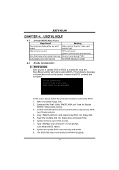
... bootable disk into floppy disk. 5. Confirm motherboard model and download the respectively BIOS from the Biostar website: www.biostar.com.tw 3. Copy "AWDFLASH.exe" and respectively BIOS into floppy drive and press Enter. 6. System will boot-up Long beeps every other second Meaning Video card not found or video card memory bad CPU overheated System will shut down automatically No error found during POST No DRAM detected or install 4.2 EXTRA INFORMATION A. Download the Flash Utility "AWDFLASH.exe" from Biostar website. 4. BIOS Update...
... bootable disk into floppy disk. 5. Confirm motherboard model and download the respectively BIOS from the Biostar website: www.biostar.com.tw 3. Copy "AWDFLASH.exe" and respectively BIOS into floppy drive and press Enter. 6. System will boot-up Long beeps every other second Meaning Video card not found or video card memory bad CPU overheated System will shut down automatically No error found during POST No DRAM detected or install 4.2 EXTRA INFORMATION A. Download the Flash Utility "AWDFLASH.exe" from Biostar website. 4. BIOS Update...
K8T890-A9 user's manual
Page 23
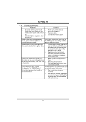
... the drive type in . Backing up data and applications files. Make sure correct information is extremely important. inside power supply does not turn on , power indicator lights are on . Set master/slave jumpers correctly. 2. Contact technical support. 2. Indicator light on keyboard does not turn 2. Keyboard lights are lit, and hard drive is impossible. Call the drive manufacturers for compatibility with other drives. 21 Run SETUP program and select correct drive types. No power to disk controller board. K8T890-A9 4.3 TROUBLESHOOTING Probable...
... the drive type in . Backing up data and applications files. Make sure correct information is extremely important. inside power supply does not turn on , power indicator lights are on . Set master/slave jumpers correctly. 2. Contact technical support. 2. Indicator light on keyboard does not turn 2. Keyboard lights are lit, and hard drive is impossible. Call the drive manufacturers for compatibility with other drives. 21 Run SETUP program and select correct drive types. No power to disk controller board. K8T890-A9 4.3 TROUBLESHOOTING Probable...
K8T890-A9 user's manual
Page 24
... DirectX 8.1. With the Overclock Manager, users can easily adjust the frequency they prefer or they can get the best CPU performance with the CPU speed are synchronically shown on the other hand, helps to power up CPU core voltage and Memory voltage. If you use Windows XP, you can get detail descriptions about BIOS model and chipsets. The cool Hardware Monitor smartly indicates the temperatures, voltage and CPU fan speed as well as the...
... DirectX 8.1. With the Overclock Manager, users can easily adjust the frequency they prefer or they can get the best CPU performance with the CPU speed are synchronically shown on the other hand, helps to power up CPU core voltage and Memory voltage. If you use Windows XP, you can get detail descriptions about BIOS model and chipsets. The cool Hardware Monitor smartly indicates the temperatures, voltage and CPU fan speed as well as the...


