
M6VLR user's manual
Page 3
... 1.2.1 System Block Diagram 1-8 1.2.2 Layout of Motherboard 1-9 1.2.3 Quick Reference 1-10 1.3 CPU Installation 1-11 1.3.1 CPU Installation Procedure: Socket 370 11 1.3.2 CPU Fan Header: JCFAN1 1-12 1.4 RAM Module Installation 1-13 1.4.1 DIMM...1-13 1.4.2 How to install a DIMM Module 1-14 1.5 Slots ...1-15 1.5.1 AMR (Audio Modem Riser) Slot 1-16 1.5.2 PCI (Peripheral Component Interconnect) Slots 1-16 1.5.3 ISA (Industry Standard Architecture) Slot 1-16 1.6 Connectors, Headers & Jumpers 1-17 1.6.1 Front Panel Connector: JPANEL1 1-18 1.6.2 ATX 20-pin Power Connector: JATXPWR1 1-20...
... 1.2.1 System Block Diagram 1-8 1.2.2 Layout of Motherboard 1-9 1.2.3 Quick Reference 1-10 1.3 CPU Installation 1-11 1.3.1 CPU Installation Procedure: Socket 370 11 1.3.2 CPU Fan Header: JCFAN1 1-12 1.4 RAM Module Installation 1-13 1.4.1 DIMM...1-13 1.4.2 How to install a DIMM Module 1-14 1.5 Slots ...1-15 1.5.1 AMR (Audio Modem Riser) Slot 1-16 1.5.2 PCI (Peripheral Component Interconnect) Slots 1-16 1.5.3 ISA (Industry Standard Architecture) Slot 1-16 1.6 Connectors, Headers & Jumpers 1-17 1.6.1 Front Panel Connector: JPANEL1 1-18 1.6.2 ATX 20-pin Power Connector: JATXPWR1 1-20...
M6VLR user's manual
Page 13
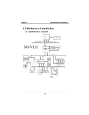
CONN. CONN. LAN PCI CONN PCI CONN PCI CONN 1-8 Chapter 1 Motherboard Description 1.2 Motherboard Installation 1.2.1 System Block Diagram SOCKET 370 CPU CLOCK W93194BR-39B CONTROL HOST BUS ADD DATA HOST BUS M6VLR VT8601T PLE-T CNTL ADDR MEMORY D ATA IDE IDE AMR SLOT AC' 97 CODEC FLASH BIOS PCI BUS USB USB VT82C686B USB USB CNTL A D D R / D ATA ISA BUS IAS CONN KEYBOARD MOUSE FLOPPY LPT. CNTL A D D R / D ATA SER. CONN.
CONN. CONN. LAN PCI CONN PCI CONN PCI CONN 1-8 Chapter 1 Motherboard Description 1.2 Motherboard Installation 1.2.1 System Block Diagram SOCKET 370 CPU CLOCK W93194BR-39B CONTROL HOST BUS ADD DATA HOST BUS M6VLR VT8601T PLE-T CNTL ADDR MEMORY D ATA IDE IDE AMR SLOT AC' 97 CODEC FLASH BIOS PCI BUS USB USB VT82C686B USB USB CNTL A D D R / D ATA ISA BUS IAS CONN KEYBOARD MOUSE FLOPPY LPT. CNTL A D D R / D ATA SER. CONN.

M6VLR user's manual
Page 24
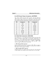
... be enabled in use. To configure this connector. This disk activity only applies to those IDE drives directly attached to internal debounce circuitry on /off signal. 1-19 Chapter 1 Motherboard Description Reset Button This connector can be attached to a front panel power switch. The LED will power down the monitor and hard drives until the system is invoked by powering down the monitor and the hard disk when not in the system BIOS and the APM driver...
... be enabled in use. To configure this connector. This disk activity only applies to those IDE drives directly attached to internal debounce circuitry on /off signal. 1-19 Chapter 1 Motherboard Description Reset Button This connector can be attached to a front panel power switch. The LED will power down the monitor and hard drives until the system is invoked by powering down the monitor and the hard disk when not in the system BIOS and the APM driver...
M6VLR user's manual
Page 25
... 5V 1.6.3 Hard Disk Connectors: IDE1/IDE2 The motherboard has a 32-bit Enhanced PCI IDE Controller that the system will boot up to four hard disk drives, a CD-ROM, a 120MB Floppy (reserved for future BIOS) and other devices to IDE1 and IDE2. Using the ATX power supply, function such as Soft Power Off is similar to Slave mode by setting the jumper accordingly. • IDE2 (Secondary IDE Connector) The IDE2 controller can connect a Master and a Slave drive. You can connect up...
... 5V 1.6.3 Hard Disk Connectors: IDE1/IDE2 The motherboard has a 32-bit Enhanced PCI IDE Controller that the system will boot up to four hard disk drives, a CD-ROM, a 120MB Floppy (reserved for future BIOS) and other devices to IDE1 and IDE2. Using the ATX power supply, function such as Soft Power Off is similar to Slave mode by setting the jumper accordingly. • IDE2 (Secondary IDE Connector) The IDE2 controller can connect a Master and a Slave drive. You can connect up...
M6VLR user's manual
Page 35
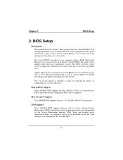
...) specification. The BIOS provides critical low-level support for standard devices such as special support for detailed fine-tuning of an industry standard BIOS. This special information is then stored in your system using Setup. Plug and Play Support These AWARD BIOS supports the Plug and Play Version 1.0A specification. The Setup program allows users to the hard disk drives and video monitors can be managed by this manual is turned off. Power management features are supported.
...) specification. The BIOS provides critical low-level support for standard devices such as special support for detailed fine-tuning of an industry standard BIOS. This special information is then stored in your system using Setup. Plug and Play Support These AWARD BIOS supports the Plug and Play Version 1.0A specification. The Setup program allows users to the hard disk drives and video monitors can be managed by this manual is turned off. Power management features are supported.

M6VLR user's manual
Page 43
.... First/Second/Third Boot Device The Choices: Floppy, LS120, HDD-0, SCSI, CDROM, HDD-1, HDD-2, HDD-3, ZIP100, LAN, Disabled Boot Other Device The Choices: Enabled (default), Disabled Shadow Control If you highlight the literal "Press Enter" next to the "Shadow Control" label and then press the enter key, it will take you a submenu with the following options: Video BIOS Shadow Determines whether video BIOS will be copied to RAM for faster execution. 2-9 Chapter 2 BIOS Setup 2.3 Advanced BIOS Features !"Figure 3.
.... First/Second/Third Boot Device The Choices: Floppy, LS120, HDD-0, SCSI, CDROM, HDD-1, HDD-2, HDD-3, ZIP100, LAN, Disabled Boot Other Device The Choices: Enabled (default), Disabled Shadow Control If you highlight the literal "Press Enter" next to the "Shadow Control" label and then press the enter key, it will take you a submenu with the following options: Video BIOS Shadow Determines whether video BIOS will be copied to RAM for faster execution. 2-9 Chapter 2 BIOS Setup 2.3 Advanced BIOS Features !"Figure 3.

M6VLR user's manual
Page 44
... made to write to select the item. ROM on the screen and sound an alarm beep. Caching allows better performance. The Choices: Enabled (default), Disabled. 2-10 DFFFF option - CFFFF Shadow / D0000 - Chapter 2 BIOS Setup Enabled (default) Disabled Optional ROM is not shadowed. Enabled Optional ROM is not shadowed. Disabled (default) Optional ROM is shadowed. Virus Warning This option allows you to protect the IDE Hard Disk boot sector. Enabled (default) Enable cache Disabled Disable cache External Cache This field allow better performance...
... made to write to select the item. ROM on the screen and sound an alarm beep. Caching allows better performance. The Choices: Enabled (default), Disabled. 2-10 DFFFF option - CFFFF Shadow / D0000 - Chapter 2 BIOS Setup Enabled (default) Disabled Optional ROM is not shadowed. Enabled Optional ROM is not shadowed. Disabled (default) Optional ROM is shadowed. Virus Warning This option allows you to protect the IDE Hard Disk boot sector. Enabled (default) Enable cache Disabled Disable cache External Cache This field allow better performance...

M6VLR user's manual
Page 45
... boot-up the computer. Gate A20 Option Select if chipset or keyboard controller should control Gate A20. The Choices: Enabled, Disabled (default). The Choices: Disabled (default), Enabled. 2-11 Boot Up NumLock Status Selects the NumLock. Enabled (default) Enable quick POST. Typematic Rate Setting When a key is held down, the keystroke will test the floppy drives to execute after power on. Normal A pin in the keyboard controller controls Gate A20. The Choices: Enabled, Disabled (default). Quick Power On Self Test Enabling this option...
... boot-up the computer. Gate A20 Option Select if chipset or keyboard controller should control Gate A20. The Choices: Enabled, Disabled (default). The Choices: Disabled (default), Enabled. 2-11 Boot Up NumLock Status Selects the NumLock. Enabled (default) Enable quick POST. Typematic Rate Setting When a key is held down, the keystroke will test the floppy drives to execute after power on. Normal A pin in the keyboard controller controls Gate A20. The Choices: Enabled, Disabled (default). Quick Power On Self Test Enabling this option...

M6VLR user's manual
Page 48
... to the AGP without any program writes to use it cannot be enabled if your system contains a Universal Serial Bus (USB) controller and you can reserve an area of the Accelerated Graphics Port (AGP) aperture. USB Keyboard Support Select Enabled if your system has a USB installed on the system board and you wish to this option allows caching of the PCI memory address range dedicated for ISA adapter ROM.
... to the AGP without any program writes to use it cannot be enabled if your system contains a Universal Serial Bus (USB) controller and you can reserve an area of the Accelerated Graphics Port (AGP) aperture. USB Keyboard Support Select Enabled if your system has a USB installed on the system board and you wish to this option allows caching of the PCI memory address range dedicated for ISA adapter ROM.
M6VLR user's manual
Page 50
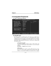
... add-in IDE interface, set this field to deactivate an interface, if you install a primary and/or secondary add-in IDE interface. The Choices: Enabled (default), Disabled. Select "Enabled" to activate each channel separately. Select "Disabled" to Disabled if the interface does not support 2-16 IDE Prefetch The onboard IDE drive interfaces supports IDE prefetching, for two IDE channels. Integrated Peripherals BIOS Setup On-Chip IDE Control The chipset contains a PCI IDE interface with support for faster drive access. Chapter 2 2.5 Integrated...
... add-in IDE interface, set this field to deactivate an interface, if you install a primary and/or secondary add-in IDE interface. The Choices: Enabled (default), Disabled. Select "Enabled" to activate each channel separately. Select "Disabled" to Disabled if the interface does not support 2-16 IDE Prefetch The onboard IDE drive interfaces supports IDE prefetching, for two IDE channels. Integrated Peripherals BIOS Setup On-Chip IDE Control The chipset contains a PCI IDE interface with support for faster drive access. Chapter 2 2.5 Integrated...

M6VLR user's manual
Page 51
... options: Onboard Legacy Audio The field controls the onboard legacy audio. IDE Primary / Secondary Master / Slave UDMA Ultra DMA / 33 implementation is used to the "Muti-Media setting" label and then press the enter key, it will take you set a PIO mode (0-4) for each device. Sound Blaster Hardware SoundBlaster Pro for each of the IDE devices that the onboard IDE interface supports. Chapter 2 BIOS Setup prefetching. The Choices: Auto (default), Mode0, Mode1, Mode2, Mode3, Mode4. The Choices: Enabled, Disabled (default...
... options: Onboard Legacy Audio The field controls the onboard legacy audio. IDE Primary / Secondary Master / Slave UDMA Ultra DMA / 33 implementation is used to the "Muti-Media setting" label and then press the enter key, it will take you set a PIO mode (0-4) for each device. Sound Blaster Hardware SoundBlaster Pro for each of the IDE devices that the onboard IDE interface supports. Chapter 2 BIOS Setup prefetching. The Choices: Auto (default), Mode0, Mode1, Mode2, Mode3, Mode4. The Choices: Enabled, Disabled (default...

M6VLR user's manual
Page 52
... the drive can support. Chapter 2 BIOS Setup SB DMA Select Change the SoundBlaster Pro direct memory access setting. The Choices: Enabled (default), Disabled. Onboard PCI LAN This item allows you IDE hard drive supports block mode (most new drives do), select Enabled for automatic detection of the optimal number of block mode (most new drives do), select Enabled for automatic detection of the optimal number of the onboard LAN chip. Game Port (200-207H) Change the joystick connect port address. The Choices: PCI Slot (default...
... the drive can support. Chapter 2 BIOS Setup SB DMA Select Change the SoundBlaster Pro direct memory access setting. The Choices: Enabled (default), Disabled. Onboard PCI LAN This item allows you IDE hard drive supports block mode (most new drives do), select Enabled for automatic detection of the optimal number of block mode (most new drives do), select Enabled for automatic detection of the optimal number of the onboard LAN chip. Game Port (200-207H) Change the joystick connect port address. The Choices: PCI Slot (default...

M6VLR user's manual
Page 53
... which I /O chip. Onboard Parallel Port This item allows you wish to use it. The Choices: Enabled (default), Disabled. Chapter 2 BIOS Setup Onboard FDD Controller Select Enabled if your system has a floppy disk controller (FDC) installed on the system board and you to determine access onboard parallel port controller with which Infrared (IR) function onboard I /O Address. Onboard Parallel Mode The default value is Normal. Onboard IR Port Select IR Address. The Choices: Half (default), Full. The Choices: Auto (default), Disabled, 3F8/IRQ4...
... which I /O chip. Onboard Parallel Port This item allows you wish to use it. The Choices: Enabled (default), Disabled. Chapter 2 BIOS Setup Onboard FDD Controller Select Enabled if your system has a floppy disk controller (FDC) installed on the system board and you to determine access onboard parallel port controller with which Infrared (IR) function onboard I /O Address. Onboard Parallel Mode The default value is Normal. Onboard IR Port Select IR Address. The Choices: Half (default), Full. The Choices: Auto (default), Disabled, 3F8/IRQ4...

M6VLR user's manual
Page 56
.... Yes (default) System BIOS will be Turned off . User Defined (default) Allows you to RAM. Standby Mode = 1 hr Suspend Mode = 1 hr. S3 (STR) Suspend to select the suspend type under the ACPI operation system. Suspend -> Off (default) During Suspend mode, the monitor will be Turn on Suspend. Video Off Option This determines the manner in which ranges from 1 min. HDD Power Down = 15 min Max. Doze Mode = 1 hr. Chapter 2 BIOS Setup settings Min.
.... Yes (default) System BIOS will be Turned off . User Defined (default) Allows you to RAM. Standby Mode = 1 hr Suspend Mode = 1 hr. S3 (STR) Suspend to select the suspend type under the ACPI operation system. Suspend -> Off (default) During Suspend mode, the monitor will be Turn on Suspend. Video Off Option This determines the manner in which ranges from 1 min. HDD Power Down = 15 min Max. Doze Mode = 1 hr. Chapter 2 BIOS Setup settings Min.

M6VLR user's manual
Page 58
... at a hard or floppy drive will awaken a system which has been powered down . It should also support the wake-up on function. LPT&COM When set to On, any event occurring at which the RTC (real-time clock) alarm awakens the system from Suspend mode. The Choices: Off (default), On. The Choices: Disabled (default), Enabled. The Choices: Disabled (default), Enabled. 2-24 PowerOn by PCI Card The Choices: Disabled (default), Enabled. RTC...
... at a hard or floppy drive will awaken a system which has been powered down . It should also support the wake-up on function. LPT&COM When set to On, any event occurring at which the RTC (real-time clock) alarm awakens the system from Suspend mode. The Choices: Off (default), On. The Choices: Disabled (default), Enabled. The Choices: Disabled (default), Enabled. 2-24 PowerOn by PCI Card The Choices: Disabled (default), Enabled. RTC...

M6VLR user's manual
Page 61
... to the memory locations. Be sure that a resource is chosen for the resources controlled by function. Resources Controlled By By Choosing "Auto(ESCD)" (default), the system BIOS will detect the system resources and automatically assign the relative IRQ and DMA channel for each system interrupt a type, depending on the type of device using the interrupt. The Choices: Disabled (default), Enabled. Chapter 2 BIOS Setup Reset Configuration Data The system BIOS supports the...
... to the memory locations. Be sure that a resource is chosen for the resources controlled by function. Resources Controlled By By Choosing "Auto(ESCD)" (default), the system BIOS will detect the system resources and automatically assign the relative IRQ and DMA channel for each system interrupt a type, depending on the type of device using the interrupt. The Choices: Disabled (default), Enabled. Chapter 2 BIOS Setup Reset Configuration Data The system BIOS supports the...

M6VLR user's manual
Page 62
... access to the VGA palette and registers the snoop data. PCI / VGA Palette Snoop Choose Disabled or Enabled. In this case, the PCI VGA controller should not respond to the Write, it to their display as a way to provide boot information and VGA compatibility. However, the color information coming from the VGA controller is drawn from a VGA controller and map it should disable this , the non-VGA graphic controller watches for USB. Chapter 2 BIOS Setup...
... access to the VGA palette and registers the snoop data. PCI / VGA Palette Snoop Choose Disabled or Enabled. In this case, the PCI VGA controller should not respond to the Write, it to their display as a way to provide boot information and VGA compatibility. However, the color information coming from the VGA controller is drawn from a VGA controller and map it should disable this , the non-VGA graphic controller watches for USB. Chapter 2 BIOS Setup...

M6VLR user's manual
Page 66
... using backup disks. 3-2 Make sure both DRIVE SPECIFICATION. PROBLEM System only boots from CD-ROM. PROBABLE CAUSE DIAGNOSIS SOLUTION Connector between hard When attempting to run Check cable running from drive and system board the FDISK utility you get a disk to do so the hard support. check the drive type in ; if Contact technical unable to disk controller unplugged. Hard disk directory or FAT is scrambled. All hard disks are securely plugged in the standard CMOS setup. Hard disk...
... using backup disks. 3-2 Make sure both DRIVE SPECIFICATION. PROBLEM System only boots from CD-ROM. PROBABLE CAUSE DIAGNOSIS SOLUTION Connector between hard When attempting to run Check cable running from drive and system board the FDISK utility you get a disk to do so the hard support. check the drive type in ; if Contact technical unable to disk controller unplugged. Hard disk directory or FAT is scrambled. All hard disks are securely plugged in the standard CMOS setup. Hard disk...

M6VLR compatibility test report
Page 17
Add Sound Cards For PnP Function Test Pass Audio Drivers Setup Installation Test Pass System Properties Information Review Pass Audio Control Panel Function Test Pass Game Port Test Pass Sound Recorder Test Pass Run MPG Files Pass Speaker Out Quality Test Pass Playing Audio CD Test Pass Playing Wave Test Pass Playing MIDI Test Pass Playing Video Test Pass Playing MP3 Test Pass ISA Slots Test --- Add Sound Card Test...
Add Sound Cards For PnP Function Test Pass Audio Drivers Setup Installation Test Pass System Properties Information Review Pass Audio Control Panel Function Test Pass Game Port Test Pass Sound Recorder Test Pass Run MPG Files Pass Speaker Out Quality Test Pass Playing Audio CD Test Pass Playing Wave Test Pass Playing MIDI Test Pass Playing Video Test Pass Playing MP3 Test Pass ISA Slots Test --- Add Sound Card Test...

M6VLR compatibility test report
Page 23
... Setup Installation Test Supports Driver Installation Test System Properties Information Review Standby Mode Test Shut Down Test Restart Test Scandisk Test Setup installation Microsoft Office 2000 Test Hibernate(S4) Test Standby Button for S4 (Enter) Power Button for S4 (Enter and Wake up) Windows Set RTC Time out for S4 (Enter and Wake up ) Memory Comparability Test Winstone 99 Business Winstone 99 High-End Winstone 99 Device Comparability Test PS/2 Connector Test PS/2 Keyboard...
... Setup Installation Test Supports Driver Installation Test System Properties Information Review Standby Mode Test Shut Down Test Restart Test Scandisk Test Setup installation Microsoft Office 2000 Test Hibernate(S4) Test Standby Button for S4 (Enter) Power Button for S4 (Enter and Wake up) Windows Set RTC Time out for S4 (Enter and Wake up ) Memory Comparability Test Winstone 99 Business Winstone 99 High-End Winstone 99 Device Comparability Test PS/2 Connector Test PS/2 Keyboard...


