

M7MKE user's manual
Page 12
... Slot (AGP1) M. Wake-On-LAN Connector (WOL) C. CMOS Function Selection (JBAT) Selection (J1) P. CD Audio-In Connector (J4) Q. PCI BUS Slots (PCI1-5) T. ATX Power Connector (CN1) J. CPU Fan Connector (FAN1) K. FDD Connector (FDD1) E. Secondary IDE Connector (IDE2) F. Telephony Connector (J5) R. Slot A (CPU1) AMR BUS Slot (AMR1) N. Wake-On MODEM Connector (WOM) D. AMR CODEC Primary/Secondary O. ISA BUS Slot (ISA1) U. CPU Clock Selection (SW1) H. Chapter 1 Motherboard Description 1.3 Motherboard Connectors A A. Back Panel I . System Fan Connector...
... Slot (AGP1) M. Wake-On-LAN Connector (WOL) C. CMOS Function Selection (JBAT) Selection (J1) P. CD Audio-In Connector (J4) Q. PCI BUS Slots (PCI1-5) T. ATX Power Connector (CN1) J. CPU Fan Connector (FAN1) K. FDD Connector (FDD1) E. Secondary IDE Connector (IDE2) F. Telephony Connector (J5) R. Slot A (CPU1) AMR BUS Slot (AMR1) N. Wake-On MODEM Connector (WOM) D. AMR CODEC Primary/Secondary O. ISA BUS Slot (ISA1) U. CPU Clock Selection (SW1) H. Chapter 1 Motherboard Description 1.3 Motherboard Connectors A A. Back Panel I . System Fan Connector...

M7MKE user's manual
Page 13
... 2 No Connection (Speaker 15 Ground 3 No Connection Connector) 16 Ground 4 +5V 17 Green Control 5 Power LED(+) PW-LED 18 Ground 6 No Connection (Power LED) 19 No Connection 7 Ground 20 HDD LED(-) 8 No Connection NC 21 HDD LED(+) 9 No Connection 22 +5V 10 Power Switch PW-BN (ATX 23 No Connection 11 Standby Voltage Power Button) 24 IRRX 12 Reset Control RST (Reset 25 Ground 13 Ground Button) 26 IRTX Function V (VCC) G (Ground) Sleep NC NC HD-LED (HDD LED) IR (IrDA Connector) LED NC IR...
... 2 No Connection (Speaker 15 Ground 3 No Connection Connector) 16 Ground 4 +5V 17 Green Control 5 Power LED(+) PW-LED 18 Ground 6 No Connection (Power LED) 19 No Connection 7 Ground 20 HDD LED(-) 8 No Connection NC 21 HDD LED(+) 9 No Connection 22 +5V 10 Power Switch PW-BN (ATX 23 No Connection 11 Standby Voltage Power Button) 24 IRRX 12 Reset Control RST (Reset 25 Ground 13 Ground Button) 26 IRTX Function V (VCC) G (Ground) Sleep NC NC HD-LED (HDD LED) IR (IrDA Connector) LED NC IR...

M7MKE user's manual
Page 29
Chapter 1 Motherboard Description 1.7.2 System Fan Connector : FAN2 Pin No. 1 2 3 Assignment Control PIN +12V GND 1.7.3 Wake-On MODEM Header : WOM (Optional) Pin No. 1 2 3 Assignment 5V SB GND Wake Up 1.7.4 Wake-On-LAN Header : WOL Pin No. 1 2 3 Assignment 5V SB Ground Wake up 1.7.5 AMR Code Primary/Secondary Selection : J1 Pin No. 1-2 2-3 Assignment Secondary Primary
Chapter 1 Motherboard Description 1.7.2 System Fan Connector : FAN2 Pin No. 1 2 3 Assignment Control PIN +12V GND 1.7.3 Wake-On MODEM Header : WOM (Optional) Pin No. 1 2 3 Assignment 5V SB GND Wake Up 1.7.4 Wake-On-LAN Header : WOL Pin No. 1 2 3 Assignment 5V SB Ground Wake up 1.7.5 AMR Code Primary/Secondary Selection : J1 Pin No. 1-2 2-3 Assignment Secondary Primary
M7MKE user's manual
Page 38
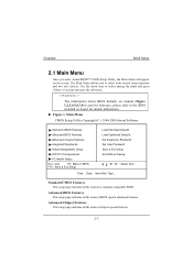
WARNING !! ! Standard CMOS Features Advanced BIOS Features Advanced Chipset Features Integrated Peripherals Power Management Setup PnP/PCI Configurations PC Health Status Esc : Quit F9 : Menu in BIOS F10 : Save & Exit Setup Load Fail-Safe Defaults Load Optimized Defaults Set Supervisor Password Set User Password Save & Exit Setup Exit Without Saving : Select Item Time, Date, Hard Disk Type... Chapter2 2.1 Main Menu BIOS Setup !!
WARNING !! ! Standard CMOS Features Advanced BIOS Features Advanced Chipset Features Integrated Peripherals Power Management Setup PnP/PCI Configurations PC Health Status Esc : Quit F9 : Menu in BIOS F10 : Save & Exit Setup Load Fail-Safe Defaults Load Optimized Defaults Set Supervisor Password Set User Password Save & Exit Setup Exit Without Saving : Select Item Time, Date, Hard Disk Type... Chapter2 2.1 Main Menu BIOS Setup !!
M7MKE user's manual
Page 41
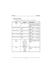
... in Video EGA/VGA CGA 40 Select the default video device. sub menu of floppy disk drive installed in your system. 720K, 3.5 in 1.44M, 3.5 in 2.88M, 3.5 in Select the type of detailed options. IDE Primary Master Options are in its sub Press to enter the menu. sub menu of detailed options IDE Primary Slave Options are in its sub Press to enter the menu. Note that the 'Day' automatically changes when you set the...
... in Video EGA/VGA CGA 40 Select the default video device. sub menu of floppy disk drive installed in your system. 720K, 3.5 in 1.44M, 3.5 in 2.88M, 3.5 in Select the type of detailed options. IDE Primary Master Options are in its sub Press to enter the menu. sub menu of detailed options IDE Primary Slave Options are in its sub Press to enter the menu. Note that the 'Day' automatically changes when you set the...
M7MKE user's manual
Page 43
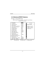
... Test First Boot Device Second Boot Device Third Boot Device Boot Other Device Swap Floppy Drive Boot Up Floppy Seek Boot Up NumLock Status Gate A20 Option Typematic Rate Setting X Typematic Rate (Chars / Sec) X Typematic Delay (Msec) Security Option OS Select For DRAM > 64MB Video BIOS Shadow Enabled Disabled Enabled Enabled Enabled Enabled Floppy HDD-0 LS/ZIP Enabled Disabled Enabled On Fast Disabled 6 250 Enabled Non-OS2 Enabled Item Help Menu Level Allows you to choose Whether to display Fulllogo or text mode When booting : Move Enter :Select...
... Test First Boot Device Second Boot Device Third Boot Device Boot Other Device Swap Floppy Drive Boot Up Floppy Seek Boot Up NumLock Status Gate A20 Option Typematic Rate Setting X Typematic Rate (Chars / Sec) X Typematic Delay (Msec) Security Option OS Select For DRAM > 64MB Video BIOS Shadow Enabled Disabled Enabled Enabled Enabled Enabled Floppy HDD-0 LS/ZIP Enabled Disabled Enabled On Fast Disabled 6 250 Enabled Non-OS2 Enabled Item Help Menu Level Allows you to choose Whether to display Fulllogo or text mode When booting : Move Enter :Select...
M7MKE user's manual
Page 47
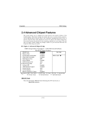
Chapter2 BIOS Setup 2.4 Advanced Chipset Features ! DRAM Clock Memory Hole Host CLK Disabled Item Help System BIOS Cachesable Video RAM Cacheable AGP Aperture Size AGP-4X Mode AGP Driving Control X AGP Driving Value OnChip USB USB Keyboard Support OnChip Sound OnChip Modem Memory Parity/ECC Check Disabled Disabled 64M Enabled Auto DA Enabled Disabled Auto Auto Disabled Menu Level : Move Enter :Select +/-/PU/PD :Value F10 :Save ESC :Exit F1 :General Help F5 :Previous Values F6 :Fail-Safe Defaults F7 : Optimized Defaults
Chapter2 BIOS Setup 2.4 Advanced Chipset Features ! DRAM Clock Memory Hole Host CLK Disabled Item Help System BIOS Cachesable Video RAM Cacheable AGP Aperture Size AGP-4X Mode AGP Driving Control X AGP Driving Value OnChip USB USB Keyboard Support OnChip Sound OnChip Modem Memory Parity/ECC Check Disabled Disabled 64M Enabled Auto DA Enabled Disabled Auto Auto Disabled Menu Level : Move Enter :Select +/-/PU/PD :Value F10 :Save ESC :Exit F1 :General Help F5 :Previous Values F6 :Fail-Safe Defaults F7 : Optimized Defaults

M7MKE user's manual
Page 50
... UDMA Init Display First IDE HDD Block Mode Onboard FDD Controller Onboard Serial Port 1 Onboard Serial Port 2 UART 2 Mode X IR Function Duplex X TX, RX inverting enable Onboard Parallel Port Onboard Parallel Mode X ECP Mode Use DMA Parallel Port EPP Type Onboard Legacy Audio Sound Blaster SB I/O Base Address SB IRQ Select SB DMA Select MPU-401 MPU-401 I/O Address Game Port (200-207H) Enabled Enabled Enabled Auto Auto Auto Auto Auto Auto Auto Auto PCI Slot Enabled Enabled 3F8/IRQ4 2F8/IRQ3 Standard Half No, Yes 378/IRQ7 EPP 3 EPP1.9 Enabled Disabled 220H IRQ...
... UDMA Init Display First IDE HDD Block Mode Onboard FDD Controller Onboard Serial Port 1 Onboard Serial Port 2 UART 2 Mode X IR Function Duplex X TX, RX inverting enable Onboard Parallel Port Onboard Parallel Mode X ECP Mode Use DMA Parallel Port EPP Type Onboard Legacy Audio Sound Blaster SB I/O Base Address SB IRQ Select SB DMA Select MPU-401 MPU-401 I/O Address Game Port (200-207H) Enabled Enabled Enabled Auto Auto Auto Auto Auto Auto Auto Auto PCI Slot Enabled Enabled 3F8/IRQ4 2F8/IRQ3 Standard Half No, Yes 378/IRQ7 EPP 3 EPP1.9 Enabled Disabled 220H IRQ...

M7MKE user's manual
Page 54
... Help Power Management User Define Menu Level PM Control by APM Yes Video Off Option Suspend -> Off Video Off Method V/H SYNC+Blank Modem Use IRQ 3 Soft-Off by PWR-BTTN Instant-Off HDD Power Down Disabled Suspend Mode Disabled VGA OFF LPT & COM LPT/COM HDD & FDD ON PCI Master OFF Wake Up On LAN/Ring Disabled RTC Alarm Resume Disabled X Date (of Month) 0 X Resume Time (hh:mm:ss) 0 0 0 : Move Enter...
... Help Power Management User Define Menu Level PM Control by APM Yes Video Off Option Suspend -> Off Video Off Method V/H SYNC+Blank Modem Use IRQ 3 Soft-Off by PWR-BTTN Instant-Off HDD Power Down Disabled Suspend Mode Disabled VGA OFF LPT & COM LPT/COM HDD & FDD ON PCI Master OFF Wake Up On LAN/Ring Disabled RTC Alarm Resume Disabled X Date (of Month) 0 X Resume Time (hh:mm:ss) 0 0 0 : Move Enter...

M7MKE user's manual
Page 58
Select No if you are using a Plug and Play capable operating system. Chapter2 2.7 PnP/PCI Configurations BIOS Setup ! PNP OS Installed Reset Configuration Data Resources Controlled By X IRQ Resources X DMA Resources PCI/VGA Palette Snoop Assign IRQ For VGA Assign IRQ For USB No Disabled Auto (ESCD) Press Enter Press Enter Disabled Enabled Enabled Item Help Menu Level Select Yes if you need the BIOS to configure non-boot devices : Move Enter :Select +/-/PU/PD :Value F10 :Save ESC :Exit F1 :General Help F5 :Previous Values F6 :Fail-Safe Defaults F7 : Optimized Defaults
Select No if you are using a Plug and Play capable operating system. Chapter2 2.7 PnP/PCI Configurations BIOS Setup ! PNP OS Installed Reset Configuration Data Resources Controlled By X IRQ Resources X DMA Resources PCI/VGA Palette Snoop Assign IRQ For VGA Assign IRQ For USB No Disabled Auto (ESCD) Press Enter Press Enter Disabled Enabled Enabled Item Help Menu Level Select Yes if you need the BIOS to configure non-boot devices : Move Enter :Select +/-/PU/PD :Value F10 :Save ESC :Exit F1 :General Help F5 :Previous Values F6 :Fail-Safe Defaults F7 : Optimized Defaults
M7MKE user's manual
Page 63
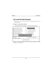
Chapter2 2.9 Load Fail-Safe Defaults BIOS Setup ! N PC Health Status Esc : Quit F10 : Save & Exit Setup : Select Item Load Fail-Safe Defaults Standard CMOS Features Load Fail-Safe Defaults Advanced BIOS Features Load Optimized Defaults Advanced Chipset Features Set Supervisor Password Integrated Peripherals Set User Password Power Management Setup Save & Exit Setup PnP/PCI Configurations Exit Without Saving Load Fail-Safe Defaults (Y / N)?
Chapter2 2.9 Load Fail-Safe Defaults BIOS Setup ! N PC Health Status Esc : Quit F10 : Save & Exit Setup : Select Item Load Fail-Safe Defaults Standard CMOS Features Load Fail-Safe Defaults Advanced BIOS Features Load Optimized Defaults Advanced Chipset Features Set Supervisor Password Integrated Peripherals Set User Password Power Management Setup Save & Exit Setup PnP/PCI Configurations Exit Without Saving Load Fail-Safe Defaults (Y / N)?

M7MKE user's manual
Page 64
N PC Health Status Esc : Quit F10 : Save & Exit Setup : Select Item Load Optimized Defaults Standard CMOS Features Load Fail-Safe Defaults Advanced BIOS Features Load Optimized Defaults Advanced Chipset Features Set Supervisor Password Integrated Peripherals Set User Password Power Management Setup Save & Exit Setup PnP/PCI Configurations Exit Without Saving Load Optimized Defaults (Y / N)? Chapter2 2.10 Load Optimized Defaults BIOS Setup !
N PC Health Status Esc : Quit F10 : Save & Exit Setup : Select Item Load Optimized Defaults Standard CMOS Features Load Fail-Safe Defaults Advanced BIOS Features Load Optimized Defaults Advanced Chipset Features Set Supervisor Password Integrated Peripherals Set User Password Power Management Setup Save & Exit Setup PnP/PCI Configurations Exit Without Saving Load Optimized Defaults (Y / N)? Chapter2 2.10 Load Optimized Defaults BIOS Setup !

M7MKE user's manual
Page 65
Standard CMOS Features Advanced BIOS Features Advanced Chipset Features Integrated Peripherals Power Management Setup PnP/PCI Configurations Enter Password: PC Health Status Esc : Quit F10 : Save & Exit Setup Load Fail-Safe Defaults Load Optimized Defaults Set Supervisor Password Set User Password Save & Exit Setup Exit Without Saving : Select Item Change/Set/Disable password Chapter2 BIOS Setup 2.11 Set Supervisor / User Password !
Standard CMOS Features Advanced BIOS Features Advanced Chipset Features Integrated Peripherals Power Management Setup PnP/PCI Configurations Enter Password: PC Health Status Esc : Quit F10 : Save & Exit Setup Load Fail-Safe Defaults Load Optimized Defaults Set Supervisor Password Set User Password Save & Exit Setup Exit Without Saving : Select Item Change/Set/Disable password Chapter2 BIOS Setup 2.11 Set Supervisor / User Password !
M7MKE user's manual
Page 67
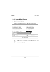
Chapter2 2.12 Save & Exit Setup ! Y PC Health Status Esc : Quit F10 : Save & Exit Setup : Select Item Save Data to CMOS and EXIT (Y/N)? BIOS Setup Standard CMOS Features Load Fail-Safe Defaults Advanced BIOS Features Load Optimized Defaults Advanced Chipset Features Set Supervisor Password Integrated Peripherals Set User Password Power Management Setup Save & Exit Setup PnP/PCI Configurations Exit Without Saving SAVE to CMOS
Chapter2 2.12 Save & Exit Setup ! Y PC Health Status Esc : Quit F10 : Save & Exit Setup : Select Item Save Data to CMOS and EXIT (Y/N)? BIOS Setup Standard CMOS Features Load Fail-Safe Defaults Advanced BIOS Features Load Optimized Defaults Advanced Chipset Features Set Supervisor Password Integrated Peripherals Set User Password Power Management Setup Save & Exit Setup PnP/PCI Configurations Exit Without Saving SAVE to CMOS
M7MKE user's manual
Page 69
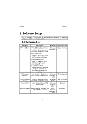
... to support AGP interface VGA Card. 3. Software Setup Software 3.1 Software List Category Description Platform Location in CD VIA 4-in-1 Drive * 1. IRQ Routing Driver Used for Windows Windows 95/98/NT/ 2000 \DirectX VIA AC97 Audio* Install the driver to support 95/98/NT4.0 Ultra DMA mode Hard Drive. 2. VIA IDE Bus Master Driver Windows \Mb_drv\Service Install the drivers to enable the DOS, VIA AC97 Audio Device Windows 95/98/NT4.0 / 2000 \Audio\VIA 3- Chapter 3 3. VIA Hardware VIA Hardware Monitor is a Windows \Mb_drv\Sysdiag Monitor * self...
... to support AGP interface VGA Card. 3. Software Setup Software 3.1 Software List Category Description Platform Location in CD VIA 4-in-1 Drive * 1. IRQ Routing Driver Used for Windows Windows 95/98/NT/ 2000 \DirectX VIA AC97 Audio* Install the driver to support 95/98/NT4.0 Ultra DMA mode Hard Drive. 2. VIA IDE Bus Master Driver Windows \Mb_drv\Service Install the drivers to enable the DOS, VIA AC97 Audio Device Windows 95/98/NT4.0 / 2000 \Audio\VIA 3- Chapter 3 3. VIA Hardware VIA Hardware Monitor is a Windows \Mb_drv\Sysdiag Monitor * self...
M7MKE user's manual
Page 70
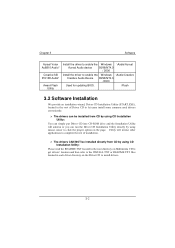
Chapter 3 Software Aureal Votex Au8810 Audio* Creative SB PCI128 Audio* Award Flash Utility Install the driver to cnable the Windows \Audio\Aureal Aureal Audio device 95/98/NT4.0 / 2000 Install the driver to enable the Windows \Audio\Creative Creative Audio Device 95/98/NT4.0 /2000 Used for updating BIOS. \Flash 3.2 Software Installation " The drivers can be installed from CD by using CD Installation Utility: " The drivers CAN NOT be installed directly from CD by using CD Installation Utility: 3-
Chapter 3 Software Aureal Votex Au8810 Audio* Creative SB PCI128 Audio* Award Flash Utility Install the driver to cnable the Windows \Audio\Aureal Aureal Audio device 95/98/NT4.0 / 2000 Install the driver to enable the Windows \Audio\Creative Creative Audio Device 95/98/NT4.0 /2000 Used for updating BIOS. \Flash 3.2 Software Installation " The drivers can be installed from CD by using CD Installation Utility: " The drivers CAN NOT be installed directly from CD by using CD Installation Utility: 3-

M7MKE user's manual
Page 73
... socket and test Use different socket, repair outlet, reset circuit breaker or replace fuse. Trouble shooting Trouble shooting Power cable is still dead. Make sure power cable is partially dislodged from the slot on cover off computer. Defective power cable. Power supply failure. circuit Plug in . try another cable. Turn off system unit. Faulty wall outlet; Take Using even pressure on the motherboard. Visually inspect power cable. Chapter 4 4. Power cable and wall Contact technical support. Replace cable. Memory DIMM is securely plugged...
... socket and test Use different socket, repair outlet, reset circuit breaker or replace fuse. Trouble shooting Trouble shooting Power cable is still dead. Make sure power cable is partially dislodged from the slot on cover off computer. Defective power cable. Power supply failure. circuit Plug in . try another cable. Turn off system unit. Faulty wall outlet; Take Using even pressure on the motherboard. Visually inspect power cable. Chapter 4 4. Power cable and wall Contact technical support. Replace cable. Memory DIMM is securely plugged...
M7MKE user's manual
Page 74
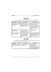
... drive type in ; Re-install applications and data using backup disks. Backing up the hard drive is scrambled. be defective. Reformat the hard drive. Damaged hard disk or disk controller. All hard disks are securely plugged in the standard CMOS setup. Make sure both DRIVE SPECIFICATION. Run the FDISK program, format the hard drive. disk may be behind this. Chapter 4 Trouble shooting Connector between hard When attempting to run Check cable running from drive and system board the FDISK utility...
... drive type in ; Re-install applications and data using backup disks. Backing up the hard drive is scrambled. be defective. Reformat the hard drive. Damaged hard disk or disk controller. All hard disks are securely plugged in the standard CMOS setup. Make sure both DRIVE SPECIFICATION. Run the FDISK program, format the hard drive. disk may be behind this. Chapter 4 Trouble shooting Connector between hard When attempting to run Check cable running from drive and system board the FDISK utility...

M7MKE user's manual
Page 75
... completed. Review system's equipment . No power to backup the hard format, partition, and high disk. Make sure monitor is in setup. Incorrect information entered into the configuration (setup) program. Check the configuration program. Replace any salvageable instead of causes could be behind this. Monitor not connected to display card. Check the power connectors to monitor and to system. See instructions above. Chapter 4 Trouble shooting A number of an image data. Use a file by file backup...
... completed. Review system's equipment . No power to backup the hard format, partition, and high disk. Make sure monitor is in setup. Incorrect information entered into the configuration (setup) program. Check the configuration program. Replace any salvageable instead of causes could be behind this. Monitor not connected to display card. Check the power connectors to monitor and to system. See instructions above. Chapter 4 Trouble shooting A number of an image data. Use a file by file backup...
M7MKE user's manual
Page 78
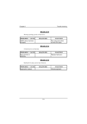
Replace keyboard. Keyboard is locked. Unlock keyboard. Keys jammed or defective. Trouble shooting Run setup and select correct drive type. Chapter 4 CMOS setup has been changed.
Replace keyboard. Keyboard is locked. Unlock keyboard. Keys jammed or defective. Trouble shooting Run setup and select correct drive type. Chapter 4 CMOS setup has been changed.


