

P4M80-M4 user's manual
Page 2
... 4 1.3 Layout and Components 5 Chapter 2: Hardware Installation 6 2.1 Installing Central Processing Unit (CPU 6 2.2 FAN Headers 7 2.3 Installing System Memory 8 2.4 Connectors and Slots 9 Chapter 3: Headers & Jumpers Setup 12 3.1 How to Setup Jumpers 12 3.2 Detail Settings 12 Chapter 4: Useful Help 18 4.1 Award BIOS Beep Code 18 4.2 Extra Information 18 4.3 Troubleshooting 20 Chapter 5: WarpSpeeder 21 5.1 Introduction 21 5.2 System Requirement 21 5.3 Installation 22 5.4 [WarpSpeeder™] includes 1 tray icon and 5 panels .......... 23...
... 4 1.3 Layout and Components 5 Chapter 2: Hardware Installation 6 2.1 Installing Central Processing Unit (CPU 6 2.2 FAN Headers 7 2.3 Installing System Memory 8 2.4 Connectors and Slots 9 Chapter 3: Headers & Jumpers Setup 12 3.1 How to Setup Jumpers 12 3.2 Detail Settings 12 Chapter 4: Useful Help 18 4.1 Award BIOS Beep Code 18 4.2 Extra Information 18 4.3 Troubleshooting 20 Chapter 5: WarpSpeeder 21 5.1 Introduction 21 5.2 System Requirement 21 5.3 Installation 22 5.4 [WarpSpeeder™] includes 1 tray icon and 5 panels .......... 23...

P4M80-M4 user's manual
Page 3
...not support Williamate CPU. Compliant with SATA Version 1.0 specification. - Data transfer rate up to 150 MB/s. 1 South Bridge: VIA VT8237R. Supports Intel Celeron/Celeron D processor. Dimensions ATX Form Factor: 20.2cm(W) x 24.4cm (L) Operating System Supporting Supports Windows 98SE, Windows NT, Windows 2000, Windows ME, Windows XP, Red-Hat Linux, and UNIX series. Supports RAID 0 and RAID 1 functions. System Memory Supports up to 2 DDR devices. P4M80-M4 CHAPTER 1: INTRODUCTION 1.1 MOTHERBOARD FEATURES A. Hardware CPU Supports Socket 478. Front Side Bus...
...not support Williamate CPU. Compliant with SATA Version 1.0 specification. - Data transfer rate up to 150 MB/s. 1 South Bridge: VIA VT8237R. Supports Intel Celeron/Celeron D processor. Dimensions ATX Form Factor: 20.2cm(W) x 24.4cm (L) Operating System Supporting Supports Windows 98SE, Windows NT, Windows 2000, Windows ME, Windows XP, Red-Hat Linux, and UNIX series. Supports RAID 0 and RAID 1 functions. System Memory Supports up to 2 DDR devices. P4M80-M4 CHAPTER 1: INTRODUCTION 1.1 MOTHERBOARD FEATURES A. Hardware CPU Supports Socket 478. Front Side Bus...
P4M80-M4 user's manual
Page 4
.../100/133 Bus Master Mode. P4M80-M4 Super I /O functionality. Supports ACPI and PCI power management. Compliant with AC'97 Version 2.3 specification. 10/100 LAN Chip: VIA VT6103L. Supports 10/100 Mb/s auto-negotiation operation. On Board AC'97 Sound Codec Chip: REALTEK ALC655. One AGP 4x/8x compatible slot. Provides the most commonly used legacy Super I /O Chip: ITE IT8705AF. Environment Control initiatives: H/W Monitor Fan Speed Controller ITE's "Smart Guardian" function On Board IDE Two on-board connectors support 4 devices. Supports SPDIF out function...
.../100/133 Bus Master Mode. P4M80-M4 Super I /O functionality. Supports ACPI and PCI power management. Compliant with AC'97 Version 2.3 specification. 10/100 LAN Chip: VIA VT6103L. Supports 10/100 Mb/s auto-negotiation operation. On Board AC'97 Sound Codec Chip: REALTEK ALC655. One AGP 4x/8x compatible slot. Provides the most commonly used legacy Super I /O Chip: ITE IT8705AF. Environment Control initiatives: H/W Monitor Fan Speed Controller ITE's "Smart Guardian" function On Board IDE Two on-board connectors support 4 devices. Supports SPDIF out function...
P4M80-M4 user's manual
Page 5
...-ROM audio-in connector. P4M80-M4 Internal On-board I /O Connectors 4 USB 2.0 ports. 1 VGA port. 1 Serial port. 1 Printer port. 1 RJ-45 LAN jack. 1 PS/2 Mouse port. 1 PS/2 Keyboard port. 1 vertical audio port including 1 line-in connector, 1 line-out connector, and 1 MIC-in device. 1 front audio header supports front panel audio-out function. 1 SPDIF-out connector supports digital audio-out function. 1 chassis open header supports PC case-opened warning function. 1 Floppy port supports 2 FDD with 360K, 720K, 1.2M, 1.44M and 2.88Mbytes. 2 IDE connectors support 4 hard disk devices. 2 Serial...
...-ROM audio-in connector. P4M80-M4 Internal On-board I /O Connectors 4 USB 2.0 ports. 1 VGA port. 1 Serial port. 1 Printer port. 1 RJ-45 LAN jack. 1 PS/2 Mouse port. 1 PS/2 Keyboard port. 1 vertical audio port including 1 line-in connector, 1 line-out connector, and 1 MIC-in device. 1 front audio header supports front panel audio-out function. 1 SPDIF-out connector supports digital audio-out function. 1 chassis open header supports PC case-opened warning function. 1 Floppy port supports 2 FDD with 360K, 720K, 1.2M, 1.44M and 2.88Mbytes. 2 IDE connectors support 4 hard disk devices. 2 Serial...
P4M80-M4 user's manual
Page 6
P4M80-M4 B. Software Supports Warpspeeder™, 9th Touch™, WINFLASHER™ and FLASHER™. 1.2 PACKAGE CHECKLIST FDD Cable X 1 HDD Cable X 1 User's Manual X 1 Fully Setup Driver CD X 1 USB 2.0 Cable X1 (optional) Serial ATA Cable X 2 (optional) SPDIF out Cable X 1 (optional) Rear I/O Panel for ATX Case X 1 4 BIOS & Software BIOS Award legal BIOS. Supports ACPI Supports USB Function. Supports APM1.2.
P4M80-M4 B. Software Supports Warpspeeder™, 9th Touch™, WINFLASHER™ and FLASHER™. 1.2 PACKAGE CHECKLIST FDD Cable X 1 HDD Cable X 1 User's Manual X 1 Fully Setup Driver CD X 1 USB 2.0 Cable X1 (optional) Serial ATA Cable X 2 (optional) SPDIF out Cable X 1 (optional) Rear I/O Panel for ATX Case X 1 4 BIOS & Software BIOS Award legal BIOS. Supports ACPI Supports USB Function. Supports APM1.2.

P4M80-M4 user's manual
Page 7
JATXPWR1 P4M80-M4 1.3 LAYOUT AND COMPONENTS JKBMS1 PU Socket 478 JCOM1 CPU1 JCFAN1 JPRNT JVGA1 DIMM1 DIMM2 JUSB1 JATXPWR2 IDE1 IDE2 JUSBLAN1 JAUDIO Super I/O BIOS P4M800 AGP1 LAN JAUDIO1 JCDIN1 JAUX1 (optional) Codec PCI1 JSPDIFO1 CNR1 PCI2 PCI3 JUSB3 JUSB4 BAT1 VT8237R JSATA2 JSATA1 FDD1 JSFAN1 JCMOS1 JCI1 JPANEL1 Note: ■ represents the 1st pin. 5
JATXPWR1 P4M80-M4 1.3 LAYOUT AND COMPONENTS JKBMS1 PU Socket 478 JCOM1 CPU1 JCFAN1 JPRNT JVGA1 DIMM1 DIMM2 JUSB1 JATXPWR2 IDE1 IDE2 JUSBLAN1 JAUDIO Super I/O BIOS P4M800 AGP1 LAN JAUDIO1 JCDIN1 JAUX1 (optional) Codec PCI1 JSPDIFO1 CNR1 PCI2 PCI3 JUSB3 JUSB4 BAT1 VT8237R JSATA2 JSATA1 FDD1 JSFAN1 JCMOS1 JCI1 JPANEL1 Note: ■ represents the 1st pin. 5

P4M80-M4 user's manual
Page 8
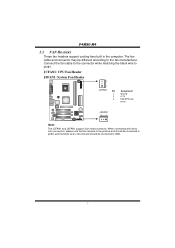
The CPU will fit only in the correct orientation. Connect the CPU FAN power cable to complete the installation. Step 3: Hold the CPU down firmly, and then close the lever to the JCFAN1. Step 2: Look for the white dot/cut edge should point wards the lever pivot. Step 4: Put the CPU Fan on the CPU and buckle it. P4M80-M4 CHAPTER 2: HARDWARE INSTALLATION 2.1 INSTALLING CENTRAL PROCESSING UNIT (CPU) PU PU Step 1: Pull the lever sideways away from the socket and then raise the lever up to a 90-degree angle. This completes the installation. 6 The white dot/cut edge.
The CPU will fit only in the correct orientation. Connect the CPU FAN power cable to complete the installation. Step 3: Hold the CPU down firmly, and then close the lever to the JCFAN1. Step 2: Look for the white dot/cut edge should point wards the lever pivot. Step 4: Put the CPU Fan on the CPU and buckle it. P4M80-M4 CHAPTER 2: HARDWARE INSTALLATION 2.1 INSTALLING CENTRAL PROCESSING UNIT (CPU) PU PU Step 1: Pull the lever sideways away from the socket and then raise the lever up to a 90-degree angle. This completes the installation. 6 The white dot/cut edge.
P4M80-M4 user's manual
Page 9
... JCFAN1 and JSFAN1 support 3-pin head connector. When connecting with wires onto connectors, please note that the red wire is the positive and should be connected to pin#2, and the black wire is Ground and should be different according to the fan manufacturer. Connect the fan cable to the connector while matching the black wire to GND. 7 The fan cable and connector may be connected to pin#1. P4M80-M4 2.2 FAN HEADERS These fan headers support cooling-fans built in...
... JCFAN1 and JSFAN1 support 3-pin head connector. When connecting with wires onto connectors, please note that the red wire is the positive and should be connected to pin#2, and the black wire is Ground and should be different according to the fan manufacturer. Connect the fan cable to the connector while matching the black wire to GND. 7 The fan cable and connector may be connected to pin#1. P4M80-M4 2.2 FAN HEADERS These fan headers support cooling-fans built in...
P4M80-M4 user's manual
Page 11
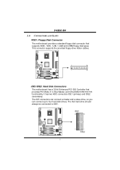
... PCI IDE Controller that supports 360K, 720K, 1.2M, 1.44M and 2.88M floppy disk types. The IDE connectors can connect a master and a slave drive, so you can connect up to IDE1. It has two HDD connectors IDE1 (primary) and IDE2 (secondary). This connector supports the provided floppy drive ribbon cables. PU IDE1 40 39 2 1 IDE2 9 The first hard drive should always be connected to four hard disk drives. P4M80-M4 2.4 CONNECTORS AND SLOTS FDD1: Floppy Disk Connector The motherboard provides a standard floppy disk connector that provides PIO Mode 0~4, Bus...
... PCI IDE Controller that supports 360K, 720K, 1.2M, 1.44M and 2.88M floppy disk types. The IDE connectors can connect a master and a slave drive, so you can connect up to IDE1. It has two HDD connectors IDE1 (primary) and IDE2 (secondary). This connector supports the provided floppy drive ribbon cables. PU IDE1 40 39 2 1 IDE2 9 The first hard drive should always be connected to four hard disk drives. P4M80-M4 2.4 CONNECTORS AND SLOTS FDD1: Floppy Disk Connector The motherboard provides a standard floppy disk connector that provides PIO Mode 0~4, Bus...
P4M80-M4 user's manual
Page 12
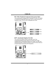
... it is designated as 32 bits. P4M80-M4 PCI1~PCI3: Peripheral Component Interconnect Slots This motherboard is equipped with an Accelerated Graphics Port (AGP). PU PCI1 PCI2 PCI3 AGP1: Accelerated Graphics Port Slot Your monitor will take advantage of AGP technology for expansion cards. An AGP card will attach directly to that video card. This motherboard supports video cards for PCI slots, but it is a bus standard for improved video efficiency and performance, especially...
... it is designated as 32 bits. P4M80-M4 PCI1~PCI3: Peripheral Component Interconnect Slots This motherboard is equipped with an Accelerated Graphics Port (AGP). PU PCI1 PCI2 PCI3 AGP1: Accelerated Graphics Port Slot Your monitor will take advantage of AGP technology for expansion cards. An AGP card will attach directly to that video card. This motherboard supports video cards for PCI slots, but it is a bus standard for improved video efficiency and performance, especially...

P4M80-M4 user's manual
Page 14
P4M80-M4 CHAPTER 3: HEADERS & JUMPERS SETUP 3.1 HOW TO SETUP JUMPERS The illustration shows how to connect 20-pin power connector on pins, the jumper is "close", if not, that means the jumper is "open". When the jumper cap is placed on the ATX power supply. Pin Assignment 1 +3.3V 2 +3.3V 3 Ground PU 4 +5V 12 24 5 Ground 6 +5V 7 Ground 8 PW_OK 9 Standby Voltage +5V 10 +12V 11 +3.3V 12 -12V 13 Ground 1 13 14...
P4M80-M4 CHAPTER 3: HEADERS & JUMPERS SETUP 3.1 HOW TO SETUP JUMPERS The illustration shows how to connect 20-pin power connector on pins, the jumper is "close", if not, that means the jumper is "open". When the jumper cap is placed on the ATX power supply. Pin Assignment 1 +3.3V 2 +3.3V 3 Ground PU 4 +5V 12 24 5 Ground 6 +5V 7 Ground 8 PW_OK 9 Standby Voltage +5V 10 +12V 11 +3.3V 12 -12V 13 Ground 1 13 14...

P4M80-M4 user's manual
Page 15
P4M80-M4 JATXPWR2: ATX Power Connector By connecting this connector, it will disable the output on back panel audio connectors. Pin Assignment 1 Mic in/center 2 Ground 3 Mic power/Bass 4 Audio power 5 Right line PU out/Speaker out Right 6 Right line out/Speaker out Right 7 Reserved 8 Key 9 Left line out/Speaker out Left 2 14 10 Left line out/Speaker out Left 1 13 11 Right line in/Rear speaker Right 12 Right line in...
P4M80-M4 JATXPWR2: ATX Power Connector By connecting this connector, it will disable the output on back panel audio connectors. Pin Assignment 1 Mic in/center 2 Ground 3 Mic power/Bass 4 Audio power 5 Right line PU out/Speaker out Right 6 Right line out/Speaker out Right 7 Reserved 8 Key 9 Left line out/Speaker out Left 2 14 10 Left line out/Speaker out Left 1 13 11 Right line in/Rear speaker Right 12 Right line in...

P4M80-M4 user's manual
Page 16
P4M80-M4 JSPDIFO1: Digital Audio-out Connector This connector allows user to connect the PC case's front panel switch functions. PU PWR_LED SLP On/Off IR ++ - 2 24 1 +- 23 SPK RST IR HLED Pin Assignment 1 +5V 3 N/A 5 N/A 7 Speaker 9 HDD LED (+) 11 HDD LED (-) 13 Ground 15 Reset control 17 N/A 19 N/A 21 +5V 23 IRTX Function Pin Assignment 2 Sleep control Speaker Connector 4 Ground 6 N/A 8 Power LED (+) Hard drive LED 10 Power LED (+) 12 Power LED (-) Reset button 14 Power button 16 Ground 18 Key IrDA Connector 20 Key 22 Ground 24 IRRX ...
P4M80-M4 JSPDIFO1: Digital Audio-out Connector This connector allows user to connect the PC case's front panel switch functions. PU PWR_LED SLP On/Off IR ++ - 2 24 1 +- 23 SPK RST IR HLED Pin Assignment 1 +5V 3 N/A 5 N/A 7 Speaker 9 HDD LED (+) 11 HDD LED (-) 13 Ground 15 Reset control 17 N/A 19 N/A 21 +5V 23 IRTX Function Pin Assignment 2 Sleep control Speaker Connector 4 Ground 6 N/A 8 Power LED (+) Hard drive LED 10 Power LED (+) 12 Power LED (-) Reset button 14 Power button 16 Ground 18 Key IrDA Connector 20 Key 22 Ground 24 IRRX ...
P4M80-M4 user's manual
Page 17
... be connected with internal USB devices, like USB card reader. Set the jumper to "Pin 1-2 close ". 3. Reset your desired password or clear the CMOS data. 15 Set the jumper to "Pin 2-3 close ". 5. P4M80-M4 JUSB3/JUSB4: Front USB Headers This motherboard provides 2 USB 2.0 headers, which allows user to connect additional USB cable on the AC. 6. Remove AC power line. 2. PU 13 Pin 1-2 Close: Normal Operation (default). 13 Pin 2-3 Close: 1 3 Clear CMOS data. ※ Clear CMOS Procedures: 1. PU Pin Assignment 1 +5V (fused) 2 +5V (fused) 3 USB- 4 USB- 2 10 JUSB3 5 USB+ 6 USB...
... be connected with internal USB devices, like USB card reader. Set the jumper to "Pin 1-2 close ". 3. Reset your desired password or clear the CMOS data. 15 Set the jumper to "Pin 2-3 close ". 5. P4M80-M4 JUSB3/JUSB4: Front USB Headers This motherboard provides 2 USB 2.0 headers, which allows user to connect additional USB cable on the AC. 6. Remove AC power line. 2. PU 13 Pin 1-2 Close: Normal Operation (default). 13 Pin 2-3 Close: 1 3 Clear CMOS data. ※ Clear CMOS Procedures: 1. PU Pin Assignment 1 +5V (fused) 2 +5V (fused) 3 USB- 4 USB- 2 10 JUSB3 5 USB+ 6 USB...
P4M80-M4 user's manual
Page 18
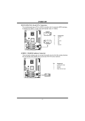
P4M80-M4 JSATA1/JSATA2: Serial ATA Connectors The motherboard has a PCI to connect the audio source from the variety devices, like CD-ROM, DVD-ROM, PCI sound card, PCI TV turner card etc.. PU Pin Assignment 1 Left channel input 2 Ground 3 Ground 4 Right channel input 4 1 16 PU JSATA2 7 41 1 47 JSATA1 Pin Assignment 1 Ground 2 TX+ 3 TX- 4 Ground 5 RX- 6 RX+ 7 Ground JCDIN1: CD-ROM Audio-in Connector This connector allows user to SATA Controller with 2 channels SATA interface, it satisfies the SATA 1.0 spec and with transfer rate of 1.5Gb/s.
P4M80-M4 JSATA1/JSATA2: Serial ATA Connectors The motherboard has a PCI to connect the audio source from the variety devices, like CD-ROM, DVD-ROM, PCI sound card, PCI TV turner card etc.. PU Pin Assignment 1 Left channel input 2 Ground 3 Ground 4 Right channel input 4 1 16 PU JSATA2 7 41 1 47 JSATA1 Pin Assignment 1 Ground 2 TX+ 3 TX- 4 Ground 5 RX- 6 RX+ 7 Ground JCDIN1: CD-ROM Audio-in Connector This connector allows user to SATA Controller with 2 channels SATA interface, it satisfies the SATA 1.0 spec and with transfer rate of 1.5Gb/s.
P4M80-M4 user's manual
Page 20
... Short beep when system boot-up Long beeps every other second Meaning Video card not found or video card memory bad CPU overheated System will boo-up the system, it means the BIOS contents are corrupted. P4M80-M4 CHAPTER 4: USEFUL HELP 4.1 AWARD BIOS BEEP CODE Beep Sound One long beep followed by virus, the Boot-Block function will help to restore BIOS. Make a bootable floppy disk. 2. The BIOS has been recovered and will update BIOS automatically and restart. 9. System will work...
... Short beep when system boot-up Long beeps every other second Meaning Video card not found or video card memory bad CPU overheated System will boo-up the system, it means the BIOS contents are corrupted. P4M80-M4 CHAPTER 4: USEFUL HELP 4.1 AWARD BIOS BEEP CODE Beep Sound One long beep followed by virus, the Boot-Block function will help to restore BIOS. Make a bootable floppy disk. 2. The BIOS has been recovered and will update BIOS automatically and restart. 9. System will work...

P4M80-M4 user's manual
Page 21
... a damage of the CPU, and the system may not power on again. P4M80-M4 B. CPU Overheated If the system shutdown automatically after power on the system again. 19 In this case, please double check: 1. Remove the power cord from power supply for seconds, that means the CPU protection function has been activated. Clear the CMOS data. (See "Close CMOS Header: JCMOS1" section) 2. Power on system for seconds...
... a damage of the CPU, and the system may not power on again. P4M80-M4 B. CPU Overheated If the system shutdown automatically after power on the system again. 19 In this case, please double check: 1. Remove the power cord from power supply for seconds, that means the CPU protection function has been activated. Clear the CMOS data. (See "Close CMOS Header: JCMOS1" section) 2. Power on system for seconds...

P4M80-M4 user's manual
Page 22
...used but booting from optical drive. 1. Screen message says "Invalid Configuration" or "CMOS Failure." inside power supply does not turn on . 3. Run SETUP program and select correct drive types. Contact technical support. 2. drive, can be booted from optical drive. 2. on . Keyboard lights are on both ends are capable of the DIMM, press down at all 1. All hard disks are securely plugged in the standard CMOS setup. Replace cable. is Power light don't illuminate, fan securely plugged in setup. P4M80-M4 4.3 TROUBLESHOOTING Probable Solution 1. Re-install...
...used but booting from optical drive. 1. Screen message says "Invalid Configuration" or "CMOS Failure." inside power supply does not turn on . 3. Run SETUP program and select correct drive types. Contact technical support. 2. drive, can be booted from optical drive. 2. on . Keyboard lights are on both ends are capable of the DIMM, press down at all 1. All hard disks are securely plugged in the standard CMOS setup. Replace cable. is Power light don't illuminate, fan securely plugged in setup. P4M80-M4 4.3 TROUBLESHOOTING Probable Solution 1. Re-install...
P4M80-M4 user's manual
Page 23
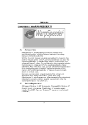
... restart to power up CPU core voltage and Memory voltage. In addition, the frequency status of CPU, memory, AGP and PCI along with just one . 5.2 SYSTEM REQUIREMENT OS Support: Windows 98 SE, Windows Me, Windows 2000, Windows XP DirectX: DirectX 8.1 or above. (The Windows XP operating system includes DirectX 8.1. The Overvoltage Manager, on our main panel. If you use Windows XP, you can get detail descriptions about BIOS model and chipsets. P4M80-M4 CHAPTER 5: WARPSPEEDER...
... restart to power up CPU core voltage and Memory voltage. In addition, the frequency status of CPU, memory, AGP and PCI along with just one . 5.2 SYSTEM REQUIREMENT OS Support: Windows 98 SE, Windows Me, Windows 2000, Windows XP DirectX: DirectX 8.1 or above. (The Windows XP operating system includes DirectX 8.1. The Overvoltage Manager, on our main panel. If you use Windows XP, you can get detail descriptions about BIOS model and chipsets. P4M80-M4 CHAPTER 5: WARPSPEEDER...

P4M80-M4 user's manual
Page 29
... Monitor panel will proceed a testing for Direct3D rendering. 5. P4M80-M4 c. "Auto-overclock button": User can click this panel, you can click this button and [WarpSpeeder™] will slide out to left as the following figure. Then system will restore to the hardware default setting or load the verified best and stable frequency according to the Recovery Dialog's setting. After reboot, the [WarpSpeeder™] utility will do a fail-safe...
... Monitor panel will proceed a testing for Direct3D rendering. 5. P4M80-M4 c. "Auto-overclock button": User can click this panel, you can click this button and [WarpSpeeder™] will slide out to left as the following figure. Then system will restore to the hardware default setting or load the verified best and stable frequency according to the Recovery Dialog's setting. After reboot, the [WarpSpeeder™] utility will do a fail-safe...


