Setup Manual
Page 1
TA790GX3 A2+ Setup Manual FCC Information and Copyright This equipment has been tested and found in this user's manual. The vendor makes no guarantee that interference will not be changed without notice and we will not occur in a particular installation. Further the... harmful interference in whole, is no representations or warranties with respect to be responsible for any party beforehand. The content of this user's manual is subject to the contents here and specially disclaims any mistakes found to comply with the instructions, may cause harmful interference to Part 15 ...
TA790GX3 A2+ Setup Manual FCC Information and Copyright This equipment has been tested and found in this user's manual. The vendor makes no guarantee that interference will not be changed without notice and we will not occur in a particular installation. Further the... harmful interference in whole, is no representations or warranties with respect to be responsible for any party beforehand. The content of this user's manual is subject to the contents here and specially disclaims any mistakes found to comply with the instructions, may cause harmful interference to Part 15 ...
Setup Manual
Page 3
...dry and stable working environment with sufficient lighting. „ Always disconnect the computer from power outlet before operation. „ Before you for ATX Case X 1 User's Manual X 1 Fully Setup Driver CD X 1 FDD Cable X 1 (optional) USB 2.0 Cable X1 (optional) S/PDIF out Cable X 1 (optional) Note: The ... „ Avoid touching the components on motherboard or the rear side of the board unless necessary. CHAPTER 1: INTRODUCTION TA790GX3 A2+ 1.1 BEFORE YOU START Thank you take the motherboard out from anti-static bag, ground yourself properly by area or your motherboard version. ...
...dry and stable working environment with sufficient lighting. „ Always disconnect the computer from power outlet before operation. „ Before you for ATX Case X 1 User's Manual X 1 Fully Setup Driver CD X 1 FDD Cable X 1 (optional) USB 2.0 Cable X1 (optional) S/PDIF out Cable X 1 (optional) Note: The ... „ Avoid touching the components on motherboard or the rear side of the board unless necessary. CHAPTER 1: INTRODUCTION TA790GX3 A2+ 1.1 BEFORE YOU START Thank you take the motherboard out from anti-static bag, ground yourself properly by area or your motherboard version. ...
Setup Manual
Page 4
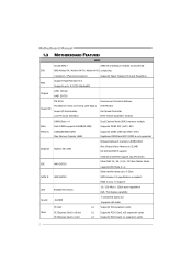
... (by ATI driver) IDE AMD SB750 Ultra DMA 33 / 66 / 100 / 133 Bus Master Mode supports PIO Mode 0~4, Data transfer rates up to 3 Gb/s. Motherboard Manual 1.3 MOTHERBOARD FEATURES SPEC Socket AM2+ AMD 64 Architecture enables 32 and 64 bit CPU AMD Athlon 64 / Athlon 64 FX / Athlon 64 X2 computing / Sempron...
... (by ATI driver) IDE AMD SB750 Ultra DMA 33 / 66 / 100 / 133 Bus Master Mode supports PIO Mode 0~4, Data transfer rates up to 3 Gb/s. Motherboard Manual 1.3 MOTHERBOARD FEATURES SPEC Socket AM2+ AMD 64 Architecture enables 32 and 64 bit CPU AMD Athlon 64 / Athlon 64 FX / Athlon 64 X2 computing / Sempron...
Setup Manual
Page 6
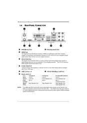
Motherboard Manual 1.4 REAR PANEL CONNECTORS X PS/2 Mouse Port Y PS/2 Keyboard Port Z HDMI Port The High-Definition Multimedia Interface (HDMI) is a video interface transmitting digital video signals to ...
Motherboard Manual 1.4 REAR PANEL CONNECTORS X PS/2 Mouse Port Y PS/2 Keyboard Port Z HDMI Port The High-Definition Multimedia Interface (HDMI) is a video interface transmitting digital video signals to ...
Setup Manual
Page 8
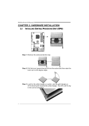
Step 3: Look for the white triangle on socket, and the gold triangle on CPU should point towards this white triangle. Motherboard Manual CHAPTER 2: HARDWARE INSTALLATION 2.1 INSTALLING CENTRAL PROCESSING UNIT (CPU) Step 1: Remove the socket protection cap. Step 2: Pull the lever toward direction A from the socket and then raise the lever up to a 90-degree angle. The CPU will fit only in the correct orientation. 6
Step 3: Look for the white triangle on socket, and the gold triangle on CPU should point towards this white triangle. Motherboard Manual CHAPTER 2: HARDWARE INSTALLATION 2.1 INSTALLING CENTRAL PROCESSING UNIT (CPU) Step 1: Remove the socket protection cap. Step 2: Pull the lever toward direction A from the socket and then raise the lever up to a 90-degree angle. The CPU will fit only in the correct orientation. 6
Setup Manual
Page 10
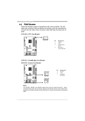
Motherboard Manual 2.2 FAN HEADERS These fan headers support cooling-fans built in the computer. When connecting with wires onto connectors, please note that the red wire is ...
Motherboard Manual 2.2 FAN HEADERS These fan headers support cooling-fans built in the computer. When connecting with wires onto connectors, please note that the red wire is ...
Setup Manual
Page 12
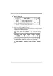
Motherboard Manual B. C. Memory Capacity DIMM Socket Location DIMMA1 DIMMB1 DIMMA2 DIMMB2 DDR2 Module 256MB/512MB/1GB/2GB/4GB 256MB/512MB/1GB/2GB/4GB 256MB/512MB/1GB/2GB/...
Motherboard Manual B. C. Memory Capacity DIMM Socket Location DIMMA1 DIMMB1 DIMMA2 DIMMB2 DDR2 Module 256MB/512MB/1GB/2GB/4GB 256MB/512MB/1GB/2GB/4GB 256MB/512MB/1GB/2GB/...

Setup Manual
Page 14
... supports dual PCI-Express graphics cards using CrossFireX technology with x8 speed. - The design of 4GB/s simultaneously per direction, for graphics or video cards. Motherboard Manual PEX16_1: PCI-Express Gen2 x16 Slot (x16/x8 Speed) - To make PEX16_1 run with multiple displays.
... supports dual PCI-Express graphics cards using CrossFireX technology with x8 speed. - The design of 4GB/s simultaneously per direction, for graphics or video cards. Motherboard Manual PEX16_1: PCI-Express Gen2 x16 Slot (x16/x8 Speed) - To make PEX16_1 run with multiple displays.
Setup Manual
Page 16
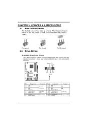
It allows user to set up jumpers. When the jumper cap is "open". Motherboard Manual CHAPTER 3: HEADERS & JUMPERS SETUP 3.1 HOW TO SETUP JUMPERS The illustration shows how to connect the PC case's front panel switch functions. PWR_LE D On/Off ++- 9 16 1 +- 8 ...
It allows user to set up jumpers. When the jumper cap is "open". Motherboard Manual CHAPTER 3: HEADERS & JUMPERS SETUP 3.1 HOW TO SETUP JUMPERS The illustration shows how to connect the PC case's front panel switch functions. PWR_LE D On/Off ++- 9 16 1 +- 8 ...
Setup Manual
Page 18
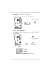
... better graphics performance. Remove AC power line. 2. Set the jumper to "Pin 1-2 close ". 3. Set the jumper to "Pin 2-3 close ". 5. Exclusive power for five seconds. 4. Motherboard Manual JATXPWR1: Auxiliary Power for Graphics This connector is an auxiliary power connection for graphics cards. Reset your desired password or clear the CMOS data. 16...
... better graphics performance. Remove AC power line. 2. Set the jumper to "Pin 1-2 close ". 3. Set the jumper to "Pin 2-3 close ". 5. Exclusive power for five seconds. 4. Motherboard Manual JATXPWR1: Auxiliary Power for Graphics This connector is an auxiliary power connection for graphics cards. Reset your desired password or clear the CMOS data. 16...
Setup Manual
Page 20
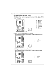
Motherboard Manual JAUDIOF1: Front Panel Audio Header This header allows user to connect the PCI bracket SPDIF input header. AC'97 connector is not acceptable. 2 10 Pin ...
Motherboard Manual JAUDIOF1: Front Panel Audio Header This header allows user to connect the PCI bracket SPDIF input header. AC'97 connector is not acceptable. 2 10 Pin ...
Setup Manual
Page 22
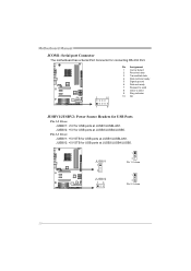
Motherboard Manual JCOM1: Serial port Connector The motherboard has a Serial Port Connector for connecting RS-232 Port. 2 10 Pin Assignment 1 Carrier detect 2 Received data 3 Transmitted data 4 Data ...
Motherboard Manual JCOM1: Serial port Connector The motherboard has a Serial Port Connector for connecting RS-232 Port. 2 10 Pin Assignment 1 Carrier detect 2 Received data 3 Transmitted data 4 Data ...
Setup Manual
Page 24
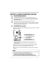
... with Radeon HD3650/HD3850/HD3870/HD4850/ HD4870/HD3870X2 GPU. Step 2: Connect a 4-pin ATX power cable to Auxiliary Power Connector (JATXPWR1), this will be unstable. Motherboard Manual CHAPTER 4: (HYBRID) CROSSFIREX FUNCTION 4.1 CROSSFIREX REQUIREMENTS Only Windows XP/Vista supports CrossFireX (Dual Video) function. NOTE For more detail information of hardware/software installation and...
... with Radeon HD3650/HD3850/HD3870/HD4850/ HD4870/HD3870X2 GPU. Step 2: Connect a 4-pin ATX power cable to Auxiliary Power Connector (JATXPWR1), this will be unstable. Motherboard Manual CHAPTER 4: (HYBRID) CROSSFIREX FUNCTION 4.1 CROSSFIREX REQUIREMENTS Only Windows XP/Vista supports CrossFireX (Dual Video) function. NOTE For more detail information of hardware/software installation and...
Setup Manual
Page 26
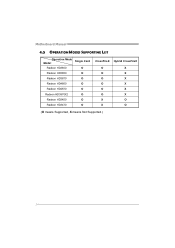
Motherboard Manual 4.5 OPERATION MODES SUPPORTING LIST Operation Mode Single Card Model Radeon HD3650 O Radeon HD3850 O Radeon HD3870 O Radeon HD4850 O Radeon HD4870 O Radeon HD3870X2 O Radeon HD3450 O Radeon HD3470 O CrossFireX Hybrid CrossFireX O X O X O X O X O X O X X O X O (O means Supported, X means Not Supported.) 24
Motherboard Manual 4.5 OPERATION MODES SUPPORTING LIST Operation Mode Single Card Model Radeon HD3650 O Radeon HD3850 O Radeon HD3870 O Radeon HD4850 O Radeon HD4870 O Radeon HD3870X2 O Radeon HD3450 O Radeon HD3470 O CrossFireX Hybrid CrossFireX O X O X O X O X O X O X X O X O (O means Supported, X means Not Supported.) 24
Setup Manual
Page 28
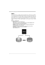
Motherboard Manual RAID 1: Every read and write is actually carried out in parallel across 2 disk drives in the array. RAID techniques can reside on the same disk ... drive. Drawbacks: Requires 2 drives for the storage space of the data can be applied for small databases or any other application that eliminates tedious manual backups to more expensive and less reliable media. Should one drive.
Motherboard Manual RAID 1: Every read and write is actually carried out in parallel across 2 disk drives in the array. RAID techniques can reside on the same disk ... drive. Drawbacks: Requires 2 drives for the storage space of the data can be applied for small databases or any other application that eliminates tedious manual backups to more expensive and less reliable media. Should one drive.
Setup Manual
Page 30
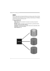
Motherboard Manual RAID 5: RAID 5 stripes both data and parity information across all the drives in the array. It writes data and parity blocks across three or more ...
Motherboard Manual RAID 5: RAID 5 stripes both data and parity information across all the drives in the array. It writes data and parity blocks across three or more ...

Setup Manual
Page 31
... Memory Configuration > EC Configuration GFX Engine Clock Override [Disabled] Integrated Memory Test [Disabled] Options Normal Automate OverClock Manual OverClock Select Screen Select Item +- The BIOS information described below sections may be different from USB Flash Drive or ... the Setup CD. A. TA790GX3 A2+ CHAPTER 6: T-SERIES BIOS & SOFTWARE 6.1 T-SERIES BIOS T-Series BIOS Features Overclocking Navigator Engine (O.N.E.) Memory Integration Test (M.I.T., under Overclock Navigator Engine) BIO-Flasher: Update BIOS file from this manual. For better system performance,...
... Memory Configuration > EC Configuration GFX Engine Clock Override [Disabled] Integrated Memory Test [Disabled] Options Normal Automate OverClock Manual OverClock Select Screen Select Item +- The BIOS information described below sections may be different from USB Flash Drive or ... the Setup CD. A. TA790GX3 A2+ CHAPTER 6: T-SERIES BIOS & SOFTWARE 6.1 T-SERIES BIOS T-Series BIOS Features Overclocking Navigator Engine (O.N.E.) Memory Integration Test (M.I.T., under Overclock Navigator Engine) BIO-Flasher: Update BIOS file from this manual. For better system performance,...
Setup Manual
Page 32
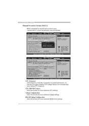
...> Memory Configuration > EC Configuration GFX Engine Clock Override [Disabled] Integrated Memory Test [Disabled] Options Normal Automate OverClock Manual OverClock Select Screen Select Item +- CPU Frequency CPU Frequency is designed for more advanced CPU settings. Voltage Configuration Enter this... > Memory Configuration > EC Configuration GFX Engine Clock Override [Disabled] Integrated Memory Test [Disabled] Options Normal Automate OverClock Manual OverClock Select Screen Select Item +- To maintain the system stability, CPU voltage needs to system performance. Change Option F1 ...
...> Memory Configuration > EC Configuration GFX Engine Clock Override [Disabled] Integrated Memory Test [Disabled] Options Normal Automate OverClock Manual OverClock Select Screen Select Item +- CPU Frequency CPU Frequency is designed for more advanced CPU settings. Voltage Configuration Enter this... > Memory Configuration > EC Configuration GFX Engine Clock Override [Disabled] Integrated Memory Test [Disabled] Options Normal Automate OverClock Manual OverClock Select Screen Select Item +- To maintain the system stability, CPU voltage needs to system performance. Change Option F1 ...
Setup Manual
Page 33
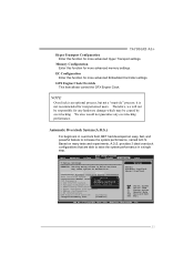
... Normal Automate OverClock Manual OverClock Select Screen Select Item +- Change Option F1 General Help F10 Save and Exit ESC Exit vxx.xx (C)Copyright 1985-200x, American Megatrends, Inc. 31 Therefore, we will not be caused by overclocking. Memory Configuration Enter this function for more advanced Hyper Transport settings. TA790GX3 A2+ Hyper Transport Configuration...
... Normal Automate OverClock Manual OverClock Select Screen Select Item +- Change Option F1 General Help F10 Save and Exit ESC Exit vxx.xx (C)Copyright 1985-200x, American Megatrends, Inc. 31 Therefore, we will not be caused by overclocking. Memory Configuration Enter this function for more advanced Hyper Transport settings. TA790GX3 A2+ Hyper Transport Configuration...
Setup Manual
Page 34
...system to malfunction. OverClock Navigator [Automate OverClock] =========== Automate OverClock System =========== Auto OverClock System [V8-Tech Engine] Manual OverClock System CPU Frequency [200] > CPU FID/VID Control > Voltage Configuration > DRAM Timing Configuration > Hyper ...system to malfunction. OverClock Navigator [Automate OverClock] =========== Automate OverClock System =========== Auto OverClock System [V6-Tech Engine] Manual OverClock System CPU Frequency [200] > CPU FID/VID Control > Voltage Configuration > DRAM Timing Configuration > Hyper ...
...system to malfunction. OverClock Navigator [Automate OverClock] =========== Automate OverClock System =========== Auto OverClock System [V8-Tech Engine] Manual OverClock System CPU Frequency [200] > CPU FID/VID Control > Voltage Configuration > DRAM Timing Configuration > Hyper ...system to malfunction. OverClock Navigator [Automate OverClock] =========== Automate OverClock System =========== Auto OverClock System [V6-Tech Engine] Manual OverClock System CPU Frequency [200] > CPU FID/VID Control > Voltage Configuration > DRAM Timing Configuration > Hyper ...

