Setup Manual
Page 2
... (CPU 6 2.2 FAN Headers 8 2.3 Installing System Memory 9 2.4 Connectors and Slots 11 Chapter 3: Headers & Jumpers Setup 14 3.1 How to Setup Jumpers 14 3.2 Detail Settings 14 Chapter 4: (Hybrid) CrossFireX Function 22 4.1 CrossFireX Requirements 22 4.2 CrossFireX Installation 22 4.3 Hybrid CrossFireX Requirements 23 4.4 Hybrid CrossFireX Installation 23 4.5 Operation Modes Supporting List 24 Chapter 5: RAID Functions 25 5.1 Operation System 25 5.2 Raid Arrays 25 5.3 How RAID Works 25 Chapter 6: T-Series BIOS & Software 29 6.1 T-Series BIOS 29...
... (CPU 6 2.2 FAN Headers 8 2.3 Installing System Memory 9 2.4 Connectors and Slots 11 Chapter 3: Headers & Jumpers Setup 14 3.1 How to Setup Jumpers 14 3.2 Detail Settings 14 Chapter 4: (Hybrid) CrossFireX Function 22 4.1 CrossFireX Requirements 22 4.2 CrossFireX Installation 22 4.3 Hybrid CrossFireX Requirements 23 4.4 Hybrid CrossFireX Installation 23 4.5 Operation Modes Supporting List 24 Chapter 5: RAID Functions 25 5.1 Operation System 25 5.2 Raid Arrays 25 5.3 How RAID Works 25 Chapter 6: T-Series BIOS & Software 29 6.1 T-Series BIOS 29...
Setup Manual
Page 4
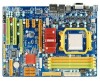
... PCI-E Gen2 x1 expansion cards 2 SATA II AMD SB750 SATA Version 2.0 specification compliant. Motherboard Manual 1.3 MOTHERBOARD FEATURES SPEC Socket AM2+ AMD 64 Architecture enables 32 and 64 bit CPU AMD Athlon 64 / Athlon 64 FX / Athlon 64 X2 computing / Sempron / Phenom processors Supports Hyper Transport 3.0 and PowerNow Support HyperTransport 3.0 FSB Supports up to 5.2 GT/s Bandwidth Chipset AMD 790GX AMD SB750 ITE 8718 Environment Control initiatives, Provides the most commonly used legacy Super I/O Super I/O functionality. H/W Monitor Fan Speed Controller Low Pin...
... PCI-E Gen2 x1 expansion cards 2 SATA II AMD SB750 SATA Version 2.0 specification compliant. Motherboard Manual 1.3 MOTHERBOARD FEATURES SPEC Socket AM2+ AMD 64 Architecture enables 32 and 64 bit CPU AMD Athlon 64 / Athlon 64 FX / Athlon 64 X2 computing / Sempron / Phenom processors Supports Hyper Transport 3.0 and PowerNow Support HyperTransport 3.0 FSB Supports up to 5.2 GT/s Bandwidth Chipset AMD 790GX AMD SB750 ITE 8718 Environment Control initiatives, Provides the most commonly used legacy Super I/O Super I/O functionality. H/W Monitor Fan Speed Controller Low Pin...
Setup Manual
Page 5
... connector Printer Port connector IDE Connector SATA Connector Front Panel Connector Front Audio Connector CD-in Connector On Board S/PDIF out connector Connector S/PDIF in connector CPU Fan header System Fan header CMOS clear header USB connector Serial port Connector Power Connector (24pin) Power Connector (4pin) PS/2 Keyboard PS/2 Mouse HDMI port Back Panel VGA port I/O DVI-D port LAN port USB Port Audio Jack Board Size 225 mm (W) x 305 mm (L) OS Support Windows XP / VISTA TA790GX3 A2+ SPEC x1 Each connector supports 2 Floppy drives x1 Each connector supports...
... connector Printer Port connector IDE Connector SATA Connector Front Panel Connector Front Audio Connector CD-in Connector On Board S/PDIF out connector Connector S/PDIF in connector CPU Fan header System Fan header CMOS clear header USB connector Serial port Connector Power Connector (24pin) Power Connector (4pin) PS/2 Keyboard PS/2 Mouse HDMI port Back Panel VGA port I/O DVI-D port LAN port USB Port Audio Jack Board Size 225 mm (W) x 305 mm (L) OS Support Windows XP / VISTA TA790GX3 A2+ SPEC x1 Each connector supports 2 Floppy drives x1 Each connector supports...
Setup Manual
Page 13
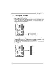
2.4 CONNECTORS AND SLOTS TA790GX3 A2+ FDD1: Floppy Disk Connector The motherboard provides a standard floppy disk connector that provides PIO Mode 0~4, Bus Master, and Ultra DMA 33/66/100/133 functionality. The IDE connector can connect a master and a slave drive, so you can connect up to two drives. 40 39 2 1 11 This connector supports the provided floppy drive ribbon cables. 2 34 1 33 IDE1: IDE/ATAPI Connector The motherboard has a 32-bit Enhanced IDE Controller that supports 360K, 720K, 1.2M, 1.44M and 2.88M floppy disk types.
2.4 CONNECTORS AND SLOTS TA790GX3 A2+ FDD1: Floppy Disk Connector The motherboard provides a standard floppy disk connector that provides PIO Mode 0~4, Bus Master, and Ultra DMA 33/66/100/133 functionality. The IDE connector can connect a master and a slave drive, so you can connect up to two drives. 40 39 2 1 11 This connector supports the provided floppy drive ribbon cables. 2 34 1 33 IDE1: IDE/ATAPI Connector The motherboard has a 32-bit Enhanced IDE Controller that supports 360K, 720K, 1.2M, 1.44M and 2.88M floppy disk types.
Setup Manual
Page 16
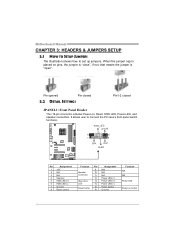
It allows user to set up jumpers. Motherboard Manual CHAPTER 3: HEADERS & JUMPERS SETUP 3.1 HOW TO SETUP JUMPERS The illustration shows how to connect the PC case's front panel switch functions. Pin opened Pin closed 3.2 DETAIL SETTINGS Pin1-2 closed JPANEL1: Front Panel Header This 16-pin connector includes Power-on button 14 PWR_LE D On/Off ++- 9 16 1 +- 8 SPK RST HLED Pin Assignment 1 +5V 2 N/A 3 N/A 4 Speaker 5 HDD LED (+) 6 HDD LED (-) 7 Ground 8 Reset control Function Pin 9 Speaker 10 Connector 11 12 Hard drive 13 LED 14 Reset button 15 16 ...
It allows user to set up jumpers. Motherboard Manual CHAPTER 3: HEADERS & JUMPERS SETUP 3.1 HOW TO SETUP JUMPERS The illustration shows how to connect the PC case's front panel switch functions. Pin opened Pin closed 3.2 DETAIL SETTINGS Pin1-2 closed JPANEL1: Front Panel Header This 16-pin connector includes Power-on button 14 PWR_LE D On/Off ++- 9 16 1 +- 8 SPK RST HLED Pin Assignment 1 +5V 2 N/A 3 N/A 4 Speaker 5 HDD LED (+) 6 HDD LED (-) 7 Ground 8 Reset control Function Pin 9 Speaker 10 Connector 11 12 Hard drive 13 LED 14 Reset button 15 16 ...
Setup Manual
Page 24
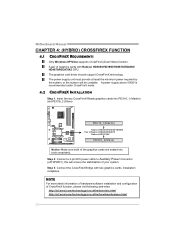
...://ati.amd.com/technology/crossfire/howitworksdemo.html 22 Motherboard Manual CHAPTER 4: (HYBRID) CROSSFIREX FUNCTION 4.1 CROSSFIREX REQUIREMENTS Only Windows XP/Vista supports CrossFireX (Dual Video) function. Installation completes. A pair of your system. The power supply unit must provide at least the minimum power required by the system, or the system will ensure the stabilization of graphics cards with two graphics cards. The graphics card driver should support CrossFireX technology. Step 2: Connect a 4-pin ATX power cable to Auxiliary Power Connector...
...://ati.amd.com/technology/crossfire/howitworksdemo.html 22 Motherboard Manual CHAPTER 4: (HYBRID) CROSSFIREX FUNCTION 4.1 CROSSFIREX REQUIREMENTS Only Windows XP/Vista supports CrossFireX (Dual Video) function. Installation completes. A pair of your system. The power supply unit must provide at least the minimum power required by the system, or the system will ensure the stabilization of graphics cards with two graphics cards. The graphics card driver should support CrossFireX technology. Step 2: Connect a 4-pin ATX power cable to Auxiliary Power Connector...
Setup Manual
Page 25
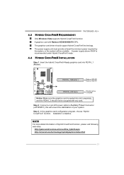
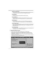
Step 3: In the graphics card configuration program, choose "Hybrid CrossFireX" function. A power supply above 450W is seated into PEX16_1 (Master). Step 2: Connect a 4-pin ATX power cable to Auxiliary Power Connector (JATXPWR1), this will be occupied with Radeon HD3450/HD3470 GPU. TA790GX3 A2+ 4.3 HYBRID CROSSFIREX REQUIREMENTS Only Windows Vista supports Hybrid CrossFireX function. A graphics card with any card. The power supply unit must provide at least the minimum power required by the system, or...
Step 3: In the graphics card configuration program, choose "Hybrid CrossFireX" function. A power supply above 450W is seated into PEX16_1 (Master). Step 2: Connect a 4-pin ATX power cable to Auxiliary Power Connector (JATXPWR1), this will be occupied with Radeon HD3450/HD3470 GPU. TA790GX3 A2+ 4.3 HYBRID CROSSFIREX REQUIREMENTS Only Windows Vista supports Hybrid CrossFireX function. A graphics card with any card. The power supply unit must provide at least the minimum power required by the system, or...

Setup Manual
Page 31
... Automate OverClock System =========== Auto OverClock System [V6-Tech Engine] Manual OverClock System CPU Frequency [200] > CPU FID/VID Control > Voltage Configuration > DRAM Timing Configuration > Hyper Transport Configuration > Memory Configuration > EC Configuration GFX Engine Clock Override [Disabled] Integrated Memory Test [Disabled] Options Normal Automate OverClock Manual OverClock Select Screen Select Item +- A. The BIOS information described below sections may be different from USB Flash Drive or FDD Self Recovery System (S.R.S) Smart Fan Function CMOS Reloading...
... Automate OverClock System =========== Auto OverClock System [V6-Tech Engine] Manual OverClock System CPU Frequency [200] > CPU FID/VID Control > Voltage Configuration > DRAM Timing Configuration > Hyper Transport Configuration > Memory Configuration > EC Configuration GFX Engine Clock Override [Disabled] Integrated Memory Test [Disabled] Options Normal Automate OverClock Manual OverClock Select Screen Select Item +- A. The BIOS information described below sections may be different from USB Flash Drive or FDD Self Recovery System (S.R.S) Smart Fan Function CMOS Reloading...
Setup Manual
Page 35
...sections may cause system to test memory compatibilities, and no extra devices or software are needed. OverClock Navigator [Normal] =========== Automate OverClock System =========== Auto OverClock System [V6-Tech Engine] Manual OverClock System CPU Frequency [200] > CPU FID/VID Control > Voltage Configuration > DRAM Timing Configuration > Hyper Transport Configuration > Memory Configuration > EC Configuration GFX Engine Clock Override [Disabled] Integrated Memory Test [Disabled] Options Enabled Disabled Select Screen Select Item +- Change Option F1 General Help F10 Save...
...sections may cause system to test memory compatibilities, and no extra devices or software are needed. OverClock Navigator [Normal] =========== Automate OverClock System =========== Auto OverClock System [V6-Tech Engine] Manual OverClock System CPU Frequency [200] > CPU FID/VID Control > Voltage Configuration > DRAM Timing Configuration > Hyper Transport Configuration > Memory Configuration > EC Configuration GFX Engine Clock Override [Disabled] Integrated Memory Test [Disabled] Options Enabled Disabled Select Screen Select Item +- Change Option F1 General Help F10 Save...
Setup Manual
Page 38
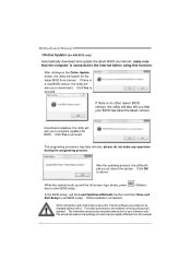
... On(℃) The CPU/System fan starts to work when CPU/System temperature arrives to reload any saved CMOS setting for customizing system configurations. Main Advanced PCIPnP Exit Options Save Changes and Exit Discard Changes and Exit Discard Changes Load Optimal Defaults CMOS Backup Function Security Settings > Security BIOS SETUP UTILITY Boot Chipset T-Series Exit CMOS Backup Func CMOS Data Reload CMOS Data Save Select Screen Select Item EnterGo to save different CMOS settings into BIOS-ROM. Motherboard Manual Smart Fan Calibration Choose this set value. The...
... On(℃) The CPU/System fan starts to work when CPU/System temperature arrives to reload any saved CMOS setting for customizing system configurations. Main Advanced PCIPnP Exit Options Save Changes and Exit Discard Changes and Exit Discard Changes Load Optimal Defaults CMOS Backup Function Security Settings > Security BIOS SETUP UTILITY Boot Chipset T-Series Exit CMOS Backup Func CMOS Data Reload CMOS Data Save Select Screen Select Item EnterGo to save different CMOS settings into BIOS-ROM. Motherboard Manual Smart Fan Calibration Choose this set value. The...
Setup Manual
Page 48
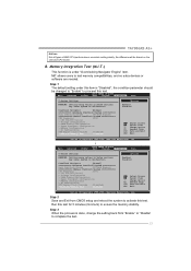
... screen logo shows, press key to reboot the system. After clicking on board may take minutes, please do not make sure that your reference only. After the updating process, the utility will ask you to enter BIOS setup. In the BIOS setup, use the Load Optimized Defaults function and then Save and Exit Setup to download it. The information and pictures described above about the T-Series software...
... screen logo shows, press key to reboot the system. After clicking on board may take minutes, please do not make sure that your reference only. After the updating process, the utility will ask you to enter BIOS setup. In the BIOS setup, use the Load Optimized Defaults function and then Save and Exit Setup to download it. The information and pictures described above about the T-Series software...
Setup Manual
Page 51
... are used for recovery 4 Flash Programming successful 5 File read error 7 No Flash EPROM detected 10 Flash Erase error 11 Flash Program error 12 "AMIBOOT.ROM" file size error 13 BIOS ROM image mismatch (file layout does not match image present in flash device) POST BIOS Beep Codes Number of Beeps Description 1 Memory refresh timer error 3 Base memory read/write test error 6 Keyboard controller BAT command failed 7 General exception error (processor exception interrupt error) 8 Display memory error (system video adapter) Troubleshooting POST BIOS Beep Codes Number...
... are used for recovery 4 Flash Programming successful 5 File read error 7 No Flash EPROM detected 10 Flash Erase error 11 Flash Program error 12 "AMIBOOT.ROM" file size error 13 BIOS ROM image mismatch (file layout does not match image present in flash device) POST BIOS Beep Codes Number of Beeps Description 1 Memory refresh timer error 3 Base memory read/write test error 6 Keyboard controller BAT command failed 7 General exception error (processor exception interrupt error) 8 Display memory error (system video adapter) Troubleshooting POST BIOS Beep Codes Number...
Bios Manual
Page 2
... and T oshiba. 1 ACPI Support AMI ACPI BIOS support Version 1.0/2.0 of the Advanced Power Man agement (APM) speci fication. TA790GX3 A2+ BIOS Manual BIOS Setup Introduction T he purpose of this manual is turned off. T his AMI BIOS supports Version 1.1&1.2 of Advanced Configuration and Power interface specifi cation (ACPI). It provides ASL code for pow er manag ement and device con figuration capabilities as keyboard, mouse, serial ports and disk drives. EPA Green PC Support T his AMI BIOS supports the Plug and Play Version 1.0A specification.
... and T oshiba. 1 ACPI Support AMI ACPI BIOS support Version 1.0/2.0 of the Advanced Power Man agement (APM) speci fication. TA790GX3 A2+ BIOS Manual BIOS Setup Introduction T he purpose of this manual is turned off. T his AMI BIOS supports Version 1.1&1.2 of Advanced Configuration and Power interface specifi cation (ACPI). It provides ASL code for pow er manag ement and device con figuration capabilities as keyboard, mouse, serial ports and disk drives. EPA Green PC Support T his AMI BIOS supports the Plug and Play Version 1.0A specification.
Bios Manual
Page 6
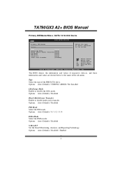
... Set the Smart Monitoring, Analysis, and Reporting T echnology. SATA 1/2/3/4/5/6 Dev ice Main BIOS SETUP UTILITY Primary IDE Master Device : Type [Auto] LBA/Large Mode [Auto] Block (Multi-Sector Transfer)[Auto] PIO Mode [Auto] DMA Mode [Auto] S.M.A.R.T [Auto] 32Bit Data Transfer [Enabled] Select the type of device connected to the name of the IDE/SAT A drive. TA790GX3 A2+ BIOS Manual Primary IDE Master/Slav e ; Options: Auto (Default) / CDROM / ARMD / Not Installed LBA/Large Mode Enable or disable the LBA mode. Options: Auto (Default) / Disabled PIO Mode...
... Set the Smart Monitoring, Analysis, and Reporting T echnology. SATA 1/2/3/4/5/6 Dev ice Main BIOS SETUP UTILITY Primary IDE Master Device : Type [Auto] LBA/Large Mode [Auto] Block (Multi-Sector Transfer)[Auto] PIO Mode [Auto] DMA Mode [Auto] S.M.A.R.T [Auto] 32Bit Data Transfer [Enabled] Select the type of device connected to the name of the IDE/SAT A drive. TA790GX3 A2+ BIOS Manual Primary IDE Master/Slav e ; Options: Auto (Default) / CDROM / ARMD / Not Installed LBA/Large Mode Enable or disable the LBA mode. Options: Auto (Default) / Disabled PIO Mode...
Bios Manual
Page 9
... operating system at boot time and uses the information to enable or disable the Cool & Quiet power saving technology. Options: Enabled (Default) / Disabled 8 If you to better allocate memory and schedule software threads for maximum perform ance. Options: Enabled (Default) / Disabled ACPI SRAT Table T he operating system scans the ACPI SRAT at boot up, or not. TA790GX3 A2+ BIOS Manual Secure Virtual Machine Mode Virtualization T echnology can virtually separate your system has a floppy disk controller (FDC) installed on AC Power Loss [Ena...
... operating system at boot time and uses the information to enable or disable the Cool & Quiet power saving technology. Options: Enabled (Default) / Disabled 8 If you to better allocate memory and schedule software threads for maximum perform ance. Options: Enabled (Default) / Disabled ACPI SRAT Table T he operating system scans the ACPI SRAT at boot up, or not. TA790GX3 A2+ BIOS Manual Secure Virtual Machine Mode Virtualization T echnology can virtually separate your system has a floppy disk controller (FDC) installed on AC Power Loss [Ena...
Bios Manual
Page 12
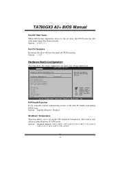
Options: Enabled (Default) / Disabled Shutdow n Temperature T his item shows the system temperature, fan speed, and voltage information. This item is only effective under Smart Fan Function mode. TA790GX3 A2+ BIOS Manual Fan Ctrl Start Value When CPU/System temperature arriv es to set value, the CPU/System fan will work under Windows 98 ACPI mode. Options: 1~127 Hardware Health Configuration T his item allows you computer contains a monitoring system, it will raise the speed of CPU/System fan. Advan ced BIOS SETU P U TILITY Hardware Healt h Configuration H/W Health...
Options: Enabled (Default) / Disabled Shutdow n Temperature T his item shows the system temperature, fan speed, and voltage information. This item is only effective under Smart Fan Function mode. TA790GX3 A2+ BIOS Manual Fan Ctrl Start Value When CPU/System temperature arriv es to set value, the CPU/System fan will work under Windows 98 ACPI mode. Options: 1~127 Hardware Health Configuration T his item allows you computer contains a monitoring system, it will raise the speed of CPU/System fan. Advan ced BIOS SETU P U TILITY Hardware Healt h Configuration H/W Health...
Bios Manual
Page 13
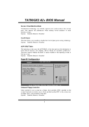
... the version of ACPI. Options: S1 (POS) (Default) Power on Suspend S3 (ST R) Suspend to RAM S1 & S3 POS+STR ACPI Version Features T he item allows you to select the suspend type under the ACPI operating system. Options: Enabled (Default) / Disabled 12 TA790GX3 A2+ BIOS Manual Power Configuration Advan ced BIOS SETU P U TILITY ACPI Settings Suspend mode ACPI Version F eatures ACPI APIC supp ort AMI OEMB table Headless mode RTC Resume RTC Alarm Date (Days) RTC Alarm Time USB...
... the version of ACPI. Options: S1 (POS) (Default) Power on Suspend S3 (ST R) Suspend to RAM S1 & S3 POS+STR ACPI Version Features T he item allows you to select the suspend type under the ACPI operating system. Options: Enabled (Default) / Disabled 12 TA790GX3 A2+ BIOS Manual Power Configuration Advan ced BIOS SETU P U TILITY ACPI Settings Suspend mode ACPI Version F eatures ACPI APIC supp ort AMI OEMB table Headless mode RTC Resume RTC Alarm Date (Days) RTC Alarm Time USB...
Bios Manual
Page 26
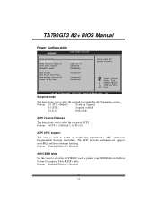
... Slots Power Limit, W Options: 25 (Default) / 0-255 25 Options: Auto (Default) / Disabled FB Location T his item allows you to control the Surround View Function. Options: Enabled (Default) / Disabled PCI Express Configuration BIOS SETU P U TILITY Chipset PCI Express Co nfiguration GFX Dual Slot Configuration [Dis abled] GPP Slots Powe r Limit, W [25 ] > Port #02 Fea tures > Port #04 Fea tures > Port #05 Fea tures > Port #06 Fea tures > Port #07 Fea tures > Port #09 Fea tures > Port #10 Fea tures > NB-SB Port F eatures Options Auto Enabled Disabled S elect Screen...
... Slots Power Limit, W Options: 25 (Default) / 0-255 25 Options: Auto (Default) / Disabled FB Location T his item allows you to control the Surround View Function. Options: Enabled (Default) / Disabled PCI Express Configuration BIOS SETU P U TILITY Chipset PCI Express Co nfiguration GFX Dual Slot Configuration [Dis abled] GPP Slots Powe r Limit, W [25 ] > Port #02 Fea tures > Port #04 Fea tures > Port #05 Fea tures > Port #06 Fea tures > Port #07 Fea tures > Port #09 Fea tures > Port #10 Fea tures > NB-SB Port F eatures Options Auto Enabled Disabled S elect Screen...
Bios Manual
Page 30
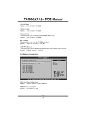
... MAC ID. MAC ID Information T his item allows you to enable or disable the Onboard LAN Boot ROM. C hange Option F1 G eneral Help F10 S ave and Exit ESC E xit vxx .xx (C)Copyright 1985-200x, American Me gatrends, Inc. TA790GX3 A2+ BIOS Manual OnBoard Peripherals Configuration BIOS SETU P U TILITY Chipset MAC ID Informa tion Realtek PCIE N IC Realtek Optio n ROM [Ena ble] [Dis abled] Enable/Disable Onboard RTL8111C PCIE Network Controller S elect Screen S elect Item +-
... MAC ID. MAC ID Information T his item allows you to enable or disable the Onboard LAN Boot ROM. C hange Option F1 G eneral Help F10 S ave and Exit ESC E xit vxx .xx (C)Copyright 1985-200x, American Me gatrends, Inc. TA790GX3 A2+ BIOS Manual OnBoard Peripherals Configuration BIOS SETU P U TILITY Chipset MAC ID Informa tion Realtek PCIE N IC Realtek Optio n ROM [Ena ble] [Dis abled] Enable/Disable Onboard RTL8111C PCIE Network Controller S elect Screen S elect Item +-
Bios Manual
Page 44
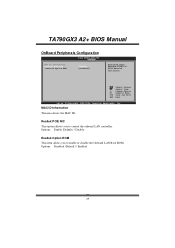
TA790GX3 A2+ BIOS Manual CMOS Backup Function It allows users to save an ideal overclock setting during overclock operation. S elect Screen S elect Item EnterC hange F1 G eneral Help F10 S ave and Exit ESC E xit vxx .xx (C)Copyright 1985-200x, American Me gatrends, Inc. 43 Main Advan ced BIOS SETU P U TILITY PCIPnP Boot Chipset T-Series Exit Exit Options Save Changes a nd Exit Discard Change s and Exit Discard Change s Load Optimal D efaults CMOS Backup...
TA790GX3 A2+ BIOS Manual CMOS Backup Function It allows users to save an ideal overclock setting during overclock operation. S elect Screen S elect Item EnterC hange F1 G eneral Help F10 S ave and Exit ESC E xit vxx .xx (C)Copyright 1985-200x, American Me gatrends, Inc. 43 Main Advan ced BIOS SETU P U TILITY PCIPnP Boot Chipset T-Series Exit Exit Options Save Changes a nd Exit Discard Change s and Exit Discard Change s Load Optimal D efaults CMOS Backup...


