

MANUAL
Page 1
... found to comply with the limits of this user's manual is not allowed without notice and we will not occur in a particular installation. These limits are trademarks of the FCC Rules. TF7050-M2/TF7025-M2 Setup Manual FCC Information and Copyright This equipment has been tested and... found in this user's manual. Further the vendor reserves the right to revise this publication and to make changes to...
... found to comply with the limits of this user's manual is not allowed without notice and we will not occur in a particular installation. These limits are trademarks of the FCC Rules. TF7050-M2/TF7025-M2 Setup Manual FCC Information and Copyright This equipment has been tested and... found in this user's manual. Further the vendor reserves the right to revise this publication and to make changes to...
MANUAL
Page 3
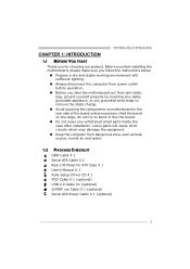
... dry and stable working environment with sufficient lighting. „ Always disconnect the computer from power outlet before operation. „ Before you for ATX Case X 1 User's Manual X 1 Fully Setup Driver CD X 1 FDD Cable X 1 (optional) USB 2.0 Cable X1 (optional) S/PDIF out Cable X 1 (optional) Serial ATA Power ... remove the static charge. „ Avoid touching the components on motherboard or the rear side of the board unless necessary. TF7050-M2/TF7025-M2 CHAPTER 1: INTRODUCTION 1.1 BEFORE YOU START Thank you take the motherboard out from dangerous area, such as heat source, humid air...
... dry and stable working environment with sufficient lighting. „ Always disconnect the computer from power outlet before operation. „ Before you for ATX Case X 1 User's Manual X 1 Fully Setup Driver CD X 1 FDD Cable X 1 (optional) USB 2.0 Cable X1 (optional) S/PDIF out Cable X 1 (optional) Serial ATA Power ... remove the static charge. „ Avoid touching the components on motherboard or the rear side of the board unless necessary. TF7050-M2/TF7025-M2 CHAPTER 1: INTRODUCTION 1.1 BEFORE YOU START Thank you take the motherboard out from dangerous area, such as heat source, humid air...

MANUAL
Page 4
Motherboard Manual 1.3 MOTHERBOARD FEATURES TF7050-M2 TF7025-M2 Socket AM2 Socket AM2 AMD Athlon 64 / Athlon 64 FX / Athlon 64 x2 / AMD Athlon 64 / Athlon 64 FX / Athlon 64 x2 / Sempron processors Sempron ...
Motherboard Manual 1.3 MOTHERBOARD FEATURES TF7050-M2 TF7025-M2 Socket AM2 Socket AM2 AMD Athlon 64 / Athlon 64 FX / Athlon 64 x2 / AMD Athlon 64 / Athlon 64 FX / Athlon 64 x2 / Sempron processors Sempron ...
MANUAL
Page 6
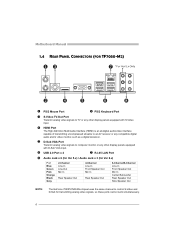
Motherboard Manual 1.4 REAR PANEL CONNECTORS (FOR TF7050-M2) X PS/2 Mouse Port Y PS/2 Keyboard Port Z S-Video TV-Out Port Transmit analog video signals to TV or any other display panels equipped with S-Video input. [ ...
Motherboard Manual 1.4 REAR PANEL CONNECTORS (FOR TF7050-M2) X PS/2 Mouse Port Y PS/2 Keyboard Port Z S-Video TV-Out Port Transmit analog video signals to TV or any other display panels equipped with S-Video input. [ ...
MANUAL
Page 8
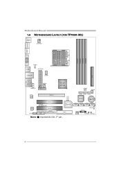
JUSB2 JUSB3 JUSB4 BIOS BAT1 SATA1 SATA2 SATA3 SATA4 JCMOS1 JPANEL1 JSFAN1 PWRSW1 RSTSW1 8 Motherboard Manual 1.6 MOTHERBOARD LAYOUT (FOR TF7050-M2) JKBMS1 JATXPWR2 JTVOUT1 JHDMI DIMMA1 DIMMB1 DIMMA2 DIMMB2 Socket A M2 VGA JUSB1 JUSBV1 JATXPWR1 IDE1 JUSBLAN1 JCFAN1 JAUDIO2 (for Ver 5.x) JAUDIO1 (for Ver 6.x) JAUDIOF1 JNFAN1 PEX1_1 GeForce 7050PV/ NF630a JUSBV2 JSFAN2 LED_D1 LED_D2 PEX16_1 LAN PCI1 JCOM1 Super I/O Codec JCDIN1 PCI2 JSPDIF_IN1 JSPDIF_OUT1 JPRNT1 FDD1 Note: ■ represents the 1st pin.
JUSB2 JUSB3 JUSB4 BIOS BAT1 SATA1 SATA2 SATA3 SATA4 JCMOS1 JPANEL1 JSFAN1 PWRSW1 RSTSW1 8 Motherboard Manual 1.6 MOTHERBOARD LAYOUT (FOR TF7050-M2) JKBMS1 JATXPWR2 JTVOUT1 JHDMI DIMMA1 DIMMB1 DIMMA2 DIMMB2 Socket A M2 VGA JUSB1 JUSBV1 JATXPWR1 IDE1 JUSBLAN1 JCFAN1 JAUDIO2 (for Ver 5.x) JAUDIO1 (for Ver 6.x) JAUDIOF1 JNFAN1 PEX1_1 GeForce 7050PV/ NF630a JUSBV2 JSFAN2 LED_D1 LED_D2 PEX16_1 LAN PCI1 JCOM1 Super I/O Codec JCDIN1 PCI2 JSPDIF_IN1 JSPDIF_OUT1 JPRNT1 FDD1 Note: ■ represents the 1st pin.
MANUAL
Page 10
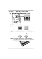
Motherboard Manual CHAPTER 2: HARDWARE INSTALLATION 2.1 INSTALLING CENTRAL PROCESSING UNIT (CPU) Step 1: Remove the socket protection cap. The CPU will fit only in the correct orientation. 10 Step 2: Pull the lever toward direction A from the socket and then raise the lever up to a 90-degree angle. Step 3: Look for the white triangle on socket, and the gold triangle on CPU should point towards this white triangle.
Motherboard Manual CHAPTER 2: HARDWARE INSTALLATION 2.1 INSTALLING CENTRAL PROCESSING UNIT (CPU) Step 1: Remove the socket protection cap. The CPU will fit only in the correct orientation. 10 Step 2: Pull the lever toward direction A from the socket and then raise the lever up to a 90-degree angle. Step 3: Look for the white triangle on socket, and the gold triangle on CPU should point towards this white triangle.
MANUAL
Page 12
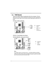
... is the positive and should be connected to pin#2, and the black wire is Ground and should be different according to the fan manufacturer. Motherboard Manual 2.2 FAN HEADERS These fan headers support cooling-fans built in the computer. Connect the fan cable to the connector while matching the black wire to...
... is the positive and should be connected to pin#2, and the black wire is Ground and should be different according to the fan manufacturer. Motherboard Manual 2.2 FAN HEADERS These fan headers support cooling-fans built in the computer. Connect the fan cable to the connector while matching the black wire to...
MANUAL
Page 14
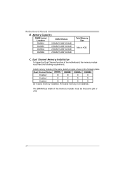
Motherboard Manual B. C. Dual Channel Memory installation To trigger the Dual Channel function of the motherboard, the memory module must meet the following table. Memory Capacity DIMM Socket ...
Motherboard Manual B. C. Dual Channel Memory installation To trigger the Dual Channel function of the motherboard, the memory module must meet the following table. Memory Capacity DIMM Socket ...
MANUAL
Page 16
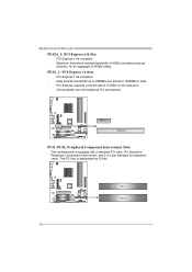
PCI-Express supports a raw bit-rate of 8GB/s totally. Maximum theoretical realized bandwidth of 4GB/s simultaneously per direction; 500MB/s in total. - Motherboard Manual PEX16_1: PCI-Express x16 Slot - Data transfer bandwidth up to 250MB/s per direction, for expansion cards. PEX1_1 PEX16_1 PCI1~PCI2: Peripheral Component Interconnect Slots This ...
PCI-Express supports a raw bit-rate of 8GB/s totally. Maximum theoretical realized bandwidth of 4GB/s simultaneously per direction; 500MB/s in total. - Motherboard Manual PEX16_1: PCI-Express x16 Slot - Data transfer bandwidth up to 250MB/s per direction, for expansion cards. PEX1_1 PEX16_1 PCI1~PCI2: Peripheral Component Interconnect Slots This ...
MANUAL
Page 18
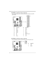
Motherboard Manual JATXPWR1: ATX Power Source Connector This connector allows user to connect 24-pin power connector on the ATX power supply. 12 24 Pin Assignment 13 +3....
Motherboard Manual JATXPWR1: ATX Power Source Connector This connector allows user to connect 24-pin power connector on the ATX power supply. 12 24 Pin Assignment 13 +3....
MANUAL
Page 20
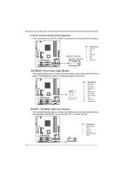
... SATA4 6 7 RX+ Ground 741 JAUDIOF1: Front Panel Audio Header This header allows user to connect the front audio output cable with 4 channels SATA interface. Motherboard Manual SATA1~SATA4: Serial ATA Connectors The motherboard has a PCI to SATA Controller with the PC front panel.
... SATA4 6 7 RX+ Ground 741 JAUDIOF1: Front Panel Audio Header This header allows user to connect the front audio output cable with 4 channels SATA interface. Motherboard Manual SATA1~SATA4: Serial ATA Connectors The motherboard has a PCI to SATA Controller with the PC front panel.
MANUAL
Page 22
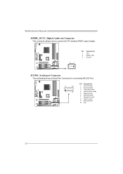
Motherboard Manual JSPDIF_OUT1: Digital Audio-out Connector This connector allows user to connect the PCI bracket SPDIF output header. 3 1 Pin Assignment 1 +5V 2 SPDIF_OUT 3 Ground JCOM1: Serial port Connector The motherboard has a Serial Port Connector for connecting RS-232 Port. 2 10 1 9 Pin Assignment 1 Carrier detect 2 Received data 3 Transmitted data 4 Data terminal ready 5 Signal ground 6 Data set ready 7 Request to send 8 Clear to send 9 Ring indicator 10 Key 22
Motherboard Manual JSPDIF_OUT1: Digital Audio-out Connector This connector allows user to connect the PCI bracket SPDIF output header. 3 1 Pin Assignment 1 +5V 2 SPDIF_OUT 3 Ground JCOM1: Serial port Connector The motherboard has a Serial Port Connector for connecting RS-232 Port. 2 10 1 9 Pin Assignment 1 Carrier detect 2 Received data 3 Transmitted data 4 Data terminal ready 5 Signal ground 6 Data set ready 7 Request to send 8 Clear to send 9 Ring indicator 10 Key 22
MANUAL
Page 24
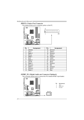
Motherboard Manual JPRNT1: Printer Port Connector This header allows you to connector printer on the PC. 2 1 25 Pin Assignment 1 -Strobe 2 -ALF 3 Data 0 4 -Error 5 Data 1 6 -Init 7 Data 2 8 -Scltin 9 Data 3 10 Ground 11 Data 4 12 Ground 13 Data 5 Pin Assignment 14 Ground 15 Data 6 16 Ground 17 Data 7 18 Ground 19 -ACK 20 Ground 21 Busy 22 Ground 23 PE 24 Ground 25 SCLT 26 Key JSPDIF_IN1: Digital Audio-out Connector (Optional) This connector allows user to connect the PCI bracket SPDIF input header. 3 1 Pin Assignment 1 +5V 2 SPDIF_IN 3 Ground 24
Motherboard Manual JPRNT1: Printer Port Connector This header allows you to connector printer on the PC. 2 1 25 Pin Assignment 1 -Strobe 2 -ALF 3 Data 0 4 -Error 5 Data 1 6 -Init 7 Data 2 8 -Scltin 9 Data 3 10 Ground 11 Data 4 12 Ground 13 Data 5 Pin Assignment 14 Ground 15 Data 6 16 Ground 17 Data 7 18 Ground 19 -ACK 20 Ground 21 Busy 22 Ground 23 PE 24 Ground 25 SCLT 26 Key JSPDIF_IN1: Digital Audio-out Connector (Optional) This connector allows user to connect the PCI bracket SPDIF input header. 3 1 Pin Assignment 1 +5V 2 SPDIF_IN 3 Ground 24
MANUAL
Page 26
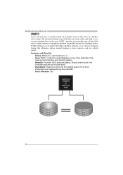
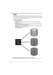
... and Benefits Drives: Minimum 2, and maximum is 2. Uses: RAID 1 is ideal for small databases or any other application that eliminates tedious manual backups to the other drive. Drawbacks: Requires 2 drives for high-availability solutions, or as a form of one drive fail, the controller switches to ...is impaired during drive rebuilds. Fault Tolerance: Yes. RAID 1 provides a hot-standby copy of a hardware failure. Should one drive. Motherboard Manual RAID 1: Every read and write is actually carried out in parallel across 2 disk drives in the array.
... and Benefits Drives: Minimum 2, and maximum is 2. Uses: RAID 1 is ideal for small databases or any other application that eliminates tedious manual backups to the other drive. Drawbacks: Requires 2 drives for high-availability solutions, or as a form of one drive fail, the controller switches to ...is impaired during drive rebuilds. Fault Tolerance: Yes. RAID 1 provides a hot-standby copy of a hardware failure. Should one drive. Motherboard Manual RAID 1: Every read and write is actually carried out in parallel across 2 disk drives in the array.
MANUAL
Page 28
... or GeForce 7025 Disk 2 DATA 2 PARITY DATA 5 DATA 8 PARITY DATA 11 Disk 3 PARITY DATA 4 DATA 6 PARITY DATA 10 DATA 12 ※ For more drives. Motherboard Manual RAID 5: RAID 5 stripes both data and parity information across all the drives in the array. Features and Benefits Drives: Minimum 3. Uses: RAID 5 is...
... or GeForce 7025 Disk 2 DATA 2 PARITY DATA 5 DATA 8 PARITY DATA 11 Disk 3 PARITY DATA 4 DATA 6 PARITY DATA 10 DATA 12 ※ For more drives. Motherboard Manual RAID 5: RAID 5 stripes both data and parity information across all the drives in the array. Features and Benefits Drives: Minimum 3. Uses: RAID 5 is...
MANUAL
Page 30
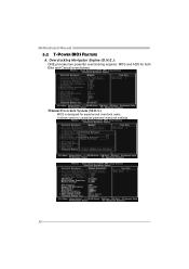
It allows users to customize personal overclock settings. 30 Motherboard Manual 5.2 T-POWER BIOS FEATURE A. Manual Overclock System (M.O.S.) MOS is designed for both Elite and Casual overclockers. Overclocking Navigator Engine (O.N.E.): ONE provides two powerful overclocking engines: MOS and AOS for experienced overclock users.
It allows users to customize personal overclock settings. 30 Motherboard Manual 5.2 T-POWER BIOS FEATURE A. Manual Overclock System (M.O.S.) MOS is designed for both Elite and Casual overclockers. Overclocking Navigator Engine (O.N.E.): ONE provides two powerful overclocking engines: MOS and AOS for experienced overclock users.

MANUAL
Page 32
provides 3 ideal overclock configurations that are able to increase the system performance, named A.O.S. Motherboard Manual Automatic Overclock System (A.O.S.) For beginners in overclock field, BET had developed an easy, fast, and powerful feature to raise the system performance in a single step. Based on many tests and experiments, A.O.S. V8 Tech Engine: This setting will raise about 15%~25% of whole system performance. V6 Tech Engine: This setting will raise about 10%~15% of whole system performance. 32
provides 3 ideal overclock configurations that are able to increase the system performance, named A.O.S. Motherboard Manual Automatic Overclock System (A.O.S.) For beginners in overclock field, BET had developed an easy, fast, and powerful feature to raise the system performance in a single step. Based on many tests and experiments, A.O.S. V8 Tech Engine: This setting will raise about 15%~25% of whole system performance. V6 Tech Engine: This setting will raise about 10%~15% of whole system performance. 32
MANUAL
Page 34
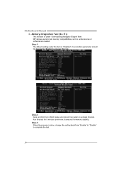
..." to proceed this test. ↓ Step 2: Save and Exit from "Enable" to "Disable" to complete the test. 34 Step 3: When the process is "Disabled"; Motherboard Manual C. Memory Integration Test (M.I.T.): This function is under this item is done, change the setting back from CMOS setup and reboot the system to activate this...
..." to proceed this test. ↓ Step 2: Save and Exit from "Enable" to "Disable" to complete the test. 34 Step 3: When the process is "Disabled"; Motherboard Manual C. Memory Integration Test (M.I.T.): This function is under this item is done, change the setting back from CMOS setup and reboot the system to activate this...
MANUAL
Page 36
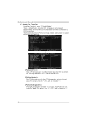
... the system temperature at a safe level. ↓ CPU Fan Off : If the CPU temperature is from 0℃~127℃, with an interval of 1℃. Motherboard Manual F. This function will work when CPU temperature arrives to work under "PC Health Status".
... the system temperature at a safe level. ↓ CPU Fan Off : If the CPU temperature is from 0℃~127℃, with an interval of 1℃. Motherboard Manual F. This function will work when CPU temperature arrives to work under "PC Health Status".
MANUAL
Page 38
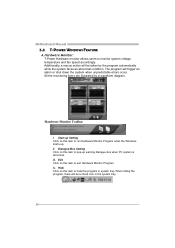
... this program in the system tray. 38 All the monitoring items are illustrated by the program automatically while the system faces an abnormal condition. Motherboard Manual 5.3 T-POWER WINDOWS FEATURE A.Hardware Monitor: T-Power Hardware monitor allows users to run Hardware Monitor Program when the Windows starts-up warning dialogue-box when PC...
... this program in the system tray. 38 All the monitoring items are illustrated by the program automatically while the system faces an abnormal condition. Motherboard Manual 5.3 T-POWER WINDOWS FEATURE A.Hardware Monitor: T-Power Hardware monitor allows users to run Hardware Monitor Program when the Windows starts-up warning dialogue-box when PC...

