

TForce4 U 775 user's manual
Page 1
... any implied warranties of merchantability or fitness for any mistakes found to comply with the instructions, may cause harmful interference to notify any party beforehand. Biostar T-Series TForce4 U 775 FCC Information and Copyright This equipment has been tested and found in this user's manual.
... any implied warranties of merchantability or fitness for any mistakes found to comply with the instructions, may cause harmful interference to notify any party beforehand. Biostar T-Series TForce4 U 775 FCC Information and Copyright This equipment has been tested and found in this user's manual.

TForce4 U 775 user's manual
Page 2
Biostar T-Series TForce4 U 775 PACKAGE CHECKLIST I /O Slots 4 B. About FAN Headers 3 2.2 SYSTEM MEMORY 4 A. Card and I CHAPTER 1: INTRODUCTION 1 1.1 MOTHERBOARD FEATURES 1 1.2 LAYOUT AND COMPONENTS 2 CHAPTER 2: HARDWARE INSTALLATIONS 3 2.1 CPU ASSEMBLY 3 A. CPU Overheated 14 4.3 ...
Biostar T-Series TForce4 U 775 PACKAGE CHECKLIST I /O Slots 4 B. About FAN Headers 3 2.2 SYSTEM MEMORY 4 A. Card and I CHAPTER 1: INTRODUCTION 1 1.1 MOTHERBOARD FEATURES 1 1.2 LAYOUT AND COMPONENTS 2 CHAPTER 2: HARDWARE INSTALLATIONS 3 2.1 CPU ASSEMBLY 3 A. CPU Overheated 14 4.3 ...
TForce4 U 775 user's manual
Page 3
... 64 Technology (Intel EM64T). South Bridge: nForce 430 / nForce 410. - AC'97 Audio Sound Codec Chip: ALC850, supports 8 channels audio output. Biostar T-Series TForce4 U 775 Chapter 1: Introduction 1.1 MOTHERBOARD FEATURES CPU Supports LGA 775. Supports Intel Pentium 4 processor and Celeron D. Supports Pentium EE Front Side Bus at the following frequency ranges: 533MT/s (133MHzCore Clock) ...
... 64 Technology (Intel EM64T). South Bridge: nForce 430 / nForce 410. - AC'97 Audio Sound Codec Chip: ALC850, supports 8 channels audio output. Biostar T-Series TForce4 U 775 Chapter 1: Introduction 1.1 MOTHERBOARD FEATURES CPU Supports LGA 775. Supports Intel Pentium 4 processor and Celeron D. Supports Pentium EE Front Side Bus at the following frequency ranges: 533MT/s (133MHzCore Clock) ...

TForce4 U 775 user's manual
Page 4
Biostar T-Series 1.2 LAYOUT AND COMPONENTS Super I/O LED_D1 LED_D2 JSPDIF_IN1 (optional) Codec JCDIN1 LAN JAUDIO1 JUSBLAN1 JUSB3 JFAUDIO1 JATXPWR1 TForce4 U 775 JPRNT1 JCOM1 JKBV1 JKBMS1 JATXPWR2 LGA775 CPU1 PCI-Ex16-1 PCI-Ex1_1 PCI-Ex1_2 PCI1 PCI2 PCI3 PCI4 JSPDIF_OUT1 JSFAN2 BIOS JUSB1 JUSB2 JPANEL1 nForce 430 / nForce 410 JCI1 SATA1 IR Heade r (Op ti onal ) SATA4 JCMOS1 BAT1 JSFAN1 SATA2 SATA3 Note: ■ represents the 1st pin. IDE2 IDE1 NForce 4 SPP Ultra JNBFAN1 JDDR2_OV>3V (optional) FDD1 2 DDR2_A1 DDR2_A2 DDR2_B1 DDR2_B2 JCFAN1 User's Manual
Biostar T-Series 1.2 LAYOUT AND COMPONENTS Super I/O LED_D1 LED_D2 JSPDIF_IN1 (optional) Codec JCDIN1 LAN JAUDIO1 JUSBLAN1 JUSB3 JFAUDIO1 JATXPWR1 TForce4 U 775 JPRNT1 JCOM1 JKBV1 JKBMS1 JATXPWR2 LGA775 CPU1 PCI-Ex16-1 PCI-Ex1_1 PCI-Ex1_2 PCI1 PCI2 PCI3 PCI4 JSPDIF_OUT1 JSFAN2 BIOS JUSB1 JUSB2 JPANEL1 nForce 430 / nForce 410 JCI1 SATA1 IR Heade r (Op ti onal ) SATA4 JCMOS1 BAT1 JSFAN1 SATA2 SATA3 Note: ■ represents the 1st pin. IDE2 IDE1 NForce 4 SPP Ultra JNBFAN1 JDDR2_OV>3V (optional) FDD1 2 DDR2_A1 DDR2_A2 DDR2_B1 DDR2_B2 JCFAN1 User's Manual

TForce4 U 775 user's manual
Page 5
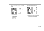
Step 2-2: TForce4 U 775 Step 3: Hold the CPU down firmly, and then lower the lever to locked position to a 90-degree angle. Step 2-1: 3 Step 4: Put the CPU Fan and ... triangular cut edge on socket, and the golden dot on CPU should be damaged. It supports 4 pin head connector. User's Manual This completes the installation. Biostar T-Series Chapter 2: Hardware Installations 2.1 CPU ASSEMBLY A. Central Processing Unit (CPU) Special Notice: Remove Pin Cap before installation, and make good preservation for the triangular cut edge...
Step 2-2: TForce4 U 775 Step 3: Hold the CPU down firmly, and then lower the lever to locked position to a 90-degree angle. Step 2-1: 3 Step 4: Put the CPU Fan and ... triangular cut edge on socket, and the golden dot on CPU should be damaged. It supports 4 pin head connector. User's Manual This completes the installation. Biostar T-Series Chapter 2: Hardware Installations 2.1 CPU ASSEMBLY A. Central Processing Unit (CPU) Special Notice: Remove Pin Cap before installation, and make good preservation for the triangular cut edge...

TForce4 U 775 user's manual
Page 6
... to IDE1. 39 IDE2 1 40 IDE1 2 User's Manual Align a DIMM on the slot such that supports 360K, 720K, 1.2M, 1.44M and 2.88M floppy disk types. Biostar T-Series 2.2 SYSTEM MEMORY DDR2_A1 DDR2_A2 DDR2_B1 DDR2_B2 TForce4 U 775 2.3 PERIPHERALS A. This connector supports the provided floppy drive ribbon cables. 34 33 A.
... to IDE1. 39 IDE2 1 40 IDE1 2 User's Manual Align a DIMM on the slot such that supports 360K, 720K, 1.2M, 1.44M and 2.88M floppy disk types. Biostar T-Series 2.2 SYSTEM MEMORY DDR2_A1 DDR2_A2 DDR2_B1 DDR2_B2 TForce4 U 775 2.3 PERIPHERALS A. This connector supports the provided floppy drive ribbon cables. 34 33 A.

TForce4 U 775 user's manual
Page 7
PCI Express 1.0a compliant. - PCI-Ex16-1 PCI-Ex1_1 PCI-Ex1_2 TForce4 U 775 B. Connectors and Headers: How to setup Jumpers The illustration shows how to set up to 250MB/s per direction. PCI Express 1.0a compliant. - Maximum bandwidth is ...-1/PCI-Ex1_1/PCI-Ex1_2 PCI-Ex16-1: - Maximum bandwidth is "open". When the jumper cap is placed on pins, the jumper is designated as 32 bits. Biostar T-Series Peripheral Component Interconnect Slots: PCI1~PCI4 This motherboard is a bus standard for expansion cards. PCI stands for Peripheral Component Interconnect, and it is equipped with...
PCI Express 1.0a compliant. - PCI-Ex16-1 PCI-Ex1_1 PCI-Ex1_2 TForce4 U 775 B. Connectors and Headers: How to setup Jumpers The illustration shows how to set up to 250MB/s per direction. PCI Express 1.0a compliant. - Maximum bandwidth is ...-1/PCI-Ex1_1/PCI-Ex1_2 PCI-Ex16-1: - Maximum bandwidth is "open". When the jumper cap is placed on pins, the jumper is designated as 32 bits. Biostar T-Series Peripheral Component Interconnect Slots: PCI1~PCI4 This motherboard is a bus standard for expansion cards. PCI stands for Peripheral Component Interconnect, and it is equipped with...

TForce4 U 775 user's manual
Page 8
TForce4 U 775 Front Panel Audio-out Header: JAUDIOF1 This connector will disable the output on back panel audio connectors. It will allow user to connect with +5V ...: JKBV1 Pin 1-2 Close: +5V for PS/2 keyboard and mouse. Pin 2-3 Close: PS/2 keyboard and mouse are powered with the front audio output headers on Pin 2-3. Biostar T-Series ATX Power Source Connector: JATXPWR2 By connecting JATXPWR2, it will provide +12V to support this function "Power-on system via keyboard and mouse," JKBV1 jumper...
TForce4 U 775 Front Panel Audio-out Header: JAUDIOF1 This connector will disable the output on back panel audio connectors. It will allow user to connect with +5V ...: JKBV1 Pin 1-2 Close: +5V for PS/2 keyboard and mouse. Pin 2-3 Close: PS/2 keyboard and mouse are powered with the front audio output headers on Pin 2-3. Biostar T-Series ATX Power Source Connector: JATXPWR2 By connecting JATXPWR2, it will provide +12V to support this function "Power-on system via keyboard and mouse," JKBV1 jumper...

TForce4 U 775 user's manual
Page 9
... 10 9 Pin Assignment 1 +5V (fused) 2 +5V (fused) 3 USB4 USB5 USB+ 6 USB+ 7 Ground 8 Ground 9 Key 10 NC TForce4 U 775 Digital Audio-out Connector: JSPDIF_OUT1 This connector allows users to connect the PCI bracket SPDIF input header. Biostar T-Series CD-ROM Audio-in Connector: JCDIN1 This connector allows user to connect the audio source from a variety...
... 10 9 Pin Assignment 1 +5V (fused) 2 +5V (fused) 3 USB4 USB5 USB+ 6 USB+ 7 Ground 8 Ground 9 Key 10 NC TForce4 U 775 Digital Audio-out Connector: JSPDIF_OUT1 This connector allows users to connect the PCI bracket SPDIF input header. Biostar T-Series CD-ROM Audio-in Connector: JCDIN1 This connector allows user to connect the audio source from a variety...

TForce4 U 775 user's manual
Page 10
... signal has been triggered, it will record to connect the PC case's front panel switch functions. Biostar T-Series JPANEL1: Header for Front Panel Facilities This 16-pin connector includes Power-on button IrDA Connector (Optional) TForce4 U 775 Serial ATA Connectors: JSATA1~JSATA4 With the SATA Controller provided in the chipset, this motherboard supports 4 channel...
... signal has been triggered, it will record to connect the PC case's front panel switch functions. Biostar T-Series JPANEL1: Header for Front Panel Facilities This 16-pin connector includes Power-on button IrDA Connector (Optional) TForce4 U 775 Serial ATA Connectors: JSATA1~JSATA4 With the SATA Controller provided in the chipset, this motherboard supports 4 channel...
TForce4 U 775 user's manual
Page 11
... Pin 2-3, memory voltage can 't be manually adjusted under COMS setup. Biostar T-Series Clear CMOS Header: JCMOS1 By placing the jumper on pin 2-3, it allows user to restore the BIOS safe setting and the CMOS data, please carefully follow the procedures to "Pin 2-3 close". 3. TForce4 U 775 Header for five seconds. 4. When "JDDR_OV>3V" jumper cap...
... Pin 2-3, memory voltage can 't be manually adjusted under COMS setup. Biostar T-Series Clear CMOS Header: JCMOS1 By placing the jumper on pin 2-3, it allows user to restore the BIOS safe setting and the CMOS data, please carefully follow the procedures to "Pin 2-3 close". 3. TForce4 U 775 Header for five seconds. 4. When "JDDR_OV>3V" jumper cap...

TForce4 U 775 user's manual
Page 12
Biostar T-Series On-Board LED Indicators There are 4 LED indicators on diagnostics. LED_D1 LED_D2 LED_D1 and LED_D2: These 2 LED indicate system power on the motherboard to the table below for different messages: LED_D2 LED_D1 Message ON ON Normal OFF ON Memory Error ON OFF VGA Error OFF OFF Abnormal: CPU / chipset error 10 TForce4 U 775 User's Manual Please refer to show system status.
Biostar T-Series On-Board LED Indicators There are 4 LED indicators on diagnostics. LED_D1 LED_D2 LED_D1 and LED_D2: These 2 LED indicate system power on the motherboard to the table below for different messages: LED_D2 LED_D1 Message ON ON Normal OFF ON Memory Error ON OFF VGA Error OFF OFF Abnormal: CPU / chipset error 10 TForce4 U 775 User's Manual Please refer to show system status.

TForce4 U 775 user's manual
Page 13
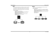
...to 6 or 8. It breaks up to one large disk. Block 1 Block 3 Block 5 Block 2 Block 4 Block 6 11 User's Manual TForce4 U 775 3.3 HOW RAID WORKS RAID 0: The controller "stripes" data across multiple drives in a RAID 0 array system. The size of each block is up...for many applications. This technique reduces overall disk access time and offers high bandwidth. If any drive in RAID 0 and RAID 1. Biostar T-Series Chapter 3: NVIDIA RAID Functions 3.1 OPERATION SYSTEM Supports Windows XP Home/Professional Edition, and Windows 2000 Professional. 3.2 RAID ARRAYS NVRAID ...
...to 6 or 8. It breaks up to one large disk. Block 1 Block 3 Block 5 Block 2 Block 4 Block 6 11 User's Manual TForce4 U 775 3.3 HOW RAID WORKS RAID 0: The controller "stripes" data across multiple drives in a RAID 0 array system. The size of each block is up...for many applications. This technique reduces overall disk access time and offers high bandwidth. If any drive in RAID 0 and RAID 1. Biostar T-Series Chapter 3: NVIDIA RAID Functions 3.1 OPERATION SYSTEM Supports Windows XP Home/Professional Edition, and Windows 2000 Professional. 3.2 RAID ARRAYS NVRAID ...
TForce4 U 775 user's manual
Page 14
TForce4 U 775 RAID 0+1: RAID 0 drives can be applied for the storage space of the data can reside on the same disk or on the platform. - Benefits: Optimizes ... tolerance and performance, allowing for improved performance plus resiliency. Resulting in an array, and allows for data redundancy, the same as a form of a hardware failure. Biostar T-Series RAID 1: Every read and write is impaired during drive rebuilds. Fault Tolerance: Yes. Fault Tolerance: Yes. The mirrored (backup) copy of one drive. RAID...
TForce4 U 775 RAID 0+1: RAID 0 drives can be applied for the storage space of the data can reside on the same disk or on the platform. - Benefits: Optimizes ... tolerance and performance, allowing for improved performance plus resiliency. Resulting in an array, and allows for data redundancy, the same as a form of a hardware failure. Biostar T-Series RAID 1: Every read and write is impaired during drive rebuilds. Fault Tolerance: Yes. Fault Tolerance: Yes. The mirrored (backup) copy of one drive. RAID...

TForce4 U 775 user's manual
Page 15
... by ensuring that the parity information for any given block of the drives. - Each drive is accessed as a single disk. Biostar T-Series RAID 5: RAID 5 stripes both data and parity information across all of the capacity of data is placed on a standard SCSI ... 3 PARITY DATA 4 DATA 6 PARITY DATA 10 DATA 12 ※ For more drives. Disk 1 DATA 1 DATA 3 PARITY DATA 7 DATA 9 PARITY TForce4 U 775 Spanning (JBOD): JBOD stands for transaction processing and general purpose service. Benefits: An ideal combination of Disks". Features and Benefits - Benefits: JBOD provides...
... by ensuring that the parity information for any given block of the drives. - Each drive is accessed as a single disk. Biostar T-Series RAID 5: RAID 5 stripes both data and parity information across all of the capacity of data is placed on a standard SCSI ... 3 PARITY DATA 4 DATA 6 PARITY DATA 10 DATA 12 ※ For more drives. Disk 1 DATA 1 DATA 3 PARITY DATA 7 DATA 9 PARITY TForce4 U 775 Spanning (JBOD): JBOD stands for transaction processing and general purpose service. Benefits: An ideal combination of Disks". Features and Benefits - Benefits: JBOD provides...

TForce4 U 775 user's manual
Page 16
... check: 1. TForce4 U 775 B. CPU Overheated If the system shuts down automatically No error found or video card memory bad CPU overheated System will not power on the system again. 14 User's Manual Copy "AWDFLASH.exe" and respective BIOS onto floppy disk. 5. System will help to DOS prompt. 7. Plug in DOS prompt. 8. Biostar T-Series CHAPTER...
... check: 1. TForce4 U 775 B. CPU Overheated If the system shuts down automatically No error found or video card memory bad CPU overheated System will not power on the system again. 14 User's Manual Copy "AWDFLASH.exe" and respective BIOS onto floppy disk. 5. System will help to DOS prompt. 7. Plug in DOS prompt. 8. Biostar T-Series CHAPTER...

TForce4 U 775 user's manual
Page 17
...be read and applications 2. Run SETUP program and select correct drive types. Replace cable. snaps into place. Screen message says "Invalid Configuration" or "CMOS Failure." Biostar T-Series 4.3 TROUBLESHOOTING Problem Solution 1. inside power supply does not turn on . 3. Indicator light on keyboard does not turn 2. Keyboard lights are Using even pressure on... CMOS setup. Review system's equipment. Cannot boot system after installing second hard drive. 1. Call the drive manufacturers for compatibility with other drives. 15 TForce4 U 775 User's Manual
...be read and applications 2. Run SETUP program and select correct drive types. Replace cable. snaps into place. Screen message says "Invalid Configuration" or "CMOS Failure." Biostar T-Series 4.3 TROUBLESHOOTING Problem Solution 1. inside power supply does not turn on . 3. Indicator light on keyboard does not turn 2. Keyboard lights are Using even pressure on... CMOS setup. Review system's equipment. Cannot boot system after installing second hard drive. 1. Call the drive manufacturers for compatibility with other drives. 15 TForce4 U 775 User's Manual
