

TForce4 U 775 user's manual
Page 1
... Cable x 1 (optional) User's Manual x 1 Overclock Guide x 1 Serial ATA Cable x 1 Fully Setup Driver CD x 1 Rear I/O Panel for any purpose. The content of their respective companies. Biostar T-Series TForce4 U 775 FCC Information and Copyright This equipment has been tested and found in this user's manual. This equipment generates, uses and can radiate radio frequency energy...
... Cable x 1 (optional) User's Manual x 1 Overclock Guide x 1 Serial ATA Cable x 1 Fully Setup Driver CD x 1 Rear I/O Panel for any purpose. The content of their respective companies. Biostar T-Series TForce4 U 775 FCC Information and Copyright This equipment has been tested and found in this user's manual. This equipment generates, uses and can radiate radio frequency energy...

TForce4 U 775 user's manual
Page 2
... 3.1 OPERATION SYSTEM 11 3.2 RAID ARRAYS 11 3.3 HOW RAID WORKS 11 CHAPTER 4: USEFUL HELP 14 4.1 AWARD BIOS BEEP CODE 14 4.2 EXTRA INFORMATION 14 A. Memory Capacity 4 2.3 PERIPHERALS 4 A. Biostar T-Series TForce4 U 775 PACKAGE CHECKLIST I /O Slots 4 B.
... 3.1 OPERATION SYSTEM 11 3.2 RAID ARRAYS 11 3.3 HOW RAID WORKS 11 CHAPTER 4: USEFUL HELP 14 4.1 AWARD BIOS BEEP CODE 14 4.2 EXTRA INFORMATION 14 A. Memory Capacity 4 2.3 PERIPHERALS 4 A. Biostar T-Series TForce4 U 775 PACKAGE CHECKLIST I /O Slots 4 B.
TForce4 U 775 user's manual
Page 3
... Bridge: nForce 430 / nForce 410. - Supports NVIDIA Secure Networking Processor. (nForce 430 Only) Operating Systems Supports Windows 2000 and Windows XP. Biostar T-Series TForce4 U 775 Chapter 1: Introduction 1.1 MOTHERBOARD FEATURES CPU Supports LGA 775. Maximum memory capacity is 4GB, supporting 4 DIMM sockets. Environment Control initiatives, H/W Monitor Fan Speed Controller ITE's "Smart Guardian...
... Bridge: nForce 430 / nForce 410. - Supports NVIDIA Secure Networking Processor. (nForce 430 Only) Operating Systems Supports Windows 2000 and Windows XP. Biostar T-Series TForce4 U 775 Chapter 1: Introduction 1.1 MOTHERBOARD FEATURES CPU Supports LGA 775. Maximum memory capacity is 4GB, supporting 4 DIMM sockets. Environment Control initiatives, H/W Monitor Fan Speed Controller ITE's "Smart Guardian...

TForce4 U 775 user's manual
Page 4
IDE2 IDE1 NForce 4 SPP Ultra JNBFAN1 JDDR2_OV>3V (optional) FDD1 2 DDR2_A1 DDR2_A2 DDR2_B1 DDR2_B2 JCFAN1 User's Manual Biostar T-Series 1.2 LAYOUT AND COMPONENTS Super I/O LED_D1 LED_D2 JSPDIF_IN1 (optional) Codec JCDIN1 LAN JAUDIO1 JUSBLAN1 JUSB3 JFAUDIO1 JATXPWR1 TForce4 U 775 JPRNT1 JCOM1 JKBV1 JKBMS1 JATXPWR2 LGA775 CPU1 PCI-Ex16-1 PCI-Ex1_1 PCI-Ex1_2 PCI1 PCI2 PCI3 PCI4 JSPDIF_OUT1 JSFAN2 BIOS JUSB1 JUSB2 JPANEL1 nForce 430 / nForce 410 JCI1 SATA1 IR Heade r (Op ti onal ) SATA4 JCMOS1 BAT1 JSFAN1 SATA2 SATA3 Note: ■ represents the 1st pin.
IDE2 IDE1 NForce 4 SPP Ultra JNBFAN1 JDDR2_OV>3V (optional) FDD1 2 DDR2_A1 DDR2_A2 DDR2_B1 DDR2_B2 JCFAN1 User's Manual Biostar T-Series 1.2 LAYOUT AND COMPONENTS Super I/O LED_D1 LED_D2 JSPDIF_IN1 (optional) Codec JCDIN1 LAN JAUDIO1 JUSBLAN1 JUSB3 JFAUDIO1 JATXPWR1 TForce4 U 775 JPRNT1 JCOM1 JKBV1 JKBMS1 JATXPWR2 LGA775 CPU1 PCI-Ex16-1 PCI-Ex1_1 PCI-Ex1_2 PCI1 PCI2 PCI3 PCI4 JSPDIF_OUT1 JSFAN2 BIOS JUSB1 JUSB2 JPANEL1 nForce 430 / nForce 410 JCI1 SATA1 IR Heade r (Op ti onal ) SATA4 JCMOS1 BAT1 JSFAN1 SATA2 SATA3 Note: ■ represents the 1st pin.

TForce4 U 775 user's manual
Page 5
Connect the CPU FAN power cable into the JCFAN1. B. User's Manual Step 2-2: TForce4 U 775 Step 3: Hold the CPU down firmly, and then lower the lever to locked position to a 90-degree angle. The CPU will fit only in the ... assembly on the CPU and buckle it on CPU should be damaged. When the CPU is Ground and should point towards this triangular cut edge. Biostar T-Series Chapter 2: Hardware Installations 2.1 CPU ASSEMBLY A. pin cap Step 1: Pull the socket locking lever out from the socket and then raise the lever up to...
Connect the CPU FAN power cable into the JCFAN1. B. User's Manual Step 2-2: TForce4 U 775 Step 3: Hold the CPU down firmly, and then lower the lever to locked position to a 90-degree angle. The CPU will fit only in the ... assembly on the CPU and buckle it on CPU should be damaged. When the CPU is Ground and should point towards this triangular cut edge. Biostar T-Series Chapter 2: Hardware Installations 2.1 CPU ASSEMBLY A. pin cap Step 1: Pull the socket locking lever out from the socket and then raise the lever up to...

TForce4 U 775 user's manual
Page 6
... DDR Module 256MB/512MB/1GB *1 256MB/512MB/1GB *1 256MB/512MB/1GB *1 256MB/512MB/1GB *1 Total Memory Size Max is properly seated. B. Biostar T-Series 2.2 SYSTEM MEMORY DDR2_A1 DDR2_A2 DDR2_B1 DDR2_B2 TForce4 U 775 2.3 PERIPHERALS A. The first hard drive should always be connected to four hard disk drives. Align a DIMM on the slot. 2. This connector supports...
... DDR Module 256MB/512MB/1GB *1 256MB/512MB/1GB *1 256MB/512MB/1GB *1 256MB/512MB/1GB *1 Total Memory Size Max is properly seated. B. Biostar T-Series 2.2 SYSTEM MEMORY DDR2_A1 DDR2_A2 DDR2_B1 DDR2_B2 TForce4 U 775 2.3 PERIPHERALS A. The first hard drive should always be connected to four hard disk drives. Align a DIMM on the slot. 2. This connector supports...

TForce4 U 775 user's manual
Page 7
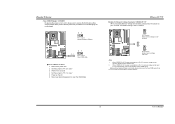
...opened Pin closed Pin1-2 closed ", if not, that means the jumper is designated as 32 bits. PCI-Ex16-1 PCI-Ex1_1 PCI-Ex1_2 TForce4 U 775 B. PCI stands for expansion cards. PCI-Ex1_1/PCI-Ex1_2: - Connectors and Headers: How to setup Jumpers The illustration shows how to ...connector on pins, the jumper is "closed ATX Power Source Connector: JATXPWR1 JATXPWR1 allows user to set up to 250MB/s per direction. Biostar T-Series Peripheral Component Interconnect Slots: PCI1~PCI4 This motherboard is a bus standard for Peripheral Component Interconnect, and it is equipped with 4 ...
...opened Pin closed Pin1-2 closed ", if not, that means the jumper is designated as 32 bits. PCI-Ex16-1 PCI-Ex1_1 PCI-Ex1_2 TForce4 U 775 B. PCI stands for expansion cards. PCI-Ex1_1/PCI-Ex1_2: - Connectors and Headers: How to setup Jumpers The illustration shows how to ...connector on pins, the jumper is "closed ATX Power Source Connector: JATXPWR1 JATXPWR1 allows user to set up to 250MB/s per direction. Biostar T-Series Peripheral Component Interconnect Slots: PCI1~PCI4 This motherboard is a bus standard for Peripheral Component Interconnect, and it is equipped with 4 ...

TForce4 U 775 user's manual
Page 8
...Right 12 Right line in/ Rear speaker Right 13 Left line in/ Rear speaker Left 14 Left line in/ Rear speaker Left 6 User's Manual TForce4 U 775 Front Panel Audio-out Header: JAUDIOF1 This connector will allow user to support this function "Power-on system via keyboard and mouse," JKBV1 jumper cap.... 21 3 4 Pin Assignment 1 +12V 2 +12V 3 Ground 4 Ground Power Source Header for PS/2 Keyboard/Mouse: JKBV1 Pin 1-2 Close: +5V for PS/2 keyboard and mouse. Biostar T-Series ATX Power Source Connector: JATXPWR2 By connecting JATXPWR2, it will disable the output on Pin 2-3.
...Right 12 Right line in/ Rear speaker Right 13 Left line in/ Rear speaker Left 14 Left line in/ Rear speaker Left 6 User's Manual TForce4 U 775 Front Panel Audio-out Header: JAUDIOF1 This connector will allow user to support this function "Power-on system via keyboard and mouse," JKBV1 jumper cap.... 21 3 4 Pin Assignment 1 +12V 2 +12V 3 Ground 4 Ground Power Source Header for PS/2 Keyboard/Mouse: JKBV1 Pin 1-2 Close: +5V for PS/2 keyboard and mouse. Biostar T-Series ATX Power Source Connector: JATXPWR2 By connecting JATXPWR2, it will disable the output on Pin 2-3.

TForce4 U 775 user's manual
Page 9
... 10 9 Pin Assignment 1 +5V (fused) 2 +5V (fused) 3 USB4 USB5 USB+ 6 USB+ 7 Ground 8 Ground 9 Key 10 NC TForce4 U 775 Digital Audio-out Connector: JSPDIF_OUT1 This connector allows users to connect the PCI bracket SPDIF input header. Biostar T-Series CD-ROM Audio-in Connector: JCDIN1 This connector allows user to connect the audio source from...
... 10 9 Pin Assignment 1 +5V (fused) 2 +5V (fused) 3 USB4 USB5 USB+ 6 USB+ 7 Ground 8 Ground 9 Key 10 NC TForce4 U 775 Digital Audio-out Connector: JSPDIF_OUT1 This connector allows users to connect the PCI bracket SPDIF input header. Biostar T-Series CD-ROM Audio-in Connector: JCDIN1 This connector allows user to connect the audio source from...

TForce4 U 775 user's manual
Page 10
... case open signal 2 Ground 2 1 8 User's Manual It satisfies the SATA 2.0 spec with transfer rate of 3.0 Gb/s. Biostar T-Series JPANEL1: Header for Front Panel Facilities This 16-pin connector includes Power-on button IrDA Connector (Optional) TForce4 U 775 Serial ATA Connectors: JSATA1~JSATA4 With the SATA Controller provided in the chipset, this motherboard supports...
... case open signal 2 Ground 2 1 8 User's Manual It satisfies the SATA 2.0 spec with transfer rate of 3.0 Gb/s. Biostar T-Series JPANEL1: Header for Front Panel Facilities This 16-pin connector includes Power-on button IrDA Connector (Optional) TForce4 U 775 Serial ATA Connectors: JSATA1~JSATA4 With the SATA Controller provided in the chipset, this motherboard supports...
TForce4 U 775 user's manual
Page 11
... the jumper to 3V. (Consult your desired password or clear the CMOS data. Reset your DDR memory module supplier) 9 User's Manual Biostar T-Series Clear CMOS Header: JCMOS1 By placing the jumper on Pin 2-3, memory voltage can 't be adjusted under CMOS setup. 2. The Default... setting is placed on the AC. 6. Power on Pin 1-2, memory voltage will be manually adjusted under COMS setup. TForce4 U 775 Header for five seconds. 4. Note: 1. When "JDDR_OV>3V" jumper cap is Pin 2-3 Closed. 1 3 Pin 1-2 close: Fixed memory voltage at 3....
... the jumper to 3V. (Consult your desired password or clear the CMOS data. Reset your DDR memory module supplier) 9 User's Manual Biostar T-Series Clear CMOS Header: JCMOS1 By placing the jumper on Pin 2-3, memory voltage can 't be adjusted under CMOS setup. 2. The Default... setting is placed on the AC. 6. Power on Pin 1-2, memory voltage will be manually adjusted under COMS setup. TForce4 U 775 Header for five seconds. 4. Note: 1. When "JDDR_OV>3V" jumper cap is Pin 2-3 Closed. 1 3 Pin 1-2 close: Fixed memory voltage at 3....

TForce4 U 775 user's manual
Page 12
Biostar T-Series On-Board LED Indicators There are 4 LED indicators on diagnostics. LED_D1 LED_D2 LED_D1 and LED_D2: These 2 LED indicate system power on the motherboard to the table below for different messages: LED_D2 LED_D1 Message ON ON Normal OFF ON Memory Error ON OFF VGA Error OFF OFF Abnormal: CPU / chipset error 10 TForce4 U 775 User's Manual Please refer to show system status.
Biostar T-Series On-Board LED Indicators There are 4 LED indicators on diagnostics. LED_D1 LED_D2 LED_D1 and LED_D2: These 2 LED indicate system power on the motherboard to the table below for different messages: LED_D2 LED_D1 Message ON ON Normal OFF ON Memory Error ON OFF VGA Error OFF OFF Abnormal: CPU / chipset error 10 TForce4 U 775 User's Manual Please refer to show system status.

TForce4 U 775 user's manual
Page 13
Biostar T-Series Chapter 3: NVIDIA RAID Functions 3.1 OPERATION SYSTEM Supports Windows XP Home/Professional Edition, and Windows 2000 Professional. 3.2 RAID ARRAYS NVRAID supports the following types of ... disk capacity. RAID 0+1: RAID 0+1 combines the techniques used in a RAID 0 array system. RAID 5: RAID 5 provides fault tolerance and better utilization of different sizes in parallel. TForce4 U 775 3.3 HOW RAID WORKS RAID 0: The controller "stripes" data across multiple drives in to 6 or 8. Features and Benefits Drives: Minimum 1, and maximum is lost. ...
Biostar T-Series Chapter 3: NVIDIA RAID Functions 3.1 OPERATION SYSTEM Supports Windows XP Home/Professional Edition, and Windows 2000 Professional. 3.2 RAID ARRAYS NVRAID supports the following types of ... disk capacity. RAID 0+1: RAID 0+1 combines the techniques used in a RAID 0 array system. RAID 5: RAID 5 provides fault tolerance and better utilization of different sizes in parallel. TForce4 U 775 3.3 HOW RAID WORKS RAID 0: The controller "stripes" data across multiple drives in to 6 or 8. Features and Benefits Drives: Minimum 1, and maximum is lost. ...
TForce4 U 775 user's manual
Page 14
... if the active volume or drive is impaired during drive rebuilds. Fault Tolerance: Yes. TForce4 U 775 RAID 0+1: RAID 0 drives can be applied for high-availability solutions, or as RAID level 1. - May be mirrored using RAID 1 techniques. Biostar T-Series RAID 1: Every read and write is actually carried out in parallel across 2 disk drives...
... if the active volume or drive is impaired during drive rebuilds. Fault Tolerance: Yes. TForce4 U 775 RAID 0+1: RAID 0 drives can be applied for high-availability solutions, or as RAID level 1. - May be mirrored using RAID 1 techniques. Biostar T-Series RAID 1: Every read and write is actually carried out in parallel across 2 disk drives...

TForce4 U 775 user's manual
Page 15
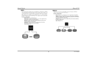
... 3 PARITY DATA 4 DATA 6 PARITY DATA 10 DATA 12 ※ For more drives. Disk 1 DATA 1 DATA 3 PARITY DATA 7 DATA 9 PARITY TForce4 U 775 Spanning (JBOD): JBOD stands for transaction processing and general purpose service. Benefits: An ideal combination of the difficulty in using all the drives in.... Benefits: JBOD provides the ability to make one big drive. - Write performance can be CPU intensive. Fault Tolerance: Yes. Biostar T-Series RAID 5: RAID 5 stripes both data and parity information across all of the capacity of Disks". Each drive is placed on a ...
... 3 PARITY DATA 4 DATA 6 PARITY DATA 10 DATA 12 ※ For more drives. Disk 1 DATA 1 DATA 3 PARITY DATA 7 DATA 9 PARITY TForce4 U 775 Spanning (JBOD): JBOD stands for transaction processing and general purpose service. Benefits: An ideal combination of the difficulty in using all the drives in.... Benefits: JBOD provides the ability to make one big drive. - Write performance can be CPU intensive. Fault Tolerance: Yes. Biostar T-Series RAID 5: RAID 5 stripes both data and parity information across all of the capacity of Disks". Each drive is placed on a ...

TForce4 U 775 user's manual
Page 16
... power supply for a few seconds. 2. Clear the CMOS data. (See "JCMOS1: Clear CMOS Header" section) 2. BIOS Update After you can: 1. TForce4 U 775 B. Or you fail to update BIOS or BIOS is rotating normally. 3. If the following message is fulfilling the CPU speed. Type "Awdflash xxxx.bf/sn...No error found or video card memory bad CPU overheated System will shut down automatically after power on the system again. 14 User's Manual Biostar T-Series CHAPTER 4: USEFUL HELP 4.1 AWARD BIOS BEEP CODE Beep Sound One long beep followed by a virus, the Boot-Block function ...
... power supply for a few seconds. 2. Clear the CMOS data. (See "JCMOS1: Clear CMOS Header" section) 2. BIOS Update After you can: 1. TForce4 U 775 B. Or you fail to update BIOS or BIOS is rotating normally. 3. If the following message is fulfilling the CPU speed. Type "Awdflash xxxx.bf/sn...No error found or video card memory bad CPU overheated System will shut down automatically after power on the system again. 14 User's Manual Biostar T-Series CHAPTER 4: USEFUL HELP 4.1 AWARD BIOS BEEP CODE Beep Sound One long beep followed by a virus, the Boot-Block function ...

TForce4 U 775 user's manual
Page 17
...applications and data using backup disks. Make sure correct information is spinning. Cannot boot system after installing second hard drive. 1. Biostar T-Series 4.3 TROUBLESHOOTING Problem Solution 1. All hard disks are securely plugged in the standard CMOS setup. Back up the hard ...drive is securely Power light don't illuminate, fan plugged in setup. Call the drive manufacturers for compatibility with other drives. 15 TForce4 U 775 User's Manual Make sure power cable is extremely important. Contact technical support. 2. check the drive type in ; System only boots...
...applications and data using backup disks. Make sure correct information is spinning. Cannot boot system after installing second hard drive. 1. Biostar T-Series 4.3 TROUBLESHOOTING Problem Solution 1. All hard disks are securely plugged in the standard CMOS setup. Back up the hard ...drive is securely Power light don't illuminate, fan plugged in setup. Call the drive manufacturers for compatibility with other drives. 15 TForce4 U 775 User's Manual Make sure power cable is extremely important. Contact technical support. 2. check the drive type in ; System only boots...
