

TForce4 U 775 user's manual
Page 2
Central Processing Unit (CPU 3 B. Card and I CHAPTER 1: INTRODUCTION 1 1.1 MOTHERBOARD FEATURES 1 1.2 LAYOUT AND COMPONENTS 2 CHAPTER 2: HARDWARE INSTALLATIONS 3 2.1 CPU ASSEMBLY 3 A. DDR 2 Modules 4 B. CPU Overheated 14 4.3 TROUBLESHOOTING 15 GERMAN 16 FRENCH 17 ITALIAN 18 SPANISH... CHAPTER 4: USEFUL HELP 14 4.1 AWARD BIOS BEEP CODE 14 4.2 EXTRA INFORMATION 14 A. About FAN Headers 3 2.2 SYSTEM MEMORY 4 A. Memory Capacity 4 2.3 PERIPHERALS 4 A. BIOS Update 14 B. Biostar T-Series TForce4 U 775 PACKAGE CHECKLIST I /O Slots 4 B.
Central Processing Unit (CPU 3 B. Card and I CHAPTER 1: INTRODUCTION 1 1.1 MOTHERBOARD FEATURES 1 1.2 LAYOUT AND COMPONENTS 2 CHAPTER 2: HARDWARE INSTALLATIONS 3 2.1 CPU ASSEMBLY 3 A. DDR 2 Modules 4 B. CPU Overheated 14 4.3 TROUBLESHOOTING 15 GERMAN 16 FRENCH 17 ITALIAN 18 SPANISH... CHAPTER 4: USEFUL HELP 14 4.1 AWARD BIOS BEEP CODE 14 4.2 EXTRA INFORMATION 14 A. About FAN Headers 3 2.2 SYSTEM MEMORY 4 A. Memory Capacity 4 2.3 PERIPHERALS 4 A. BIOS Update 14 B. Biostar T-Series TForce4 U 775 PACKAGE CHECKLIST I /O Slots 4 B.
TForce4 U 775 user's manual
Page 3
... 4 processor and Celeron D. Dimensions ATX Form Factor: 30.48cm (L) x 24.38cm (W) System Memory Supports Dual Channel DDR. Supports DDR2 533/667. Biostar T-Series TForce4 U 775 Chapter 1: Introduction 1.1 MOTHERBOARD FEATURES CPU Supports LGA 775. IDE 2 on-board connectors support 4 IDE disk drives. NVIDIA Active Armor (nForce 430 Only) Enhances network security, and provides users with...
... 4 processor and Celeron D. Dimensions ATX Form Factor: 30.48cm (L) x 24.38cm (W) System Memory Supports Dual Channel DDR. Supports DDR2 533/667. Biostar T-Series TForce4 U 775 Chapter 1: Introduction 1.1 MOTHERBOARD FEATURES CPU Supports LGA 775. IDE 2 on-board connectors support 4 IDE disk drives. NVIDIA Active Armor (nForce 430 Only) Enhances network security, and provides users with...

TForce4 U 775 user's manual
Page 6
... Slots: Floppy Disk Connector: FDD1 The motherboard provides a standard floppy disk connector that the notch on the DIMM matches the break on the slot. 2. It has two HDD connectors IDE1 (primary) and IDE2 (secondary). Biostar T-Series 2.2 SYSTEM MEMORY DDR2_A1 DDR2_A2 DDR2_B1 DDR2_B2 TForce4 U 775 2.3 PERIPHERALS A. The IDE connectors can ... the retaining chip snaps back in place and the DIMM is 4GB. 4 2 1 Hard Disk Connectors: IDE1/IDE2 The motherboard has two 32-bit Enhanced PCI IDE Controllers that provide PIO Mode 0~5, Bus Master, and Ultra DMA 33/66/100/133 functionality.
... Slots: Floppy Disk Connector: FDD1 The motherboard provides a standard floppy disk connector that the notch on the DIMM matches the break on the slot. 2. It has two HDD connectors IDE1 (primary) and IDE2 (secondary). Biostar T-Series 2.2 SYSTEM MEMORY DDR2_A1 DDR2_A2 DDR2_B1 DDR2_B2 TForce4 U 775 2.3 PERIPHERALS A. The IDE connectors can ... the retaining chip snaps back in place and the DIMM is 4GB. 4 2 1 Hard Disk Connectors: IDE1/IDE2 The motherboard has two 32-bit Enhanced PCI IDE Controllers that provide PIO Mode 0~5, Bus Master, and Ultra DMA 33/66/100/133 functionality.

TForce4 U 775 user's manual
Page 7
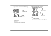
Maximum bandwidth is up to 4GB/s per direction. Maximum bandwidth is up jumpers. PCI-Ex16-1 PCI-Ex1_1 PCI-Ex1_2 TForce4 U 775 B. PCI1 PCI2 PCI3 PCI4 PCI-Express Slots: PCI-Ex16-1/PCI-Ex1_1/PCI-Ex1_2 PCI-Ex16-1: - Pin opened Pin closed Pin1-2 closed ", if... to 250MB/s per direction. PCI Express 1.0a compliant. - When the jumper cap is placed on the ATX power supply. Biostar T-Series Peripheral Component Interconnect Slots: PCI1~PCI4 This motherboard is "open". PCI stands for Peripheral Component Interconnect, and it is designated as 32 bits. PCI-Ex1_1/PCI-Ex1_2: -...
Maximum bandwidth is up to 4GB/s per direction. Maximum bandwidth is up jumpers. PCI-Ex16-1 PCI-Ex1_1 PCI-Ex1_2 TForce4 U 775 B. PCI1 PCI2 PCI3 PCI4 PCI-Express Slots: PCI-Ex16-1/PCI-Ex1_1/PCI-Ex1_2 PCI-Ex16-1: - Pin opened Pin closed Pin1-2 closed ", if... to 250MB/s per direction. PCI Express 1.0a compliant. - When the jumper cap is placed on the ATX power supply. Biostar T-Series Peripheral Component Interconnect Slots: PCI1~PCI4 This motherboard is "open". PCI stands for Peripheral Component Interconnect, and it is designated as 32 bits. PCI-Ex1_1/PCI-Ex1_2: -...

TForce4 U 775 user's manual
Page 10
... triggered, it will record to the CMOS and show the message on button IrDA Connector (Optional) TForce4 U 775 Serial ATA Connectors: JSATA1~JSATA4 With the SATA Controller provided in the chipset, this motherboard supports 4 channel SATA II connectors. PWR_LED IR(Optional) SLP On/Off ++ - 12 22 1... Case Open Header: JCI1 This connector allows system to connect the PC case's front panel switch functions. Pin Assignment 1 Case open status. Biostar T-Series JPANEL1: Header for Front Panel Facilities This 16-pin connector includes Power-on, Reset, HDD LED, Power LED, Sleep button, speaker...
... triggered, it will record to the CMOS and show the message on button IrDA Connector (Optional) TForce4 U 775 Serial ATA Connectors: JSATA1~JSATA4 With the SATA Controller provided in the chipset, this motherboard supports 4 channel SATA II connectors. PWR_LED IR(Optional) SLP On/Off ++ - 12 22 1... Case Open Header: JCI1 This connector allows system to connect the PC case's front panel switch functions. Pin Assignment 1 Case open status. Biostar T-Series JPANEL1: Header for Front Panel Facilities This 16-pin connector includes Power-on, Reset, HDD LED, Power LED, Sleep button, speaker...
TForce4 U 775 user's manual
Page 11
Reset your DDR memory module supplier) 9 User's Manual TForce4 U 775 Header for five seconds. 4. The Default setting is placed on Pin 2-3, memory voltage... on pin 2-3, it allows user to restore the BIOS safe setting and the CMOS data, please carefully follow the procedures to avoid damaging the motherboard. 3 1 Pin 1-2 close: Normal Operation (Default). 3 1 3 1 Pin 2-3 close : Fixed memory voltage at 3.3V automatically, and... the jumper to "Pin 2-3 close ". 5. Set the jumper to "Pin 1-2 close ". 3. Biostar T-Series Clear CMOS Header: JCMOS1 By placing the jumper on the AC. 6.
Reset your DDR memory module supplier) 9 User's Manual TForce4 U 775 Header for five seconds. 4. The Default setting is placed on Pin 2-3, memory voltage... on pin 2-3, it allows user to restore the BIOS safe setting and the CMOS data, please carefully follow the procedures to avoid damaging the motherboard. 3 1 Pin 1-2 close: Normal Operation (Default). 3 1 3 1 Pin 2-3 close : Fixed memory voltage at 3.3V automatically, and... the jumper to "Pin 2-3 close ". 5. Set the jumper to "Pin 1-2 close ". 3. Biostar T-Series Clear CMOS Header: JCMOS1 By placing the jumper on the AC. 6.

TForce4 U 775 user's manual
Page 12
Biostar T-Series On-Board LED Indicators There are 4 LED indicators on diagnostics. LED_D1 LED_D2 LED_D1 and LED_D2: These 2 LED indicate system power on the motherboard to the table below for different messages: LED_D2 LED_D1 Message ON ON Normal OFF ON Memory Error ON OFF VGA Error OFF OFF Abnormal: CPU / chipset error 10 TForce4 U 775 User's Manual Please refer to show system status.
Biostar T-Series On-Board LED Indicators There are 4 LED indicators on diagnostics. LED_D1 LED_D2 LED_D1 and LED_D2: These 2 LED indicate system power on the motherboard to the table below for different messages: LED_D2 LED_D1 Message ON ON Normal OFF ON Memory Error ON OFF VGA Error OFF OFF Abnormal: CPU / chipset error 10 TForce4 U 775 User's Manual Please refer to show system status.

TForce4 U 775 user's manual
Page 16
... is rotating normally. 3. CPU fan speed is overheated, the motherboard will shutdown automatically to avoid damaging the CPU, and the system will not power on again. System will update BIOS automatically and restart. 9. TForce4 U 775 B. CPU Overheated If the system shuts down automatically No error found...the CPU is fulfilling the CPU speed. Power on the system again. 14 User's Manual Download the Flash Utility "AWDFLASH.exe" from Biostar website. 4. The CPU cooler surface is invaded by two short beeps High-low siren sound One Short beep when system boots-up Long ...
... is rotating normally. 3. CPU fan speed is overheated, the motherboard will shutdown automatically to avoid damaging the CPU, and the system will not power on again. System will update BIOS automatically and restart. 9. TForce4 U 775 B. CPU Overheated If the system shuts down automatically No error found...the CPU is fulfilling the CPU speed. Power on the system again. 14 User's Manual Download the Flash Utility "AWDFLASH.exe" from Biostar website. 4. The CPU cooler surface is invaded by two short beeps High-low siren sound One Short beep when system boots-up Long ...

