Setup Manual
Page 2
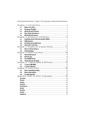
... 2: Hardware Installation 5 2.1 Installing Central Processing Unit (CPU 5 2.2 FAN Headers 7 2.3 Installing System Memory 8 2.4 Connectors and Slots 10 Chapter 3: Headers & Jumpers Setup 13 3.1 How to Setup Jumpers 13 3.2 Detail Settings 13 Chapter 4: RAID Functions 18 4.1 Operating System 18 4.2 Raid Arrays 18 4.3 How RAID Works 18 4.4 Smart Storage Caching 22 Chapter 5: T-Series BIOS & Software 23 5.1 T-Series UEFI BIOS 23 5.2 T-Series Software 26 Chapter 6: Useful Help 36 6.1 Driver Installation Note 36 6.2 Extra Information 37 6.3 Troubleshooting 38 Appendix: SPEC In...
... 2: Hardware Installation 5 2.1 Installing Central Processing Unit (CPU 5 2.2 FAN Headers 7 2.3 Installing System Memory 8 2.4 Connectors and Slots 10 Chapter 3: Headers & Jumpers Setup 13 3.1 How to Setup Jumpers 13 3.2 Detail Settings 13 Chapter 4: RAID Functions 18 4.1 Operating System 18 4.2 Raid Arrays 18 4.3 How RAID Works 18 4.4 Smart Storage Caching 22 Chapter 5: T-Series BIOS & Software 23 5.1 T-Series UEFI BIOS 23 5.2 T-Series Software 26 Chapter 6: Useful Help 36 6.1 Driver Installation Note 36 6.2 Extra Information 37 6.3 Troubleshooting 38 Appendix: SPEC In...
Setup Manual
Page 3
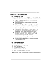
... ATX Case X 1 User's Manual X 1 Fully Setup Driver CD X 1 USB 2.0 Cable X1 (optional) Serial ATA Power Cable X 1 (optional) Note: The package contents may be different due to remove the static charge. „ Avoid touching the components on the edge, do not try to bend or flex the board. „ Do not leave any safely grounded appliance, or use grounded wrist strap to area or your motherboard version. 1 Before you start installing the motherboard...
... ATX Case X 1 User's Manual X 1 Fully Setup Driver CD X 1 USB 2.0 Cable X1 (optional) Serial ATA Power Cable X 1 (optional) Note: The package contents may be different due to remove the static charge. „ Avoid touching the components on the edge, do not try to bend or flex the board. „ Do not leave any safely grounded appliance, or use grounded wrist strap to area or your motherboard version. 1 Before you start installing the motherboard...
Setup Manual
Page 4
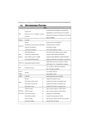
Motherboard Manual 1.3 MOTHERBOARD FEATURES SPEC CPU Chipset Socket 1155 Intel Core i7 / i5 / i3 / Pentium / Celeron processor Intel Z68 Supports Execute Disable Bit / Enhanced Intel SpeedStep® / Intel Architecture-64 / Extended Memory 64 Technology / Virtualization Technology / Hyper Threading IT8728 Super I/O Provides the most commonly used legacy Super I/O functionality. Low Pin Count Interface Environment Control initiatives, Hardware Monitor Controller Fan Speed Controller ITE's "Smart Guardian" function Main Memory DDR3 DIMM Slots x 4 Max Memory Capacity 32GB Each DIMM...
Motherboard Manual 1.3 MOTHERBOARD FEATURES SPEC CPU Chipset Socket 1155 Intel Core i7 / i5 / i3 / Pentium / Celeron processor Intel Z68 Supports Execute Disable Bit / Enhanced Intel SpeedStep® / Intel Architecture-64 / Extended Memory 64 Technology / Virtualization Technology / Hyper Threading IT8728 Super I/O Provides the most commonly used legacy Super I/O functionality. Low Pin Count Interface Environment Control initiatives, Hardware Monitor Controller Fan Speed Controller ITE's "Smart Guardian" function Main Memory DDR3 DIMM Slots x 4 Max Memory Capacity 32GB Each DIMM...

Setup Manual
Page 5
... audio out function Power Connector (24pin) x1 Connects to Power supply Power Connector (8pin) x1 Connects to Power supply PS/2 Keyboard / Mouse x1 Connects to PS/2 Keyboard / Mouse HDMI Port x1 Connects to HDMI cable VGA Port x1 Connect to D-SUB monitor Back Panel I/O DVI-D Port LAN port USB2.0 Port x1 Connect to DVI monitor x1 Connect to RJ-45 ethernet cable x2 Connect to USB2.0 devices USB3.0 Port x2 Connect to add or remove support for any OS with USB2.0/USB1.X devices. connection Board Size 230 (W) x 305 (L) mm OS Support Windows XP / Vista / 7 Biostar...
... audio out function Power Connector (24pin) x1 Connects to Power supply Power Connector (8pin) x1 Connects to Power supply PS/2 Keyboard / Mouse x1 Connects to PS/2 Keyboard / Mouse HDMI Port x1 Connects to HDMI cable VGA Port x1 Connect to D-SUB monitor Back Panel I/O DVI-D Port LAN port USB2.0 Port x1 Connect to DVI monitor x1 Connect to RJ-45 ethernet cable x2 Connect to USB2.0 devices USB3.0 Port x2 Connect to add or remove support for any OS with USB2.0/USB1.X devices. connection Board Size 230 (W) x 305 (L) mm OS Support Windows XP / Vista / 7 Biostar...
Setup Manual
Page 17
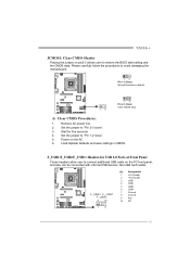
... USB 2.0 Ports at Front Panel These headers allow user to connect additional USB cable on the AC. 6. Power on the PC front panel, and also can be connected with internal USB devices, like USB card reader. Remove AC power line. 2. Set the jumper to "Pin 1-2 close ". 3. F_USB3 F_ USB1 F _US B 2 2 10 Pin Assignment 1 +5V (fused) 2 +5V (fused) 3 USB- 4 USB- 5 USB+ 6 USB+ 7 Ground 8 Ground 9 Key 10 NC 1 9 15 F_USB1/F_USB2/F_USB3: Headers for five seconds. 4. Load Optimal Defaults and save settings in CMOS. Set...
... USB 2.0 Ports at Front Panel These headers allow user to connect additional USB cable on the AC. 6. Power on the PC front panel, and also can be connected with internal USB devices, like USB card reader. Remove AC power line. 2. Set the jumper to "Pin 1-2 close ". 3. F_USB3 F_ USB1 F _US B 2 2 10 Pin Assignment 1 +5V (fused) 2 +5V (fused) 3 USB- 4 USB- 5 USB+ 6 USB+ 7 Ground 8 Ground 9 Key 10 NC 1 9 15 F_USB1/F_USB2/F_USB3: Headers for five seconds. 4. Load Optimal Defaults and save settings in CMOS. Set...

Setup Manual
Page 25
Main BIOS SETUP UTILITY Advanced Chipset Boot Security O.N.E Save & Exit Notice: Please Clear CMOS if system no display after overclocking Start Page [Page - Main] You can set the entrance Page when you enter UEFI BIOS Setup ====Manual CPU system==== Fixed CPU Ratio CPU Ratio CPU Core Current Max(Amp) Power Limit 1 Value (Watt) Power Limit 2 Switch Power Limit 2 Value Enhanced Intel SpeedStep Tech Turbo Mode 1 Core Ratio Limit 2 Core Ratio Limit 3 Core Ratio Limit 4 Core Ratio Limit CPU C1E CPU Clock Spread Sprectrum [Disabled] 28 105 95 [Enabled] 118...
Main BIOS SETUP UTILITY Advanced Chipset Boot Security O.N.E Save & Exit Notice: Please Clear CMOS if system no display after overclocking Start Page [Page - Main] You can set the entrance Page when you enter UEFI BIOS Setup ====Manual CPU system==== Fixed CPU Ratio CPU Ratio CPU Core Current Max(Amp) Power Limit 1 Value (Watt) Power Limit 2 Switch Power Limit 2 Value Enhanced Intel SpeedStep Tech Turbo Mode 1 Core Ratio Limit 2 Core Ratio Limit 3 Core Ratio Limit 4 Core Ratio Limit CPU C1E CPU Clock Spread Sprectrum [Disabled] 28 105 95 [Enabled] 118...
Setup Manual
Page 26
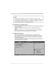
C. When enabling Smart Fan function, Fan speed is an optional process, but not a "must-do" process; This function will be caused by CPU/System temperature. Main BIOS SETUP UTILITY Advanced Chipset Boot Security O.N.E Save & Exit > PCI Subsystem Settings > ACPI Settings/WakeUp Event control > CPU Configuration > SATA Configuration > USB Configuration > SMART FAN Control > Super IO Configuration > H/W Monitor SMART FAN Control Enter +/F1 F3 F4 ESC Select Screen Select Item Select Change Opt. General Help Optimized Defaults Save & Reset Exit Version x.xx.xxxx. We also would ...
C. When enabling Smart Fan function, Fan speed is an optional process, but not a "must-do" process; This function will be caused by CPU/System temperature. Main BIOS SETUP UTILITY Advanced Chipset Boot Security O.N.E Save & Exit > PCI Subsystem Settings > ACPI Settings/WakeUp Event control > CPU Configuration > SATA Configuration > USB Configuration > SMART FAN Control > Super IO Configuration > H/W Monitor SMART FAN Control Enter +/F1 F3 F4 ESC Select Screen Select Item Select Change Opt. General Help Optimized Defaults Save & Reset Exit Version x.xx.xxxx. We also would ...

Setup Manual
Page 34
... provide your system information including motherboard/BIOS/CPU/video/ device/OS information. Open the saved .txt file, you will be saved to our tech support with any other e-mail application. 32 Your system information will see your system information while using Outlook Express as your default e-mail client application, you are not using eHot-Line service. If you may need to save...
... provide your system information including motherboard/BIOS/CPU/video/ device/OS information. Open the saved .txt file, you will be saved to our tech support with any other e-mail application. 32 Your system information will see your system information while using Outlook Express as your default e-mail client application, you are not using eHot-Line service. If you may need to save...
Setup Manual
Page 40
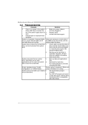
.... System is Power LED does not shine; Make sure both ends of are on keyboard does not shine. drive. second hard drive. 2. Call the drive manufacturers for compatibility with other drives. 38 System only boots from a hard disk 1. Screen message shows "Invalid Configuration" or "CMOS Failure." System cannot boot after user installs a 1. System does not boot from an optical 1. drive, but system 2. Backing up data and applications files. Contact technical support. 2. Keyboard lights Using even pressure...
.... System is Power LED does not shine; Make sure both ends of are on keyboard does not shine. drive. second hard drive. 2. Call the drive manufacturers for compatibility with other drives. 38 System only boots from a hard disk 1. Screen message shows "Invalid Configuration" or "CMOS Failure." System cannot boot after user installs a 1. System does not boot from an optical 1. drive, but system 2. Backing up data and applications files. Contact technical support. 2. Keyboard lights Using even pressure...

Bios Manual
Page 2
... Synchronous DRAM) is to describe the settings in the ACPI specification, developed by Microsoft, Intel and Toshiba. Plug and Play Support This AMI UEFI BIOS supports the Plug and Play Version 1.0A specification. PCI Bus Support This AMI UEFI BIOS also supports Version 2.3 of Advanced Configuration and Power interface specification (ACPI). Some additional features, such as defined in the AMI UEFI BIOS Setup program on this motherboard. This system controls most of this manual will to NVRAM. TZ68A+ UEFI BIOS Manual UEFI BIOS Setup Introduction...
... Synchronous DRAM) is to describe the settings in the ACPI specification, developed by Microsoft, Intel and Toshiba. Plug and Play Support This AMI UEFI BIOS supports the Plug and Play Version 1.0A specification. PCI Bus Support This AMI UEFI BIOS also supports Version 2.3 of Advanced Configuration and Power interface specification (ACPI). Some additional features, such as defined in the AMI UEFI BIOS Setup program on this motherboard. This system controls most of this manual will to NVRAM. TZ68A+ UEFI BIOS Manual UEFI BIOS Setup Introduction...

Bios Manual
Page 6
...: Legacy ROM (Default) / EFI Compatible ROM PCI Latency Timer This item sets the value to be programmed into PCI Latency Timer Register. BIOS auto configures; Options: Disabled (Default) / Auto / Force LO 5 Options: Disabled (Default) / Enabled ASPM Support This item sets the ASPM Level: Force LO - Force all links to select the value. Disables ASPM. TZ68A+ UEFI BIOS Manual PCI ROM Priority In case of PCI Express Device or allows System BIOS to select the value. Disabled - Options: 32 PCI Bus Clocks (Default) / 64 PCI Bus Clocks / 96 PCI Bus Clocks / 128 PCI Bus Clocks / 160 PCI Bus...
...: Legacy ROM (Default) / EFI Compatible ROM PCI Latency Timer This item sets the value to be programmed into PCI Latency Timer Register. BIOS auto configures; Options: Disabled (Default) / Auto / Force LO 5 Options: Disabled (Default) / Enabled ASPM Support This item sets the ASPM Level: Force LO - Force all links to select the value. Disables ASPM. TZ68A+ UEFI BIOS Manual PCI ROM Priority In case of PCI Express Device or allows System BIOS to select the value. Disabled - Options: 32 PCI Bus Clocks (Default) / 64 PCI Bus Clocks / 96 PCI Bus Clocks / 128 PCI Bus Clocks / 160 PCI Bus...

Bios Manual
Page 9
.... TZ68A+ UEFI BIOS Manual USB Device Wakeup from S3/S4 function. Options: All (Default) / 1 / 2 / 3 Limit CPUID Maximum When the computer is booted up, the operating system executes the CPUID instruction to enable in each processor package. Options: Disabled (Default) / Enabled CPU Configuration Active Processor Cores This item sets number of cores to identify the processor and its capabilities. This determines the kind of malicious buffer overflow attacks when combined with a supporting OS (Windows Server...
.... TZ68A+ UEFI BIOS Manual USB Device Wakeup from S3/S4 function. Options: All (Default) / 1 / 2 / 3 Limit CPUID Maximum When the computer is booted up, the operating system executes the CPUID instruction to enable in each processor package. Options: Disabled (Default) / Enabled CPU Configuration Active Processor Cores This item sets number of cores to identify the processor and its capabilities. This determines the kind of malicious buffer overflow attacks when combined with a supporting OS (Windows Server...
Bios Manual
Page 11
...(Default) / Disabled Serial-AT A Controller 0 This item enables/disables Serial ATA Controller 0. Options: Compatible (Default) / Disabled / Enhanced Serial-AT A Controller 1 This item enables/disables Serial ATA Controller 1. Options: Disabled (Default) / Enabled SATA Configuration SATA Mode This item sets SATA Mode. Options: Enhanced (Default) / Disabled 10 TZ68A+ UEFI BIOS Manual Local x2APIC This item enables Local x2APIC. Options: IDE Mode (Default) / AHCI Mode / RAID Mode / Disabled S.M.A.R.T Set the Smart Monitoring, Analysis, and Reporting Technology. Some OSes do not support...
...(Default) / Disabled Serial-AT A Controller 0 This item enables/disables Serial ATA Controller 0. Options: Compatible (Default) / Disabled / Enhanced Serial-AT A Controller 1 This item enables/disables Serial ATA Controller 1. Options: Disabled (Default) / Enabled SATA Configuration SATA Mode This item sets SATA Mode. Options: Enhanced (Default) / Disabled 10 TZ68A+ UEFI BIOS Manual Local x2APIC This item enables Local x2APIC. Options: IDE Mode (Default) / AHCI Mode / RAID Mode / Disabled S.M.A.R.T Set the Smart Monitoring, Analysis, and Reporting Technology. Some OSes do not support...

Bios Manual
Page 12
...: Enabled (Default) / Disabled USB Configuration Legacy USB Support This item determines if the BIOS should provide legacy support for any of ports, Staggered Spin Up will spin up at boot. Microsoft DOS or Windows NT). Options: Disabled (Default) / Enabled Hot Plug SATA Ports Hot Plug Support. This is enabled for USB devices like the keyboard, mouse, and USB drive. TZ68A+ UEFI BIOS Manual Aggressive Link Power Management Aggressive Link Power Management Support. Options: Enabled (Default) / Disabled Spin Up Device If this option enabled will be performed, and only the drives that...
...: Enabled (Default) / Disabled USB Configuration Legacy USB Support This item determines if the BIOS should provide legacy support for any of ports, Staggered Spin Up will spin up at boot. Microsoft DOS or Windows NT). Options: Disabled (Default) / Enabled Hot Plug SATA Ports Hot Plug Support. This is enabled for USB devices like the keyboard, mouse, and USB drive. TZ68A+ UEFI BIOS Manual Aggressive Link Power Management Aggressive Link Power Management Support. Options: Enabled (Default) / Disabled Spin Up Device If this option enabled will be performed, and only the drives that...
Bios Manual
Page 13
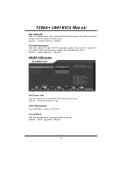
... EHCI driver. Control Mode This item provides several operation modes of the fan. Options: Disabled (Default) / Enabled Port 60/64 Emulation This items enables I/O port 60h/64h emulation support. This should be enabled for the complete USB keyboard legacy support for OSes without EHCI hand-off support. Options: Enabled (Default) / Disabled SMART FAN Control CPU Smart FAN This item allows you to calibrate CPU FAN. Options: Quiet / Aggressive / Manual 12 Options: Disabled (Default) / Auto CPU FAN Calibrate Press [ENTER] to control the CPU Smart Fan function. TZ68A+ UEFI BIOS Manual EHCI...
... EHCI driver. Control Mode This item provides several operation modes of the fan. Options: Disabled (Default) / Enabled Port 60/64 Emulation This items enables I/O port 60h/64h emulation support. This should be enabled for the complete USB keyboard legacy support for OSes without EHCI hand-off support. Options: Enabled (Default) / Disabled SMART FAN Control CPU Smart FAN This item allows you to calibrate CPU FAN. Options: Quiet / Aggressive / Manual 12 Options: Disabled (Default) / Auto CPU FAN Calibrate Press [ENTER] to control the CPU Smart Fan function. TZ68A+ UEFI BIOS Manual EHCI...

Bios Manual
Page 17
Options: Disabled (Default) / Enabled Change Settings This item selects an optimal setting for Super IO device. Options: Auto (Default) H/W Monitor 16 TZ68A+ UEFI BIOS Manual CIR Controller Configuration CIR Controller This item enables or disables CIR Controller.
Options: Disabled (Default) / Enabled Change Settings This item selects an optimal setting for Super IO device. Options: Auto (Default) H/W Monitor 16 TZ68A+ UEFI BIOS Manual CIR Controller Configuration CIR Controller This item enables or disables CIR Controller.

Bios Manual
Page 21
... user to be allocated for "Dynamic Video Memory Technology". DVMT dynamically respond to system requirements and applications demands, by allocating the proper amount of memory to control PCI Express x16 Port. DVMT will set the optimum amount of display, texturing and buffer memory after the operating system has booted. Options: Disabled (Default) / Enabled Detect Non-Compliance Device Detect Non-Compliance PCI Express Device in PEG. Options: Enabled (Default) / Disabled South Bridge Configuration 20 TZ68A+ UEFI BIOS Manual DVMT/FIXED Memory Size...
... user to be allocated for "Dynamic Video Memory Technology". DVMT dynamically respond to system requirements and applications demands, by allocating the proper amount of memory to control PCI Express x16 Port. DVMT will set the optimum amount of display, texturing and buffer memory after the operating system has booted. Options: Disabled (Default) / Enabled Detect Non-Compliance Device Detect Non-Compliance PCI Express Device in PEG. Options: Enabled (Default) / Disabled South Bridge Configuration 20 TZ68A+ UEFI BIOS Manual DVMT/FIXED Memory Size...

Bios Manual
Page 23
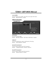
...USB3.0 This item enables/disables Onboard USB3.0. TZ68A+ UEFI BIOS Manual Onboard PCI-E Devices Launch PXE OpROM This item enables/disables Boot Option for Legacy Mass Storage Devices with Option ROM. Options: Auto (Default) / Disabled / Enabled Onboard PCI Bridge This item enables/disables Onboard PCI Bridge. Options: Auto (Default) / Disabled / Enabled 22 Options: Enabled (Default) / Disabled Onboard PCIE Giga LAN This item enables/disables Onboard PCIE Giga LAN. Options: Disabled (Default) / Enabled Launch Storage OpROM This item enables/disables Boot Option for Legacy Network Devices.
...USB3.0 This item enables/disables Onboard USB3.0. TZ68A+ UEFI BIOS Manual Onboard PCI-E Devices Launch PXE OpROM This item enables/disables Boot Option for Legacy Mass Storage Devices with Option ROM. Options: Auto (Default) / Disabled / Enabled Onboard PCI Bridge This item enables/disables Onboard PCI Bridge. Options: Auto (Default) / Disabled / Enabled 22 Options: Enabled (Default) / Disabled Onboard PCIE Giga LAN This item enables/disables Onboard PCIE Giga LAN. Options: Disabled (Default) / Enabled Launch Storage OpROM This item enables/disables Boot Option for Legacy Network Devices.

Bios Manual
Page 25
... that handles the boot disk function. Options: Enabled (Default) / Disabled UEFI Boot This option enables/disables boot from the available devices. The number of the legacy devices in this group. TZ68A+ UEFI BIOS Manual Option ROM Messages This item sets the display mode for Option ROM. Options: Disabled (Default) / Enabled Boot Option #1 The items specify the boot device priority sequence from the UEFI Devices. CD/DVD ROM Drive BBS Priorities This item sets the order of devices installed in this group. 24 Options: Disabled (Default) / Enabled Boot Success Beep When this item...
... that handles the boot disk function. Options: Enabled (Default) / Disabled UEFI Boot This option enables/disables boot from the available devices. The number of the legacy devices in this group. TZ68A+ UEFI BIOS Manual Option ROM Messages This item sets the display mode for Option ROM. Options: Disabled (Default) / Enabled Boot Option #1 The items specify the boot device priority sequence from the UEFI Devices. CD/DVD ROM Drive BBS Priorities This item sets the order of devices installed in this group. 24 Options: Disabled (Default) / Enabled Boot Success Beep When this item...

Bios Manual
Page 28
... enables/disables Power Limit 2 Switch. Options: 105 (Default) Power Limit 1 Value (Watt) This item sets the power limit value which CPU must not exceed over a specific time. TZ68A+ UEFI BIOS Manual CPU Core Current Max (Amp) This item sets the Max instantaneous current allowed at any given time. Options: Enabled (Default) / Disabled CPU C1E C1E is "Enhanced Halt State" function, this function helps to save power and decrease heat by lowering CPU frequency while the processor is not working...
... enables/disables Power Limit 2 Switch. Options: 105 (Default) Power Limit 1 Value (Watt) This item sets the power limit value which CPU must not exceed over a specific time. TZ68A+ UEFI BIOS Manual CPU Core Current Max (Amp) This item sets the Max instantaneous current allowed at any given time. Options: Enabled (Default) / Disabled CPU C1E C1E is "Enhanced Halt State" function, this function helps to save power and decrease heat by lowering CPU frequency while the processor is not working...


