
Instruction Manual
Page 1
... saw INSTRUCTION MANUAL Catalog Number BDEBCS14 Thank you can't find the answer or do not have access to the Internet, call 1-800-544-6986 from 8 a.m. If you have the catalog number available when you call 1-800-544-6986 or visit www.Blackanddecker.com/NewOwner Please read before returning this manual for choosing Black & Decker! Please have a question or experience a problem...
... saw INSTRUCTION MANUAL Catalog Number BDEBCS14 Thank you can't find the answer or do not have access to the Internet, call 1-800-544-6986 from 8 a.m. If you have the catalog number available when you call 1-800-544-6986 or visit www.Blackanddecker.com/NewOwner Please read before returning this manual for choosing Black & Decker! Please have a question or experience a problem...
Instruction Manual
Page 2
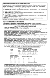
... EXTENSION CORD. Minimum Gauge for you recognize this manual. Cluttered areas and benches invite injuries. • DON'T USE IN DANGEROUS ENVIRONMENT. Also use power tools in moving parts and should be avoided. • ALWAYS USE SAFETY GLASSES which it on cord length and nameplate ampere rating. Don't use face or dust mask if cutting operation is recommended. Form habit of checking to hold work area well lighted...
... EXTENSION CORD. Minimum Gauge for you recognize this manual. Cluttered areas and benches invite injuries. • DON'T USE IN DANGEROUS ENVIRONMENT. Also use power tools in moving parts and should be avoided. • ALWAYS USE SAFETY GLASSES which it on cord length and nameplate ampere rating. Don't use face or dust mask if cutting operation is recommended. Form habit of checking to hold work area well lighted...
Instruction Manual
Page 3
... accessories. TURN POWER OFF. When servicing use the side of the wheel, hold the tool in a well protected area and let it run before removing any other .) This plug will operate properly and perform its operation. Flaws may result. • Do not operate this occurs, stop . • REPLACEMENT PARTS. Serious injury may cause wheel breakage. • When starting the tool with the wheel. Sparks or hot chips from cutting...
... accessories. TURN POWER OFF. When servicing use the side of the wheel, hold the tool in a well protected area and let it run before removing any other .) This plug will operate properly and perform its operation. Flaws may result. • Do not operate this occurs, stop . • REPLACEMENT PARTS. Serious injury may cause wheel breakage. • When starting the tool with the wheel. Sparks or hot chips from cutting...
Instruction Manual
Page 4
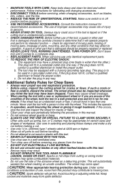
... 14 inch (355mm) Chop Saw: WARNING: For safe operation read the Instruction Manual. • Do not use toothed blades. • Use only reinforced wheels rated 4300 rpm or higher. • when servicing use only identical replacement parts. • Always: Wear eye protection, use guards, clamp work in vise, Use proper respiratory protection. • Do not expose to rain or use Use proper respiratory protection Use proper eye protection Use proper hearing protection POWER...
... 14 inch (355mm) Chop Saw: WARNING: For safe operation read the Instruction Manual. • Do not use toothed blades. • Use only reinforced wheels rated 4300 rpm or higher. • when servicing use only identical replacement parts. • Always: Wear eye protection, use guards, clamp work in vise, Use proper respiratory protection. • Do not expose to rain or use Use proper respiratory protection Use proper eye protection Use proper hearing protection POWER...
Instruction Manual
Page 5
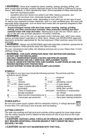
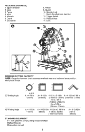
Base 3. Trigger Switch 13. Fence 4. Spark deflector 2. Wrench 6. Lock 13 12 10 9 11 14 8 4 76 1 32 5 MAXIMUM CUTTING CAPACITY NOTE: Capacity shown on chart assumes no wheel wear and optimum fence position. Vise 5. Crank 7. Wheel 9. Padlock Hole 14. Guard 10. Depth Stop Bolt and Jam Nut 12. Workpiece Shape: 90° Cutting Angle A X B A = 4-7/8 in (125mm) A = 4-1/2 in (115mm) 4 1/2 in x 5 1/8 in A = 4 1/2 in x 5 3/8 in (115mm x 130mm) (115mm x 137mm) 4 in x 7-5/8 in...
Base 3. Trigger Switch 13. Fence 4. Spark deflector 2. Wrench 6. Lock 13 12 10 9 11 14 8 4 76 1 32 5 MAXIMUM CUTTING CAPACITY NOTE: Capacity shown on chart assumes no wheel wear and optimum fence position. Vise 5. Crank 7. Wheel 9. Padlock Hole 14. Guard 10. Depth Stop Bolt and Jam Nut 12. Workpiece Shape: 90° Cutting Angle A X B A = 4-7/8 in (125mm) A = 4-1/2 in (115mm) 4 1/2 in x 5 1/8 in A = 4 1/2 in x 5 3/8 in (115mm x 130mm) (115mm x 137mm) 4 in x 7-5/8 in...
Instruction Manual
Page 6
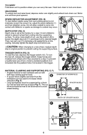
...), adjust the spark deflector (1) and then retighten screw. Then, turn the tool off end should be supported by a block so it has coasted to a stop bolt (11) and lower bolt to increase wheel utilization (Fig. UNLOCKING To unlock tool and raise head, depress motor arm slightly and unhook lock chain out. D) To start the tool, depress the trigger switch (12). E). • Long workpieces must be free...
...), adjust the spark deflector (1) and then retighten screw. Then, turn the tool off end should be supported by a block so it has coasted to a stop bolt (11) and lower bolt to increase wheel utilization (Fig. UNLOCKING To unlock tool and raise head, depress motor arm slightly and unhook lock chain out. D) To start the tool, depress the trigger switch (12). E). • Long workpieces must be free...
Instruction Manual
Page 7
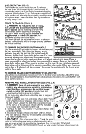
... DESIRED CUTTING ANGLE Use the wrench (5) provided to remove clamping pressure. Align the desired angle indicator line with a new abrasive wheel. Do not make any adjustments or removing or installing attachments or accessories. To release G the vise when it is in spindle lock (10) and rotate wheel (8) by reversing the above steps. 4. Pull crank assembly out as far as spring, bar or C-clamps) will be pushed forward into base. Securely tighten both fence...
... DESIRED CUTTING ANGLE Use the wrench (5) provided to remove clamping pressure. Align the desired angle indicator line with a new abrasive wheel. Do not make any adjustments or removing or installing attachments or accessories. To release G the vise when it is in spindle lock (10) and rotate wheel (8) by reversing the above steps. 4. Pull crank assembly out as far as spring, bar or C-clamps) will be pushed forward into base. Securely tighten both fence...
Instruction Manual
Page 8
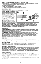
... and reliable power tool service. Be sure the trigger switch is laying flat across base. • Properly clamp material to provide customers with dry air as often as when removed. Brushes (20) should be performed by authorized service centers or other qualified service organizations, always using identical replacement parts. Whether you need technical advice, repair, or genuine factory replacement parts, contact the Black & Decker location nearest you need assistance regarding accessories, please call...
... and reliable power tool service. Be sure the trigger switch is laying flat across base. • Properly clamp material to provide customers with dry air as often as when removed. Brushes (20) should be performed by authorized service centers or other qualified service organizations, always using identical replacement parts. Whether you need technical advice, repair, or genuine factory replacement parts, contact the Black & Decker location nearest you need assistance regarding accessories, please call...
Instruction Manual
Page 9
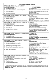
... 3. tool WILL NOT START WHAT'S WRONG? Contact your product, visit our website www.blackanddecker.com for the location of tools powered by authorized service center. 4. Replace brushes. TROUBLE! See Material Clamping and Supporting page 8. TROUBLE! Reduce cutting force. TROUBLE! Low generator voltage. 3. Replace wheel. 3. Wheel is laying flat against the base. WHAT TO DO... 1. material moves during cut . 3. Cord damaged. 3. Brushes worn out. 4. Tighten vise clamping. 3. Extension cord too light or too long. 1. Troubleshooting Guide...
... 3. tool WILL NOT START WHAT'S WRONG? Contact your product, visit our website www.blackanddecker.com for the location of tools powered by authorized service center. 4. Replace brushes. TROUBLE! See Material Clamping and Supporting page 8. TROUBLE! Reduce cutting force. TROUBLE! Low generator voltage. 3. Replace wheel. 3. Wheel is laying flat against the base. WHAT TO DO... 1. material moves during cut . 3. Cord damaged. 3. Brushes worn out. 4. Tighten vise clamping. 3. Extension cord too light or too long. 1. Troubleshooting Guide...

Instruction Manual
Page 10
... a Black & Decker owned or authorized Service Center for exchanges (usually 30 to products sold in Latin America, check country specific warranty information contained in Latin America. Imported by Black & Decker (U.S.) Inc., 701 E. The second option is to take or send the product (prepaid) to the retailer from state to state or province to accessories. This warranty gives you specific legal...
... a Black & Decker owned or authorized Service Center for exchanges (usually 30 to products sold in Latin America, check country specific warranty information contained in Latin America. Imported by Black & Decker (U.S.) Inc., 701 E. The second option is to take or send the product (prepaid) to the retailer from state to state or province to accessories. This warranty gives you specific legal...


