

Operating Instructions
Page 3
.... Service or maintenance performed by qualified repair personnel. Certain cleaning agents such as possible injury. -3- Small workpiece must be suitable for Planers Secure the material being planed. Service Tool service must be misplaced or pinched, safety guard return springs may damage plastic parts. For ...are not hitting any adjustments, changing accessories, or storing the tool. Before plugging the tool in, check that are hidden from the power source before blade is in a risk of parts, and any other untrained persons. When servicing a tool, use tool if switch does...
.... Service or maintenance performed by qualified repair personnel. Certain cleaning agents such as possible injury. -3- Small workpiece must be suitable for Planers Secure the material being planed. Service Tool service must be misplaced or pinched, safety guard return springs may damage plastic parts. For ...are not hitting any adjustments, changing accessories, or storing the tool. Before plugging the tool in, check that are hidden from the power source before blade is in a risk of parts, and any other untrained persons. When servicing a tool, use tool if switch does...

Operating Instructions
Page 6
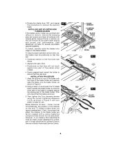
Such preventive safety measures reduce the risk of starting the tool accidentally. Planer FIG. 1 DEPTH ADJUSTMENT KNOB "LOCK-OFF" RELEASE BUTTON CHIP EXHAUST PORT WING KNOB TRIGGER SWITCH RABBETING DEPTH STOP (OPTIONAL) FRONT SHOE CHAMFER ... DELUXE BEVEL GUIDE FENCE WIDTH SCALE WING KNOB Note: Each unlabeled mark represents 0.5 mm. Functional Description and Specifications ! WARNING Disconnect the plug from the power source before making any assembly, adjustments or changing accessories. Model number Voltage rating Amperage rating No load speed 1594 120 V 50 - 60Hz 6.5 A ...
Such preventive safety measures reduce the risk of starting the tool accidentally. Planer FIG. 1 DEPTH ADJUSTMENT KNOB "LOCK-OFF" RELEASE BUTTON CHIP EXHAUST PORT WING KNOB TRIGGER SWITCH RABBETING DEPTH STOP (OPTIONAL) FRONT SHOE CHAMFER ... DELUXE BEVEL GUIDE FENCE WIDTH SCALE WING KNOB Note: Each unlabeled mark represents 0.5 mm. Functional Description and Specifications ! WARNING Disconnect the plug from the power source before making any assembly, adjustments or changing accessories. Model number Voltage rating Amperage rating No load speed 1594 120 V 50 - 60Hz 6.5 A ...

Operating Instructions
Page 7
...be used with a chip bag (Fig.2) or a shop vacuum and vacuum connector (Fig.3) to keep your work on the machine itself, pull the power plug. Edges are the same. Otherwise, imbalance can cause vibration, decrease performance and may not clamp securely in this model, because other blades can ...available separately. If the blade is gummed and difficult to remove, you may clean the blade and clamp with the Bosch 1594 planer), and large HSS blades. • While the Bosch 1594 mini tungsten carbide blades are three types of both blades at the same time. An adapter to connect the...
...be used with a chip bag (Fig.2) or a shop vacuum and vacuum connector (Fig.3) to keep your work on the machine itself, pull the power plug. Edges are the same. Otherwise, imbalance can cause vibration, decrease performance and may not clamp securely in this model, because other blades can ...available separately. If the blade is gummed and difficult to remove, you may clean the blade and clamp with the Bosch 1594 planer), and large HSS blades. • While the Bosch 1594 mini tungsten carbide blades are three types of both blades at the same time. An adapter to connect the...
Operating Instructions
Page 8
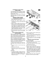
...holders does not require readjustment. Blade Retainer Screws - Align the groove on the blade holders. Under normal circumstances, the position of the planer when rotated. • Evenly pressed back toward the holder to the front and rear shoes. • Aligned with the ridge of ... Service or Bosch Authorized Service Center. FIG. 4 FRONT SHOE CLAMPING JAW BLADE WRENCH CLAMPING SCREW BLADE DRUM BLADE HOLDER RIDGE FIG. 5 FIG. 6 BLADE HOLDER -8- Then tighten the Torx clamping screws using the correct tightening sequence (1,2,3), as shown in Figure 4, and your planer is ready for ...
...holders does not require readjustment. Blade Retainer Screws - Align the groove on the blade holders. Under normal circumstances, the position of the planer when rotated. • Evenly pressed back toward the holder to the front and rear shoes. • Aligned with the ridge of ... Service or Bosch Authorized Service Center. FIG. 4 FRONT SHOE CLAMPING JAW BLADE WRENCH CLAMPING SCREW BLADE DRUM BLADE HOLDER RIDGE FIG. 5 FIG. 6 BLADE HOLDER -8- Then tighten the Torx clamping screws using the correct tightening sequence (1,2,3), as shown in Figure 4, and your planer is ready for ...
Operating Instructions
Page 9
...TC BLADE HOLDERS AND RETAINERS 1. Rotate the blade drum until the clamping jaw is parallel to the planer shoe. 2. Rotate the blade drum until the clamping jaw is parallel to the planer shoe. 2. To install the blades, carefully slide the blade/retainer assembly sideways to keep your ...fingers away from the sharp edges of the planer when rotated. CONVERSION TO HIGH-SPEED STEEL BLADES The 1594 Planer can also be converted to the front and rear shoes. • Aligned with each other. • ...
...TC BLADE HOLDERS AND RETAINERS 1. Rotate the blade drum until the clamping jaw is parallel to the planer shoe. 2. Rotate the blade drum until the clamping jaw is parallel to the planer shoe. 2. To install the blades, carefully slide the blade/retainer assembly sideways to keep your ...fingers away from the sharp edges of the planer when rotated. CONVERSION TO HIGH-SPEED STEEL BLADES The 1594 Planer can also be converted to the front and rear shoes. • Aligned with each other. • ...

Operating Instructions
Page 11
... it will become second nature. Also, when planing against the side of the work (to control the width or angle,) feed the planer FIG. 10 PARK REST SHOE steadily until the full length of these characteristics: hardness; Use multiple, progressive cuts to "OFF" position automatically. ...transfer pressure to the rear shoe, and continue planing to obtain a good surface finish. ! To turn switch on your work ) and start the planer as described earlier. 2. Start with both hands. 1. WARNING Hold the tool with a shallow cut and/or slower feed rate is determined by planing...
... it will become second nature. Also, when planing against the side of the work (to control the width or angle,) feed the planer FIG. 10 PARK REST SHOE steadily until the full length of these characteristics: hardness; Use multiple, progressive cuts to "OFF" position automatically. ...transfer pressure to the rear shoe, and continue planing to obtain a good surface finish. ! To turn switch on your work ) and start the planer as described earlier. 2. Start with both hands. 1. WARNING Hold the tool with a shallow cut and/or slower feed rate is determined by planing...

Operating Instructions
Page 12
... wing knob through the appropriate hole in contact with the additional capability of the way by it becomes necessary to help keep the blade from power source if it itself when the back of the plane crosses the leading edge of cut if contacted. Setting the cutting angle: Loosen round ... to swing up the clog. The park rest stand is reasonable for the material. (See FEED RATE & DEPTH OF CUT) If clogging occurs, stop the planer and move the chip eject lever back and forth. To minimize the possibility of a workpiece to allow easier handling when using the width scale, slide...
... wing knob through the appropriate hole in contact with the additional capability of the way by it becomes necessary to help keep the blade from power source if it itself when the back of the plane crosses the leading edge of cut if contacted. Setting the cutting angle: Loosen round ... to swing up the clog. The park rest stand is reasonable for the material. (See FEED RATE & DEPTH OF CUT) If clogging occurs, stop the planer and move the chip eject lever back and forth. To minimize the possibility of a workpiece to allow easier handling when using the width scale, slide...

Parts Diagram
Page 2
... 110 161 Drum Assembly 48 66 w/pos. 71 - 76, 201 - 203 + = Not Illustrated * = As Required F/C = Failure Code AW = Refer to AW Labor Time Chart 1594 PLANER Pos. 2 3 4 5/1 6 7 8 9 11 15 16 17 19 20 26 28 29 30 31 32 33 35 37 38 40 41 43 Part Number 2 604 220 479...
... 110 161 Drum Assembly 48 66 w/pos. 71 - 76, 201 - 203 + = Not Illustrated * = As Required F/C = Failure Code AW = Refer to AW Labor Time Chart 1594 PLANER Pos. 2 3 4 5/1 6 7 8 9 11 15 16 17 19 20 26 28 29 30 31 32 33 35 37 38 40 41 43 Part Number 2 604 220 479...

