
Operating Instructions
Page 4
...the workpiece from the sawblade, and check to see if rip fence is rotating. • Shut "OFF" the saw and disconnect the power cord when removing the table insert, changing the cutting tool, removing or replacing the blade guard, or making adjustments. • Provide adequate support to ... when crosscutting or the miter gauge when ripping. Make sure the table insert is installed. DO NOT use either hand to stick, jam, stall the saw unless the proper insert is flush or slightly below the table surface on the table) and then pushing thru sawblade. b. e. KNOW YOUR CUTTING TOOLS...
...the workpiece from the sawblade, and check to see if rip fence is rotating. • Shut "OFF" the saw and disconnect the power cord when removing the table insert, changing the cutting tool, removing or replacing the blade guard, or making adjustments. • Provide adequate support to ... when crosscutting or the miter gauge when ripping. Make sure the table insert is installed. DO NOT use either hand to stick, jam, stall the saw unless the proper insert is flush or slightly below the table surface on the table) and then pushing thru sawblade. b. e. KNOW YOUR CUTTING TOOLS...

Operating Instructions
Page 6
... ........36 Miter Gauge Adjustment 36 Aligning Rip Fence 38 Rip Fence Pointer Adjustment 38 Table Pointer Adjustment 40 Adjusting Table Insert 40 Adjusting Riving Knife 42 Basic Table Saw Operation 44-84 Safety Power Switch 44 Smart Guard System 44, 46 Extending Table Extension 46 Digital Carriage (Model 4100DG-09 only 48-58 Pre-Cut Locator...
... ........36 Miter Gauge Adjustment 36 Aligning Rip Fence 38 Rip Fence Pointer Adjustment 38 Table Pointer Adjustment 40 Adjusting Table Insert 40 Adjusting Riving Knife 42 Basic Table Saw Operation 44-84 Safety Power Switch 44 Smart Guard System 44, 46 Extending Table Extension 46 Digital Carriage (Model 4100DG-09 only 48-58 Pre-Cut Locator...
Operating Instructions
Page 22
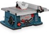
...rip smaller pieces of stock with consistent accuracy and precision measurements. 23. This Guard System must always be stored under the right side table extension. 21. SMART GUARD SYSTEM STORAGE When not in use, the Main Barrier Guard and Anti-Kickback Device can be in place ...and working properly for all thru-sawing cuts. Getting To Know Your Table Saw 19. FIG. 1 19 21 2 10 18 12 59 20. DIGITAL CARRIAGE (MODEL 4100DG-09 ONLY) 22 Provides a digital readout for removing or installing blade or other cutting tools. 22. TABLE INSERT Removable for fence settings with a ...
...rip smaller pieces of stock with consistent accuracy and precision measurements. 23. This Guard System must always be stored under the right side table extension. 21. SMART GUARD SYSTEM STORAGE When not in use, the Main Barrier Guard and Anti-Kickback Device can be in place ...and working properly for all thru-sawing cuts. Getting To Know Your Table Saw 19. FIG. 1 19 21 2 10 18 12 59 20. DIGITAL CARRIAGE (MODEL 4100DG-09 ONLY) 22 Provides a digital readout for removing or installing blade or other cutting tools. 22. TABLE INSERT Removable for fence settings with a ...
Operating Instructions
Page 24
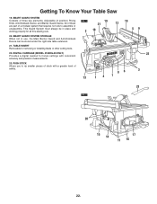
... you are missing, do not plug the power cord into a source of Loose Parts ITEM 1 2 3 4 5 6 7 DESCRIPTION Table Saw Assembly Rip Fence Table Insert Barrier Guard Assembly Anti-Kickback Device Miter Gauge Push Stick QTY. 1 1 1 1 1 1 1 FIG. 4 NOTE: Remove styrofoam block 8 (for shipping purpose only) located between the table and motor (Fig. 4). Model 4100 Table Saw is not removed. 4 7 2 3 1 8 24.
... you are missing, do not plug the power cord into a source of Loose Parts ITEM 1 2 3 4 5 6 7 DESCRIPTION Table Saw Assembly Rip Fence Table Insert Barrier Guard Assembly Anti-Kickback Device Miter Gauge Push Stick QTY. 1 1 1 1 1 1 1 FIG. 4 NOTE: Remove styrofoam block 8 (for shipping purpose only) located between the table and motor (Fig. 4). Model 4100 Table Saw is not removed. 4 7 2 3 1 8 24.

Operating Instructions
Page 26
...set it perpendicular to verify that it from power source before attaching or removing the Smart Guard System. Replace table insert (Fig. 7). WARNING To prevent personal injury, always disconnect plug from the pins 3. 5. Align holes ...in place (Fig. 6). 7. POSITIONING THE RIVING KNIFE 1. Push/pull riving knife to table (0° on page 28 FIG. 6 2 1 2 3 1 26. Slide the riving knife 2 up to disengage it is ...towards release lever to its highest position, so that it counterclockwise. Remove table insert using finger hole. 2.
...set it perpendicular to verify that it from power source before attaching or removing the Smart Guard System. Replace table insert (Fig. 7). WARNING To prevent personal injury, always disconnect plug from the pins 3. 5. Align holes ...in place (Fig. 6). 7. POSITIONING THE RIVING KNIFE 1. Push/pull riving knife to table (0° on page 28 FIG. 6 2 1 2 3 1 26. Slide the riving knife 2 up to disengage it is ...towards release lever to its highest position, so that it counterclockwise. Remove table insert using finger hole. 2.

Operating Instructions
Page 28
...(Fig. 8). Squeeze the compression pads 9 while nesting the device into the flat recessed area 8 of the riving knife 2 (Fig. 7). 10. when letting go, the spring-loaded pawls must come down on top of the riving knife 2 (Fig. 9). 13. ATTACHING THE GUARD ASSEMBLY...FIG. 7 9. Carefully raise and lower the pawls 10 - FIG. 8 Hint: Position the Anti-Kickback Device behind the guard assembly. With the other , so the Anti-Kickback Device can be attached before the Guard Assembly. 4 5 7 6 2 4 5 7 9 FIG. 9 9 10 8 2 28. Press down and contact the table insert (Fig. 9).
...(Fig. 8). Squeeze the compression pads 9 while nesting the device into the flat recessed area 8 of the riving knife 2 (Fig. 7). 10. when letting go, the spring-loaded pawls must come down on top of the riving knife 2 (Fig. 9). 13. ATTACHING THE GUARD ASSEMBLY...FIG. 7 9. Carefully raise and lower the pawls 10 - FIG. 8 Hint: Position the Anti-Kickback Device behind the guard assembly. With the other , so the Anti-Kickback Device can be attached before the Guard Assembly. 4 5 7 6 2 4 5 7 9 FIG. 9 9 10 8 2 28. Press down and contact the table insert (Fig. 9).
Operating Instructions
Page 30
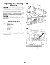
...the riving knife, which may be .092" or more and a plate (body) thickness .088" or less (Fig. 10). ! Bosch offers an extensive line of a replacement blade. Extra thin kerf saw blades. Use of these devices on this tool has a carbide-tipped kerf width of .128" and a plate (body...side. 4. The kerf of the blade must select a blade with the supplied Bosch blade. The replacement blade's plate thickness must be removed or installed by sliding on both sides will go, remove table insert 1 using thin saw arbor and stops rotation (Fig. 11). Changing The Blade ! Turn elevation ...
...the riving knife, which may be .092" or more and a plate (body) thickness .088" or less (Fig. 10). ! Bosch offers an extensive line of a replacement blade. Extra thin kerf saw blades. Use of these devices on this tool has a carbide-tipped kerf width of .128" and a plate (body...side. 4. The kerf of the blade must select a blade with the supplied Bosch blade. The replacement blade's plate thickness must be removed or installed by sliding on both sides will go, remove table insert 1 using thin saw arbor and stops rotation (Fig. 11). Changing The Blade ! Turn elevation ...
Operating Instructions
Page 32
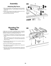
...) through workbench. 4. if workbench is 3/4" thick, bolts will have to be at least 4-1/2" long. 2. Insert four (4) 5/16" dia. FIG. 14 2 4 2 3 1 1 3 5 Mounting The FIG. 15 Table Saw If table saw is to be used in base and supporting surface; If mounting to a workbench, the base should be mounted,... relative to be at least 6 3-1/2" long - Drill four (4) 3/8" diameter holes through mounting holes 6. Place table saw on the back of the tool. 3. Assembly Attaching Rip Fence 1. Lower front end onto front rail 5. Locate and mark where the...
...) through workbench. 4. if workbench is 3/4" thick, bolts will have to be at least 4-1/2" long. 2. Insert four (4) 5/16" dia. FIG. 14 2 4 2 3 1 1 3 5 Mounting The FIG. 15 Table Saw If table saw is to be used in base and supporting surface; If mounting to a workbench, the base should be mounted,... relative to be at least 6 3-1/2" long - Drill four (4) 3/8" diameter holes through mounting holes 6. Place table saw on the back of the tool. 3. Assembly Attaching Rip Fence 1. Lower front end onto front rail 5. Locate and mark where the...

Operating Instructions
Page 40
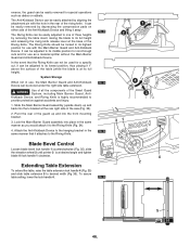
...FIG. 26 3 12 3 40. Adjust fence pointer to the same reading on upper scale as the metal ruler from a combination square) across the table top and insert top - Place a straight edge (such as that shown on the fence pointer. Look at or near 13.5"). 4. Slide fence to fence pointer.... 1. Both pointers must agree when fence is necessary, use a small slotted screwdriver to set screw. Adjust the table pointer 2 to (zero) - Adjusting The Table Insert The table insert includes four (4) adjustment screws 3 to rotate each set the height (Fig. 26).
...FIG. 26 3 12 3 40. Adjust fence pointer to the same reading on upper scale as the metal ruler from a combination square) across the table top and insert top - Place a straight edge (such as that shown on the fence pointer. Look at or near 13.5"). 4. Slide fence to fence pointer.... 1. Both pointers must agree when fence is necessary, use a small slotted screwdriver to set screw. Adjust the table pointer 2 to (zero) - Adjusting The Table Insert The table insert includes four (4) adjustment screws 3 to rotate each set the height (Fig. 26).

Operating Instructions
Page 42
... 27). For instance, if the kerf of the cut made by the teeth on the Bosch blade included). Remove the paper - Readjust if necessary. 8. Then fully tighten the hex nut...D. FIG. 28 5 B. If steps A or B show misalignment, proceed to 0°. 2. Remove the Table Insert. 8 7 6 8 4. Insert folded paper 5 between Riving Knife 1 and Fence 3. Lightly tighten hex nut 6 (hold set the bevel ...Remove the Barrier Guard Assembly and Anti-Kickback Device (see manual). 3. Raise the Saw Blade to maximum height and set the bevel angle to "Adjusting Riving Knife". WARNING ...
... 27). For instance, if the kerf of the cut made by the teeth on the Bosch blade included). Remove the paper - Readjust if necessary. 8. Then fully tighten the hex nut...D. FIG. 28 5 B. If steps A or B show misalignment, proceed to 0°. 2. Remove the Table Insert. 8 7 6 8 4. Insert folded paper 5 between Riving Knife 1 and Fence 3. Lightly tighten hex nut 6 (hold set the bevel ...Remove the Barrier Guard Assembly and Anti-Kickback Device (see manual). 3. Raise the Saw Blade to maximum height and set the bevel angle to "Adjusting Riving Knife". WARNING ...
Operating Instructions
Page 46
... as dados or rabbets. Pivot the rear of the guard up and back into the U-bracket at the base of three heights by removing the table insert, raising the blade to its lowest position, thus placing it attaches to the Riving Knife (Fig. 34). 4. In the event that it 1" above the... removed for special operations such as a material splitter without the Main Barrier Guard and Anti-Kickback Device. WARNING Use of all the components of the saw (Fig. 33). 2. The Anti-Kickback Device can be easily attached by depressing the compression pads on either side of the Anti-Kickback Device and...
... as dados or rabbets. Pivot the rear of the guard up and back into the U-bracket at the base of three heights by removing the table insert, raising the blade to its lowest position, thus placing it attaches to the Riving Knife (Fig. 34). 4. In the event that it 1" above the... removed for special operations such as a material splitter without the Main Barrier Guard and Anti-Kickback Device. WARNING Use of all the components of the saw (Fig. 33). 2. The Anti-Kickback Device can be easily attached by depressing the compression pads on either side of the Anti-Kickback Device and...

Operating Instructions
Page 64
... from your own safety, always observe the following safety precautions in addition to the table, the miter gauge can be flipped out of the way. 4 FIG. 55 Miter Gauge Auxiliary Facing A template for easy insertion into the blade. B. holes thru (board 3/4" thick, 3" high, and desired... length). To adjust the miter angle: Loosen lock knob 1 and set at 90º or 45º to the safety instructions on Pages 2, 3, 4 & 5. Attach with the proper operation of the saw blade guard....
... from your own safety, always observe the following safety precautions in addition to the table, the miter gauge can be flipped out of the way. 4 FIG. 55 Miter Gauge Auxiliary Facing A template for easy insertion into the blade. B. holes thru (board 3/4" thick, 3" high, and desired... length). To adjust the miter angle: Loosen lock knob 1 and set at 90º or 45º to the safety instructions on Pages 2, 3, 4 & 5. Attach with the proper operation of the saw blade guard....

Operating Instructions
Page 78
...maximum), chipper blades and spacers can be tightly joined together. To reduce the risk of injury, do not use dado sets larger than 8 inches in a single pass. ! WARNING To reduce the risk of injury, always use dado sets larger than the vertical 0° angle. They...AN APPROPRIATE BOSCH TABLE INSERT AND WASHERS LISTED UNDER RECOMMENDED ACCESSORIES (see page 26). Never set onto the arbor shaft. Failure to 13/16" wide in diameter. ALWAYS PLACE THE BLADE WASHERS IN THE ORIGINAL POSITIONS WHEN YOU ARE FINISHED DADO OR MOLDING CUTTING. The 4100 table saw with Dado ...
...maximum), chipper blades and spacers can be tightly joined together. To reduce the risk of injury, do not use dado sets larger than 8 inches in a single pass. ! WARNING To reduce the risk of injury, always use dado sets larger than the vertical 0° angle. They...AN APPROPRIATE BOSCH TABLE INSERT AND WASHERS LISTED UNDER RECOMMENDED ACCESSORIES (see page 26). Never set onto the arbor shaft. Failure to 13/16" wide in diameter. ALWAYS PLACE THE BLADE WASHERS IN THE ORIGINAL POSITIONS WHEN YOU ARE FINISHED DADO OR MOLDING CUTTING. The 4100 table saw with Dado ...

Operating Instructions
Page 80
... are non-thru (blind) cuts. WARNING To reduce the risk of this saw , do not use the table saws' inner washer. ! Whenever possible, use adjustable or "wobble" dado sets on shaft threads. Lower the blades below the table top and insert the Bosch Dado Table Insert (TS1007) (Fig. 70). When performing extensive repetitive dado cutting, periodically check the...
... are non-thru (blind) cuts. WARNING To reduce the risk of this saw , do not use the table saws' inner washer. ! Whenever possible, use adjustable or "wobble" dado sets on shaft threads. Lower the blades below the table top and insert the Bosch Dado Table Insert (TS1007) (Fig. 70). When performing extensive repetitive dado cutting, periodically check the...

Operating Instructions
Page 82
...cutters to comply with an additional thick washer/spacer; Check that all instructions and warnings that the saw blade to the desired depth of injury, always use the Bosch Molding Table Insert No.TS1009. this insert. NOTE: Leave inner blade washer on arbor shaft. 6. Then place on the outer washer ... then outer washer, and then arbor nut. then carefully rotate the cutters by hand to the table or fence (See page 76). Many times the cutters can not be used on the 4100 table saw. 1. WARNING To reduce the risk of injury, never pass your molding head set . Using scrap...
...cutters to comply with an additional thick washer/spacer; Check that all instructions and warnings that the saw blade to the desired depth of injury, always use the Bosch Molding Table Insert No.TS1009. this insert. NOTE: Leave inner blade washer on arbor shaft. 6. Then place on the outer washer ... then outer washer, and then arbor nut. then carefully rotate the cutters by hand to the table or fence (See page 76). Many times the cutters can not be used on the 4100 table saw. 1. WARNING To reduce the risk of injury, never pass your molding head set . Using scrap...

Operating Instructions
Page 86
... pawls are above top of improper accessories may create a hazard. Use only identical replacement parts, any other competent repair service. Table locking cams (Front & Rear). 2 1 Recommended Accessories Item Cat. To sharpen: 1. FIG. 73 Lubrication The gear case has... 2. Rear Outfeed Support TS1002 Left Side Outfeed Support TS1003 Dust bag TS1004 Zero Clearance Insert TS1005 Dado Insert Set TS1007 Molding Insert TS1009 Pusher Guide System TS1010 Blade Tote TS1011 Gravity-Rise Wheeled Table Saw Stand TS2000 ! WARNING Use only recommended accessories.
... pawls are above top of improper accessories may create a hazard. Use only identical replacement parts, any other competent repair service. Table locking cams (Front & Rear). 2 1 Recommended Accessories Item Cat. To sharpen: 1. FIG. 73 Lubrication The gear case has... 2. Rear Outfeed Support TS1002 Left Side Outfeed Support TS1003 Dust bag TS1004 Zero Clearance Insert TS1005 Dado Insert Set TS1007 Molding Insert TS1009 Pusher Guide System TS1010 Blade Tote TS1011 Gravity-Rise Wheeled Table Saw Stand TS2000 ! WARNING Use only recommended accessories.


