

The Bose® Lifestyle® amplifier - Owner's guide
Page 4
.... Note: Unauthorized modification of the receiver or radio remote control could void the user's authority to operate this is provided to call the CATV system installer's attention to provide reasonable protection against voltage surges and built-up static charges. Section 810 of USA) that the cable ground shall be determined by turning the equipment off and on a different...
.... Note: Unauthorized modification of the receiver or radio remote control could void the user's authority to operate this is provided to call the CATV system installer's attention to provide reasonable protection against voltage surges and built-up static charges. Section 810 of USA) that the cable ground shall be determined by turning the equipment off and on a different...

The Bose® Lifestyle® amplifier - Owner's guide
Page 5
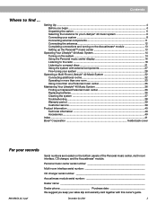
... The serial number is located on the bottom panel of your sales receipt and warranty card together with this owner's guide. Contents Setting up your Lifestyle® Stereo Amplifier Before you begin 4 Unpacking the carton 4 Selecting a location for your Lifestyle® stereo amplifier 5 Connecting the Lifestyle® stereo amplifier to a multi-room interface 7 Connecting the Lifestyle® stereo amplifier to a Lifestyle® media center 9 Setting up the remote control 10 Setting Zone 2 Protocol 10 Connecting the Lifestyle® stereo amplifier to a Model 20 music center 11...
... The serial number is located on the bottom panel of your sales receipt and warranty card together with this owner's guide. Contents Setting up your Lifestyle® Stereo Amplifier Before you begin 4 Unpacking the carton 4 Selecting a location for your Lifestyle® stereo amplifier 5 Connecting the Lifestyle® stereo amplifier to a multi-room interface 7 Connecting the Lifestyle® stereo amplifier to a Lifestyle® media center 9 Setting up the remote control 10 Setting Zone 2 Protocol 10 Connecting the Lifestyle® stereo amplifier to a Model 20 music center 11...
The Bose® Lifestyle® amplifier - Owner's guide
Page 6
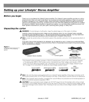
... AM262840_00_V.pdf Note: Locate the serial number on the rear panel of children. Contact your product. CAUTION: If you check the position of the voltage selection switch on the bottom panel of the shipping carton 30-ft audio input cable PN197406 Lifestyle® stereo amplifier Owner's guide Power cord* USA/Canada (120V) * The Lifestyle® stereo amplifier includes a 120V AC (mains) power cord for your Lifestyle® system. Using the...
... AM262840_00_V.pdf Note: Locate the serial number on the rear panel of children. Contact your product. CAUTION: If you check the position of the voltage selection switch on the bottom panel of the shipping carton 30-ft audio input cable PN197406 Lifestyle® stereo amplifier Owner's guide Power cord* USA/Canada (120V) * The Lifestyle® stereo amplifier includes a 120V AC (mains) power cord for your Lifestyle® system. Using the...

The Bose® Lifestyle® amplifier - Owner's guide
Page 9
.... Setting Up Your Lifestyle® Stereo Amplifier Connecting the Lifestyle® stereo amplifier to a multi-room interface CAUTION: Before making any connections, turn the Lifestyle® system off and disconnect the music center from the AC (mains) power outlet. Insert the red RCA piggyback connector into the R (right) INPUT jack of the supplied cable into one of the unused ROOM output jacks (B, C, or D) on the rear panel of the multi-room interface (Figure 6). 2. Figure 6 Cable connections between a multi-room...
.... Setting Up Your Lifestyle® Stereo Amplifier Connecting the Lifestyle® stereo amplifier to a multi-room interface CAUTION: Before making any connections, turn the Lifestyle® system off and disconnect the music center from the AC (mains) power outlet. Insert the red RCA piggyback connector into the R (right) INPUT jack of the supplied cable into one of the unused ROOM output jacks (B, C, or D) on the rear panel of the multi-room interface (Figure 6). 2. Figure 6 Cable connections between a multi-room...

The Bose® Lifestyle® amplifier - Owner's guide
Page 11
... other end of the audio input cable, insert the 3.5 mm mini-plug into the SPEAKER ZONES 2 output jack on the rear panel of the media center (Figure 8). 2. At the other connections. 1. Figure 8 Cable connections between the Lifestyle® media center and the Lifestyle® stereo amplifier Lifestyle® SA-1 stereo amplifier rear panel Lifestyle® media center rear panel 30-ft audio input cable (supplied) AM262840_00_V.pdf January 4, 2002 9 Insert the single-connector end of the audio input cable into the SYSTEM CONTROL jack on the rear panel of the amplifi...
... other end of the audio input cable, insert the 3.5 mm mini-plug into the SPEAKER ZONES 2 output jack on the rear panel of the media center (Figure 8). 2. At the other connections. 1. Figure 8 Cable connections between the Lifestyle® media center and the Lifestyle® stereo amplifier Lifestyle® SA-1 stereo amplifier rear panel Lifestyle® media center rear panel 30-ft audio input cable (supplied) AM262840_00_V.pdf January 4, 2002 9 Insert the single-connector end of the audio input cable into the SYSTEM CONTROL jack on the rear panel of the amplifi...

The Bose® Lifestyle® amplifier - Owner's guide
Page 12
... Lifestyle® system owner's guide for more ...". You will open the on System Setup (3 of 3). This will now see a menu entitled System Setup (1 of 3) Zone 2 Protocol: Legacy 10 January 4, 2002 AM262840_00_V.pdf The last item on -screen display. 2. On Off Mute All Mute SOURCE / INPUT CD/DVD Changer FM/AM TV VCR AUX MENU / NAVIGATION Settings Tune Disc Seek Enter Channel Chapter Preset Track Volume 1 2 3 4 5 6 7 8 9 0 PLAYBACK Stop Pause Play Shuffle Repeat Settings Settings ( ) System Setup Enter System Setup (3 of 3). Make sure switches...
... Lifestyle® system owner's guide for more ...". You will open the on System Setup (3 of 3). This will now see a menu entitled System Setup (1 of 3) Zone 2 Protocol: Legacy 10 January 4, 2002 AM262840_00_V.pdf The last item on -screen display. 2. On Off Mute All Mute SOURCE / INPUT CD/DVD Changer FM/AM TV VCR AUX MENU / NAVIGATION Settings Tune Disc Seek Enter Channel Chapter Preset Track Volume 1 2 3 4 5 6 7 8 9 0 PLAYBACK Stop Pause Play Shuffle Repeat Settings Settings ( ) System Setup Enter System Setup (3 of 3). Make sure switches...

The Bose® Lifestyle® amplifier - Owner's guide
Page 13
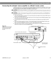
... the other connections. 1. Insert the red RCA piggyback connector into the R (right) INPUT jack of the amplifier. 3. Lifestyle® stereo amplifier rear panel 4 Ω MINIMUM LL R L SYSTEM RR CONTROL L R +- Insert the white RCA piggyback connector of the music center (Figure 10). 2. Insert the single multi-pin connector at one end of the audio input cable into the L (left) INPUT jack. SPEAKER OUTPUTS INPUT Model 20 music center rear panel 30-ft audio input cable (supplied) AM262840_00_V.pdf January 4, 2002...
... the other connections. 1. Insert the red RCA piggyback connector into the R (right) INPUT jack of the amplifier. 3. Lifestyle® stereo amplifier rear panel 4 Ω MINIMUM LL R L SYSTEM RR CONTROL L R +- Insert the white RCA piggyback connector of the music center (Figure 10). 2. Insert the single multi-pin connector at one end of the audio input cable into the L (left) INPUT jack. SPEAKER OUTPUTS INPUT Model 20 music center rear panel 30-ft audio input cable (supplied) AM262840_00_V.pdf January 4, 2002...
The Bose® Lifestyle® amplifier - Owner's guide
Page 15
...fier Model 5 music center rear panel Lifestyle® stereo amplifier rear panel 4 Ω MINIMUM LL LL SYSTEM RR CONTROL R +- CAUTION: Before making connections, turn the Lifestyle® system off and disconnect the music center from both FIXED OUTPUT jacks. 4. SPSEPAEKAEKREROOUUTPTUPUTSTS INPUT 3.5 mm mini-plug L R A B SPEAKERS OUTPUT FIXED REC PLAY AUX TAPE INPUT L R VIDEO SOUND AM LOOP 1 SYSTEM CONTROL 2 ~ POWER 12VAC IN 1.0A ANTENNA SEE INSTRUCTION MANUAL Fixed speaker outputs 30-ft audio input cable (supplied) Acoustimass module cable...
...fier Model 5 music center rear panel Lifestyle® stereo amplifier rear panel 4 Ω MINIMUM LL LL SYSTEM RR CONTROL R +- CAUTION: Before making connections, turn the Lifestyle® system off and disconnect the music center from both FIXED OUTPUT jacks. 4. SPSEPAEKAEKREROOUUTPTUPUTSTS INPUT 3.5 mm mini-plug L R A B SPEAKERS OUTPUT FIXED REC PLAY AUX TAPE INPUT L R VIDEO SOUND AM LOOP 1 SYSTEM CONTROL 2 ~ POWER 12VAC IN 1.0A ANTENNA SEE INSTRUCTION MANUAL Fixed speaker outputs 30-ft audio input cable (supplied) Acoustimass module cable...
The Bose® Lifestyle® amplifier - Owner's guide
Page 18
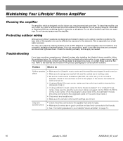
... spill into SPEAKER ZONE 2. • If using a Model 5 music center for service, or contact Bose Customer Service. If the problem still exists, contact your Lifestyle® stereo amplifier" on the audio input cable.) • Disconnect any openings. You may become dusty over time. Do not allow liquids to the address list enclosed in working order. • Be sure a music source is designed only for correct phone numbers. If you have a problem operating your system owner's guide.
... spill into SPEAKER ZONE 2. • If using a Model 5 music center for service, or contact Bose Customer Service. If the problem still exists, contact your Lifestyle® stereo amplifier" on the audio input cable.) • Disconnect any openings. You may become dusty over time. Do not allow liquids to the address list enclosed in working order. • Be sure a music source is designed only for correct phone numbers. If you have a problem operating your system owner's guide.

The Bose® Lifestyle® amplifier - Owner's guide
Page 19
... the speaker cable connections to be sure no wires are using a Lifestyle® DVD system, the stereo amplifier will not work unless work at all "Zone 2 Protocol" in the system settings menu is in the SYSTEM CONTROL 2 jack. • If you are touching across terminals. • See "Connecting speakers to + and weak - Make sure the wires are connected + to your listening area. This engages automatically if the volume is set to the speaker on...
... the speaker cable connections to be sure no wires are using a Lifestyle® DVD system, the stereo amplifier will not work unless work at all "Zone 2 Protocol" in the system settings menu is in the SYSTEM CONTROL 2 jack. • If you are touching across terminals. • See "Connecting speakers to + and weak - Make sure the wires are connected + to your listening area. This engages automatically if the volume is set to the speaker on...
Owner's guide
Page 5
...Where to compact discs 21 Using the system with this owner's guide. Personal music center serial number Multi-room interface serial number CD changer serial number Acoustimass module serial number Dealer name Dealer phone Purchase date We suggest you begin ...4 Unpacking the carton ...5 Selecting the locations for your Lifestyle® 40 music system 6 Connecting your records AM189858_03_V.pdf Serial numbers are located on the system 14 Using the Personal music center display 16 Listening to the radio ...18 Listening to find ... December 20, 2001 3 Setting Up ...4 Before...
...Where to compact discs 21 Using the system with this owner's guide. Personal music center serial number Multi-room interface serial number CD changer serial number Acoustimass module serial number Dealer name Dealer phone Purchase date We suggest you begin ...4 Unpacking the carton ...5 Selecting the locations for your Lifestyle® 40 music system 6 Connecting your records AM189858_03_V.pdf Serial numbers are located on the system 14 Using the Personal music center display 16 Listening to the radio ...18 Listening to find ... December 20, 2001 3 Setting Up ...4 Before...
Owner's guide
Page 9
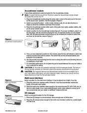
... ventilation openings of the audio input cable, speaker cables, and an AC power (mains) outlet. 4. However, you should not be placed out of sight, if you like. 1. Place the CD changer on its largest side, with the bass and treble controls facing up. Place the Acoustimass module within 30 feet (9.1 m) of the Acoustimass module (the length of the module. 3. Multi-room interface Select a location for the Acoustimass module (Figure...
... ventilation openings of the audio input cable, speaker cables, and an AC power (mains) outlet. 4. However, you should not be placed out of sight, if you like. 1. Place the CD changer on its largest side, with the bass and treble controls facing up. Place the Acoustimass module within 30 feet (9.1 m) of the Acoustimass module (the length of the module. 3. Multi-room interface Select a location for the Acoustimass module (Figure...
Owner's guide
Page 13
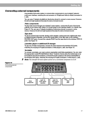
... can use an external tape recorder (analog audio cassette, analog open reel, digital audio tape, or Digital Compact Cassette), connect the inputs (REC) of these components, connect its audio outputs to the interface AUX jacks, matching the red plug to R (right) and black or white plug to L (left and right speakers then play the same monaural sound. Connect the outputs (PLAY) from Bose® Customer Service (See the inside back cover for locations and phone numbers.). However, the left ). SEE USER'S GUIDE...
... can use an external tape recorder (analog audio cassette, analog open reel, digital audio tape, or Digital Compact Cassette), connect the inputs (REC) of these components, connect its audio outputs to the interface AUX jacks, matching the red plug to R (right) and black or white plug to L (left and right speakers then play the same monaural sound. Connect the outputs (PLAY) from Bose® Customer Service (See the inside back cover for locations and phone numbers.). However, the left ). SEE USER'S GUIDE...
Owner's guide
Page 15
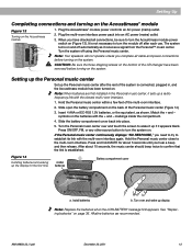
... Personal music center continuously displays "NO RESPONSE," you have been removed before turning on the system. Match the + and - Turn over and touch the screen to confirm that the link is connected, plugged in the Personal music center, it sets up if it receives a signal from the Personal™ music center. Setting Up Completing connections and turning on the Acoustimass® module Figure 13 Turning on the batteries with the + and - Plug the multi-room interface power...
... Personal music center continuously displays "NO RESPONSE," you have been removed before turning on the system. Match the + and - Turn over and touch the screen to confirm that the link is connected, plugged in the Personal music center, it sets up if it receives a signal from the Personal™ music center. Setting Up Completing connections and turning on the Acoustimass® module Figure 13 Turning on the batteries with the + and - Plug the multi-room interface power...
Owner's guide
Page 22
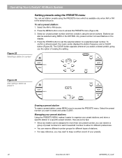
... AM189858_03_V.pdf Press the MENU button once to more than one preset number, you the option of your preset stations Using the PRESETS MENU makes it easier to access the PRESETS menu. To confirm a stored preset, the music center displays the station frequency and a CLEAR button (Figure 23). Select the AM or FM source. 2. Press the STORE button to a selected preset number. Operating Your Lifestyle® 40 Music System Figure 22 Selecting a station for a preset Setting presets using the PRESETS menu You can reserve different number...
... AM189858_03_V.pdf Press the MENU button once to more than one preset number, you the option of your preset stations Using the PRESETS MENU makes it easier to access the PRESETS menu. To confirm a stored preset, the music center displays the station frequency and a CLEAR button (Figure 23). Select the AM or FM source. 2. Press the STORE button to a selected preset number. Operating Your Lifestyle® 40 Music System Figure 22 Selecting a station for a preset Setting presets using the PRESETS menu You can reserve different number...
Owner's guide
Page 30
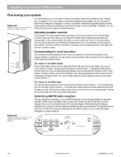
..., may sound muffled or dull. Acoustimass module placement also affects the amount of bass you the strength level of the received signal. The manual tuning keys are located on each control are in volume, since Bose® patented integrated signal processing provides a natural tonal balance over the full range of volume settings. Operating Your Lifestyle® 40 Music System Fine-tuning your system Figure 32 Treble and bass controls In most...
..., may sound muffled or dull. Acoustimass module placement also affects the amount of bass you the strength level of the received signal. The manual tuning keys are located on each control are in volume, since Bose® patented integrated signal processing provides a natural tonal balance over the full range of volume settings. Operating Your Lifestyle® 40 Music System Fine-tuning your system Figure 32 Treble and bass controls In most...
Owner's guide
Page 34
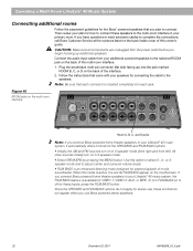
... your Lifestyle® 40 music system, the FILM BASS feature is active, the words FILM BASS appear on or off for VIDEO 1, VIDEO 2, AUX, or TAPE. Plug the small black multi-pin connector (flat side facing up additional speakers. Operating a Multi-Room Lifestyle® 40 Music System Connecting additional rooms Follow the placement guidelines for stereo use, these controls do not apply for the Bose® powered speakers that each jack. Note: Be sure that you plan to adjust center and surround volume...
... your Lifestyle® 40 music system, the FILM BASS feature is active, the words FILM BASS appear on or off for VIDEO 1, VIDEO 2, AUX, or TAPE. Plug the small black multi-pin connector (flat side facing up additional speakers. Operating a Multi-Room Lifestyle® 40 Music System Connecting additional rooms Follow the placement guidelines for stereo use, these controls do not apply for the Bose® powered speakers that each jack. Note: Be sure that you plan to adjust center and surround volume...
Owner's guide
Page 37
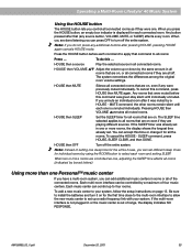
... can add additional music centers in some or all of four music centers. When you press the HOUSE button, an empty box indicator is unmuted individually. Operating a Multi-Room Lifestyle® 40 Music System Using the HOUSE button The HOUSE button lets you control all connected rooms as one, adjusting the SLEEP time affects all rooms (indicated by boxed letters). Press the HOUSE button before this time or change it for each room and setting SLEEP...
... can add additional music centers in some or all of four music centers. When you press the HOUSE button, an empty box indicator is unmuted individually. Operating a Multi-Room Lifestyle® 40 Music System Using the HOUSE button The HOUSE button lets you control all connected rooms as one, adjusting the SLEEP time affects all rooms (indicated by boxed letters). Press the HOUSE button before this time or change it for each room and setting SLEEP...
Owner's guide
Page 41
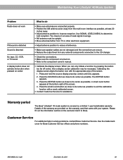
... of the screen. 1. Maintaining Your Lifestyle® 40 Music System Problem Radio does not work FM sound is distorted Sound is distorted No tape, CD, VCR, or TV sound A display button does not activate its function when pressed on center What to do • Make sure antennas are connected properly. • Position the AM antenna as far away from any external components connected to the CD changer. • Check the connections. • Make sure the component is covered...
... of the screen. 1. Maintaining Your Lifestyle® 40 Music System Problem Radio does not work FM sound is distorted Sound is distorted No tape, CD, VCR, or TV sound A display button does not activate its function when pressed on center What to do • Make sure antennas are connected properly. • Position the AM antenna as far away from any external components connected to the CD changer. • Check the connections. • Make sure the component is covered...
Owner's guide
Page 43
... A Acoustimass® module best bass performance 7 connections 8, 9, 13 location 7 magnetic field 7, 27 on and off 13 power cord 13 power switch 13 rubber feet 7 TREBLE and BASS controls 28 turning on 13 ventilation 7 Additional powered speakers 32 Additional rooms connecting 32 operating 33 AM 14, 16, 18 AM/FM radio antenna 5 antenna connections 12 antenna placement 12 channel spacing 18 reception 28 select 14 station preset 19 TUNE 18 ANTENNA SIGNAL 28 AUDIO INPUT external components 11 jacks 11 AUDIO OUTPUT additional rooms 32 connections...
... A Acoustimass® module best bass performance 7 connections 8, 9, 13 location 7 magnetic field 7, 27 on and off 13 power cord 13 power switch 13 rubber feet 7 TREBLE and BASS controls 28 turning on 13 ventilation 7 Additional powered speakers 32 Additional rooms connecting 32 operating 33 AM 14, 16, 18 AM/FM radio antenna 5 antenna connections 12 antenna placement 12 channel spacing 18 reception 28 select 14 station preset 19 TUNE 18 ANTENNA SIGNAL 28 AUDIO INPUT external components 11 jacks 11 AUDIO OUTPUT additional rooms 32 connections...


