Owners Guide
Page 5
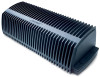
... stereo amplifier 20 Powering-up your system 21 Setting Up Additional Rooms For Sound 22 Setup guidelines for additional rooms 22 Setting up remote controls for other rooms 23 Setting up the amplifier room code 24 Setting Up Advanced Features 25 Amplifier mode switches 25 Stereo ...service 27 Limited warranty 27 Accessories 27 Technical information 28 For your product registration card together with this owner's guide. 3 Model: SA2 SA3 Serial number Purchase date We suggest you begin 4 Unpacking the carton 4 Connection panel features 5 Setting Up Your Lifestyle® Stereo ...
... stereo amplifier 20 Powering-up your system 21 Setting Up Additional Rooms For Sound 22 Setup guidelines for additional rooms 22 Setting up remote controls for other rooms 23 Setting up the amplifier room code 24 Setting Up Advanced Features 25 Amplifier mode switches 25 Stereo ...service 27 Limited warranty 27 Accessories 27 Technical information 28 For your product registration card together with this owner's guide. 3 Model: SA2 SA3 Serial number Purchase date We suggest you begin 4 Unpacking the carton 4 Connection panel features 5 Setting Up Your Lifestyle® Stereo ...
Owners Guide
Page 7
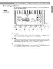
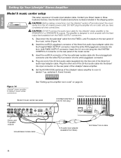
Contact your Bose® dealer or call Bose Customer Service for information on installing this guide. 3 SPEAKER OUTPUTS Left and right amplifier speaker outputs. See the contact list inside the back cover of ..." on this product. English Introducing the Lifestyle® SA-2 and SA-3 Stereo Amplifier Connection panel features The connection panel includes the input/output connections plus room code switches and amplifier LED status indicators. Figure 2 Lifestyle® amplifier connection panel 1 2 3 4 5 6 7 1 AC POWER AC power cord connector. There is no on/off switch on...
Contact your Bose® dealer or call Bose Customer Service for information on installing this guide. 3 SPEAKER OUTPUTS Left and right amplifier speaker outputs. See the contact list inside the back cover of ..." on this product. English Introducing the Lifestyle® SA-2 and SA-3 Stereo Amplifier Connection panel features The connection panel includes the input/output connections plus room code switches and amplifier LED status indicators. Figure 2 Lifestyle® amplifier connection panel 1 2 3 4 5 6 7 1 AC POWER AC power cord connector. There is no on/off switch on...
Owners Guide
Page 8
...page 25. English Introducing the Lifestyle® SA-2 and SA-3 Stereo Amplifier ROOM CODE switches 4 Microswitches for connecting the amplifier to allow daisy chaining. 6 SA-3 For switches 6 through to the output connector to a Bose® link network. Input signals are passed through 9, see "Setting Up ..." on page 21. 6 AUX INPUT (SA-3 only) Left and right channel line inputs for a local audio device. 7 Bose® link INPUT/OUTPUT Nine-pin DIN connectors used for setting room code and amplifier advanced features. See "Powering-up the amplifier room code" on page 24.
...page 25. English Introducing the Lifestyle® SA-2 and SA-3 Stereo Amplifier ROOM CODE switches 4 Microswitches for connecting the amplifier to allow daisy chaining. 6 SA-3 For switches 6 through to the output connector to a Bose® link network. Input signals are passed through 9, see "Setting Up ..." on page 21. 6 AUX INPUT (SA-3 only) Left and right channel line inputs for a local audio device. 7 Bose® link INPUT/OUTPUT Nine-pin DIN connectors used for setting room code and amplifier advanced features. See "Powering-up the amplifier room code" on page 24.
Owners Guide
Page 13
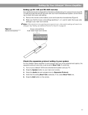
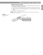
...4) match the house code settings in your system For the Lifestyle® stereo amplifier to work with your home entertainment system, the expansion protocol menu item must be set up for a second room (room B). Make sure that the setting Bose® link is selected. If not, select Bose® link now....tab and navigate down to be changed. Note: If this remote is shipped from the factory already set to Bose® link. See "Setting Up Additional Rooms For Sound" on the remote. 11 English Figure 6 Remote microswitches Setting Up Your Lifestyle® Stereo Amplifier ...
...4) match the house code settings in your system For the Lifestyle® stereo amplifier to work with your home entertainment system, the expansion protocol menu item must be set up for a second room (room B). Make sure that the setting Bose® link is selected. If not, select Bose® link now....tab and navigate down to be changed. Note: If this remote is shipped from the factory already set to Bose® link. See "Setting Up Additional Rooms For Sound" on the remote. 11 English Figure 6 Remote microswitches Setting Up Your Lifestyle® Stereo Amplifier ...
Owners Guide
Page 15
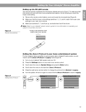
... Your second remote is reset to Legacy. 13 Remove the remote control battery cover and locate the microswitches (Figure 8). 2. House code switches must match main room remote ON Figure 9 Setting Zone 2 Protocol Setting the Zone 2 Protocol in your home entertainment system For the Lifestyle® stereo...Lifestyle® media center, you will need to set up for more than one room. Scroll down . Make sure switches 5, 7, and 8 are up, and switches 6 and 9 are down the menu to check the house code setting. 1. Turn on operating your home entertainment system, do the following to ...
... Your second remote is reset to Legacy. 13 Remove the remote control battery cover and locate the microswitches (Figure 8). 2. House code switches must match main room remote ON Figure 9 Setting Zone 2 Protocol Setting the Zone 2 Protocol in your home entertainment system For the Lifestyle® stereo...Lifestyle® media center, you will need to set up for more than one room. Scroll down . Make sure switches 5, 7, and 8 are up, and switches 6 and 9 are down the menu to check the house code setting. 1. Turn on operating your home entertainment system, do the following to ...
Owners Guide
Page 18
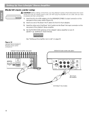
... See "Setting up , switches 6, 8 and 9 down). Figure 12 Lifestyle® stereo amplifier to -9-pin DIN adapter 20-ft Bose® link A cable 16 Set the ROOM CODE switches of the Lifestyle® stereo amplifier to -9-in DIN adapter into the SPEAKER ZONES 2 output connector on the rear panel of... the music center (Figure 12). 2. Insert the 8-to room E (switch 7 up the amplifier room code" on the rear panel of the Bose® link A cable into an outlet until you have ® completed all other end of the...
... See "Setting up , switches 6, 8 and 9 down). Figure 12 Lifestyle® stereo amplifier to -9-pin DIN adapter 20-ft Bose® link A cable 16 Set the ROOM CODE switches of the Lifestyle® stereo amplifier to -9-in DIN adapter into the SPEAKER ZONES 2 output connector on the rear panel of... the music center (Figure 12). 2. Insert the 8-to room E (switch 7 up the amplifier room code" on the rear panel of the Bose® link A cable into an outlet until you have ® completed all other end of the...
Owners Guide
Page 19
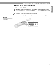
... Figure 13 RC-20 remote Zone 2 switch settings Setting Up Your Lifestyle® Stereo Amplifier Setting up the RC-20 remote for more than one room. 17 Remove the remote control battery cover and locate the miniature switches (Figure 13). 2. Make sure that the house...
... Figure 13 RC-20 remote Zone 2 switch settings Setting Up Your Lifestyle® Stereo Amplifier Setting up the RC-20 remote for more than one room. 17 Remove the remote control battery cover and locate the miniature switches (Figure 13). 2. Make sure that the house...
Owners Guide
Page 20
... L (left) FIXED OUTPUT connector. Insert the white RCA piggyback connector into the Bose® link input connector on page 24. Contact your Bose® dealer or Bose Customer Service. CAUTION: DO NOT connect the audio input cable for the Lifestyle®...room E (switch 7 up, switches 6, 8 and 9 down). Plug the other connections. Set the ROOM CODE switches of the Lifestyle® stereo amplifier. 5. See "Setting up the amplifier room code" on the rear panel of the Lifestyle® stereo amplifier to work properly with the fixed output level available from Bose) 20-ft Bose...
... L (left) FIXED OUTPUT connector. Insert the white RCA piggyback connector into the Bose® link input connector on page 24. Contact your Bose® dealer or Bose Customer Service. CAUTION: DO NOT connect the audio input cable for the Lifestyle®...room E (switch 7 up, switches 6, 8 and 9 down). Plug the other connections. Set the ROOM CODE switches of the Lifestyle® stereo amplifier. 5. See "Setting up the amplifier room code" on the rear panel of the Lifestyle® stereo amplifier to work properly with the fixed output level available from Bose) 20-ft Bose...
Owners Guide
Page 21
... on ). Slide switch 5 down (off) and 6 up a second RC-5 remote control to your first remote. 3. Make sure that the house code settings (switches 1, 2, 3, and 4) match those in more than one room. 19 Note: Refer to operate your Lifestyle® stereo amplifier. 1. Remove the remote control battery cover and locate the miniature switches...
... on ). Slide switch 5 down (off) and 6 up a second RC-5 remote control to your first remote. 3. Make sure that the house code settings (switches 1, 2, 3, and 4) match those in more than one room. 19 Note: Refer to operate your Lifestyle® stereo amplifier. 1. Remove the remote control battery cover and locate the miniature switches...

Owners Guide
Page 23
... up as a supplemental amplifier and it is ON. 21 The status LED tells you the operational status of Lifestyle® stereo amplifier AC power cord ROOM CODE Status LED LED activity Constant slow blinking (1 sec. Figure 17 Connecting the power cord Rear panel of the amplifier. 3. Using the power cord included with... the small connector on one end of the amplifier (Figure 17). 2. The amplifier is ON and receiving data commands from the media center through the Bose® link port.
... up as a supplemental amplifier and it is ON. 21 The status LED tells you the operational status of Lifestyle® stereo amplifier AC power cord ROOM CODE Status LED LED activity Constant slow blinking (1 sec. Figure 17 Connecting the power cord Rear panel of the amplifier. 3. Using the power cord included with... the small connector on one end of the amplifier (Figure 17). 2. The amplifier is ON and receiving data commands from the media center through the Bose® link port.
Owners Guide
Page 24
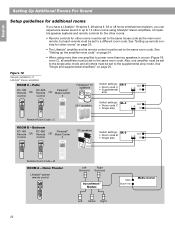
... Channel Volume Seek Shuffle Repeat 1 2 3 4 5 6 7 8 9 Info Last 0 251® speakers Switch settings: SA-3 • Room code C • Single amp OUT L R IN Remote Room Code = C ROOM B - Home Theater Lifestyle® system remote control Left Right Surround Surround Acoustimass® Module Main Bose® link Media Center Left Center Right 22 Bedroom RC-18S RC-38S Remote OR...
... Channel Volume Seek Shuffle Repeat 1 2 3 4 5 6 7 8 9 Info Last 0 251® speakers Switch settings: SA-3 • Room code C • Single amp OUT L R IN Remote Room Code = C ROOM B - Home Theater Lifestyle® system remote control Left Right Surround Surround Acoustimass® Module Main Bose® link Media Center Left Center Right 22 Bedroom RC-18S RC-38S Remote OR...
Owners Guide
Page 25
... set up the RC-18S or RC-38S remote: 1. Note: Refer to your main room remote. 3. Make sure that the house code settings (switches 1, 2, 3, and 4) match the house code settings in more than one room. Remove the remote control battery cover and locate the microswitches (Figure 19). 2. Figure 19 ON...-18S or RC-38S remote To set up the Personal® music center II: Refer to the same room code as set for room B. This remote is used beyond a second room, set switches 6, 7, 8, and 9 to the owner's guide included with the Personal® music center II for instructions on operating...
... set up the RC-18S or RC-38S remote: 1. Note: Refer to your main room remote. 3. Make sure that the house code settings (switches 1, 2, 3, and 4) match the house code settings in more than one room. Remove the remote control battery cover and locate the microswitches (Figure 19). 2. Figure 19 ON...-18S or RC-38S remote To set up the Personal® music center II: Refer to the same room code as set for room B. This remote is used beyond a second room, set switches 6, 7, 8, and 9 to the owner's guide included with the Personal® music center II for instructions on operating...

Owners Guide
Page 26
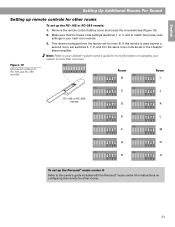
English Setting Up Additional Rooms For Sound Setting up the amplifier room code The room code of the amplifier must match the room code of the remote used in the room where the speakers are installed. Figure 20 Amplifier room code settings Room code switches SA-3 SA-2 Room B ABC 6 7 8 9 Room I ABC 6 7 8 9 C ABC 6 7 8 9 J ABC 6 7 8 9 D ABC 6 7 8 9 K ABC 6 7 8 9 E ABC 6 7 8 9 L ABC 6 7 8 9 F ABC 6 7 8 9 M ABC 6 7 8 9 G ABC 6 7 8 9 N ABC 6 7 8 9 H ABC 6 7 8 9 O ABC 6 7 8 9 24
English Setting Up Additional Rooms For Sound Setting up the amplifier room code The room code of the amplifier must match the room code of the remote used in the room where the speakers are installed. Figure 20 Amplifier room code settings Room code switches SA-3 SA-2 Room B ABC 6 7 8 9 Room I ABC 6 7 8 9 C ABC 6 7 8 9 J ABC 6 7 8 9 D ABC 6 7 8 9 K ABC 6 7 8 9 E ABC 6 7 8 9 L ABC 6 7 8 9 F ABC 6 7 8 9 M ABC 6 7 8 9 G ABC 6 7 8 9 N ABC 6 7 8 9 H ABC 6 7 8 9 O ABC 6 7 8 9 24

Owners Guide
Page 27
...shipped with this feature turned off , change their volumes, or mute them all on , thereby automatically switching the amplifier from standby to the same room code as an outdoor patio, requiring more than one amplifier and set switch C up - English Setting Up Advanced Features Amplifier mode switches The advanced features...only) The output of the SA-3 amplifier can be set to stereo (switch A up (supplemental amp mode) on all other amplifiers. • Set the room code in the remote control. • Now, you can turn them together using microswitches A, B, and C (Figure 21).
...shipped with this feature turned off , change their volumes, or mute them all on , thereby automatically switching the amplifier from standby to the same room code as an outdoor patio, requiring more than one amplifier and set switch C up - English Setting Up Advanced Features Amplifier mode switches The advanced features...only) The output of the SA-3 amplifier can be set to stereo (switch A up (supplemental amp mode) on all other amplifiers. • Set the room code in the remote control. • Now, you can turn them together using microswitches A, B, and C (Figure 21).