
User Manual in English
Page 1
...page CONTENTS 2 Introduction 2 What is included? 3 Features 3 About 2 Ohm operation 4 General precautions 4 Installation precautions 4 Mounting the amplifier 5 Connecting the amplifier 6 Low level input wiring 9 High level input wiring 10 2CH Power and Speaker wiring 2CH and Bridged Modes 11 2CH Power and Speaker wiring TriMode 12 4CH Power and Speaker wiring 4CH and Bridged Modes 13 4CH Power and Speaker wiring TriMode 14 MonoBlock Power and Speaker wiring 15 Troubleshooting 16 Specifications PHANTOM MOSFET Amplifier User's Manual - It has been designed, engineered and manufactured to...
...page CONTENTS 2 Introduction 2 What is included? 3 Features 3 About 2 Ohm operation 4 General precautions 4 Installation precautions 4 Mounting the amplifier 5 Connecting the amplifier 6 Low level input wiring 9 High level input wiring 10 2CH Power and Speaker wiring 2CH and Bridged Modes 11 2CH Power and Speaker wiring TriMode 12 4CH Power and Speaker wiring 4CH and Bridged Modes 13 4CH Power and Speaker wiring TriMode 14 MonoBlock Power and Speaker wiring 15 Troubleshooting 16 Specifications PHANTOM MOSFET Amplifier User's Manual - It has been designed, engineered and manufactured to...
User Manual in English
Page 2
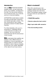
... new series includes a two monoblock amps, six 2-channel, and four 4-channel amplifiers. page 2 When first unpacking your system regardless of the nature of the items below. All PHANTOM models feature variable low pass and high pass crossovers and variable input gain controls. For further flexibility in the use of a subwoofer, 0-+18dB Bass Boost control has been included on all designed in many different kinds of installations...
... new series includes a two monoblock amps, six 2-channel, and four 4-channel amplifiers. page 2 When first unpacking your system regardless of the nature of the items below. All PHANTOM models feature variable low pass and high pass crossovers and variable input gain controls. For further flexibility in the use of a subwoofer, 0-+18dB Bass Boost control has been included on all designed in many different kinds of installations...
User Manual in English
Page 3
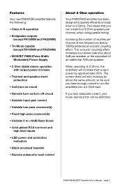
... Width Modulated) Power Supply • 2 Ohm stable stereo operation with output power increase • Thermal and speaker short protection • Soft turn-on circuit • Remote turn-on/turn-off circuit • Variable input gain control • Variable low pass crossover(s) • Fixed high pass crossover(s) • Variable 0 to +18dB Bass Boost • Gold-plated RCA low level and high level inputs • LED power and protection indicators • Black anodized heatsink • Remote subwoofer level control About 2 Ohm operation Your PHANTOM amplifier has been designed...
... Width Modulated) Power Supply • 2 Ohm stable stereo operation with output power increase • Thermal and speaker short protection • Soft turn-on circuit • Remote turn-on/turn-off circuit • Variable input gain control • Variable low pass crossover(s) • Fixed high pass crossover(s) • Variable 0 to +18dB Bass Boost • Gold-plated RCA low level and high level inputs • LED power and protection indicators • Black anodized heatsink • Remote subwoofer level control About 2 Ohm operation Your PHANTOM amplifier has been designed...
User Manual in English
Page 4
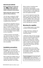
... the mounting surface is turned off while connecting the input jacks and speaker terminals. If this unit yourself. Confirm that supplied with a fuse identical to become damp or wet from water or drinks. There are dangerous voltages present within the unit. come familiar with a felt tip pen. 4. Mounting the amplifier 1. PHANTOM MOSFET Amplifier User's Manual - Refer any repairs to a qualified service technician. • To...
... the mounting surface is turned off while connecting the input jacks and speaker terminals. If this unit yourself. Confirm that supplied with a fuse identical to become damp or wet from water or drinks. There are dangerous voltages present within the unit. come familiar with a felt tip pen. 4. Mounting the amplifier 1. PHANTOM MOSFET Amplifier User's Manual - Refer any repairs to a qualified service technician. • To...
User Manual in English
Page 5
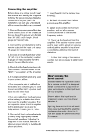
... audio distortion. Connect an empty fuse holder within 18" (45 cm) of the car. Connect all crossover controls/switches to the desired frequency points. 10. Then set all speakers, following the diagrams in your amplifier. Do not adjust this input level to maximum unless your particular installation. PHANTOM MOSFET Amplifier User's Manual - Be sure to observe proper polarity to obtain best results. Connect the power ground terminal to engage. Then run 8 gauge (or heavier) cable...
... audio distortion. Connect an empty fuse holder within 18" (45 cm) of the car. Connect all crossover controls/switches to the desired frequency points. 10. Then set all speakers, following the diagrams in your amplifier. Do not adjust this input level to maximum unless your particular installation. PHANTOM MOSFET Amplifier User's Manual - Be sure to observe proper polarity to obtain best results. Connect the power ground terminal to engage. Then run 8 gauge (or heavier) cable...
User Manual in English
Page 6
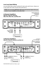
... high low BASS BOOST CH3/4 min 50Hz 45Hz INPUT SENSITIVITY INPUT LEVEL high pass low pass CH1/2 max 500Hz 90Hz full mode 0 +18dB CROSSOVER REMOTE SUBWOOFER LEVEL CONTROL min 100mV-2V 2V-8V 50Hz 45Hz high full low POWER PROTECTION FO UR C HANN EL MO SFET POWE R AMPLIFIER To FRONT Audio Outputs of head unit or signal processor To REAR Audio Outputs of head unit or signal processor PHANTOM MOSFET Amplifier User's Manual - Low Level Input Wiring Low-level (RCA) input wiring is preferred for best audio...
... high low BASS BOOST CH3/4 min 50Hz 45Hz INPUT SENSITIVITY INPUT LEVEL high pass low pass CH1/2 max 500Hz 90Hz full mode 0 +18dB CROSSOVER REMOTE SUBWOOFER LEVEL CONTROL min 100mV-2V 2V-8V 50Hz 45Hz high full low POWER PROTECTION FO UR C HANN EL MO SFET POWE R AMPLIFIER To FRONT Audio Outputs of head unit or signal processor To REAR Audio Outputs of head unit or signal processor PHANTOM MOSFET Amplifier User's Manual - Low Level Input Wiring Low-level (RCA) input wiring is preferred for best audio...
User Manual in English
Page 7
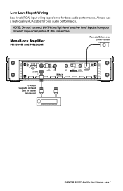
Low Level Input Wiring Low-level (RCA) input wiring is preferred for best audio performance. NOTE: Do not connect BOTH the high level and low level inputs from your receiver to your amplifier at the same time! page 7 MonoBlock Amplifier PH1500M and PH2500M Remote Subwoofer Level Control R POWER R L HIGH LEVEL INPUTS LOW INPUTS L 2V-8V 100mV-2V min max INPUT SENSITIVITY INPUT LEVEL 0 +18dB BASS BOOST LOW FULL MODE CROSSOVER 45Hz 90Hz LOW PASS FREQUENCY PROTECTION REMOTE SUBWOOFER LEVEL CONTROL M OSF E T M ONOBL OCK POWE R AM PL I FI E R To Audio Outputs of head unit or...
Low Level Input Wiring Low-level (RCA) input wiring is preferred for best audio performance. NOTE: Do not connect BOTH the high level and low level inputs from your receiver to your amplifier at the same time! page 7 MonoBlock Amplifier PH1500M and PH2500M Remote Subwoofer Level Control R POWER R L HIGH LEVEL INPUTS LOW INPUTS L 2V-8V 100mV-2V min max INPUT SENSITIVITY INPUT LEVEL 0 +18dB BASS BOOST LOW FULL MODE CROSSOVER 45Hz 90Hz LOW PASS FREQUENCY PROTECTION REMOTE SUBWOOFER LEVEL CONTROL M OSF E T M ONOBL OCK POWE R AM PL I FI E R To Audio Outputs of head unit or...
User Manual in English
Page 8
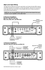
... head unit lacks RCA outputs. High Level Input Wiring The high level input(s) should only be used when your amplifier at the same time! 2-Channel Amplifiers PH2.500, PH2.600, PH2.800, PH2.1000, PH2.1300, and PH2.1500 Remote Subwoofer Level Control R POWER R L HIGH LEVEL INPUTS LOW INPUTS L 100mV-2V 2V-8V INPUT SENSITIVITY min max INPUT LEVEL 0 +18dB 50Hz 500Hz HIGH FULL LOW BASS BOOST HIGH PASS MODE FREQUENCY CROSSOVER 45Hz 90Hz LOW PASS FREQUENCY PROTECTION REMOTE SUBWOOFER LEVEL CONTROL TWO C HANNE L M OSF ET POWE R A MPL IFIER R+ R- L+ To Speaker Terminals...
... head unit lacks RCA outputs. High Level Input Wiring The high level input(s) should only be used when your amplifier at the same time! 2-Channel Amplifiers PH2.500, PH2.600, PH2.800, PH2.1000, PH2.1300, and PH2.1500 Remote Subwoofer Level Control R POWER R L HIGH LEVEL INPUTS LOW INPUTS L 100mV-2V 2V-8V INPUT SENSITIVITY min max INPUT LEVEL 0 +18dB 50Hz 500Hz HIGH FULL LOW BASS BOOST HIGH PASS MODE FREQUENCY CROSSOVER 45Hz 90Hz LOW PASS FREQUENCY PROTECTION REMOTE SUBWOOFER LEVEL CONTROL TWO C HANNE L M OSF ET POWE R A MPL IFIER R+ R- L+ To Speaker Terminals...

User Manual in English
Page 9
...PH2500M R POWER R L HIGH LEVEL INPUTS LOW INPUTS L 2V-8V 100mV-2V min max INPUT SENSITIVITY INPUT LEVEL 0 +18dB BASS BOOST LOW FULL MODE CROSSOVER 45Hz 90Hz LOW PASS FREQUENCY PROTECTION REMOTE SUBWOOFER LEVEL CONTROL M OSF E T M ONOBL OCK POWE R AM PL I FI E R R+ R- L+ To Speaker Terminals of the amplifier. High Level Input Wiring The high level input(s) should only be used when your amplifier at the same time! If the RCA outputs are not present, connect the speaker outputs from your receiver to the high level input connector of head unit Remote Subwoofer Level Control...
...PH2500M R POWER R L HIGH LEVEL INPUTS LOW INPUTS L 2V-8V 100mV-2V min max INPUT SENSITIVITY INPUT LEVEL 0 +18dB BASS BOOST LOW FULL MODE CROSSOVER 45Hz 90Hz LOW PASS FREQUENCY PROTECTION REMOTE SUBWOOFER LEVEL CONTROL M OSF E T M ONOBL OCK POWE R AM PL I FI E R R+ R- L+ To Speaker Terminals of the amplifier. High Level Input Wiring The high level input(s) should only be used when your amplifier at the same time! If the RCA outputs are not present, connect the speaker outputs from your receiver to the high level input connector of head unit Remote Subwoofer Level Control...
User Manual in English
Page 10
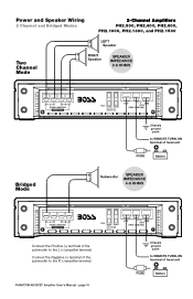
...- Power and Speaker Wiring 2 Channel and Bridged Modes 2-Channel Amplifiers PH2.500, PH2.600, PH2.800, PH2.1000, PH2.1300, and PH2.1500 Two Channel Mode + LEFT - page 10 +12V GND REMOTE POWER CONNECTIONS Chassis ground point to REMOTE TURN-ON terminal of head unit FUSE Battery Subwoofer SPEAKER IMPEDANCE 4-8 OHMS L R SPEAKER CONNECTIONS BRIDGED MODE FUSES Connect the Positive (+) terminal of the subwoofer to the L (+) amplifier terminal. Connect the Negative (-) terminal of the subwoofer to the R (-) amplifier terminal. Speaker + - PHANTOM MOSFET Amplifier User...
...- Power and Speaker Wiring 2 Channel and Bridged Modes 2-Channel Amplifiers PH2.500, PH2.600, PH2.800, PH2.1000, PH2.1300, and PH2.1500 Two Channel Mode + LEFT - page 10 +12V GND REMOTE POWER CONNECTIONS Chassis ground point to REMOTE TURN-ON terminal of head unit FUSE Battery Subwoofer SPEAKER IMPEDANCE 4-8 OHMS L R SPEAKER CONNECTIONS BRIDGED MODE FUSES Connect the Positive (+) terminal of the subwoofer to the L (+) amplifier terminal. Connect the Negative (-) terminal of the subwoofer to the R (-) amplifier terminal. Speaker + - PHANTOM MOSFET Amplifier User...
User Manual in English
Page 11
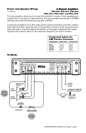
... of output channels. Be sure to REMOTE TURN-ON terminal of head unit FUSE Battery PHANTOM MOSFET Amplifier User's Manual - Tri-Mode Component values for the crossover frequency you to connect this amplifier to a pair of main speakers plus a subwoofer on one pair of this mode, put the crossover switches in MONO. Insert high pass filter capacitors and a low pass filter inductor into the wiring as shown below. The main speakers will operate in STEREO while the subwoofer...
... of output channels. Be sure to REMOTE TURN-ON terminal of head unit FUSE Battery PHANTOM MOSFET Amplifier User's Manual - Tri-Mode Component values for the crossover frequency you to connect this amplifier to a pair of main speakers plus a subwoofer on one pair of this mode, put the crossover switches in MONO. Insert high pass filter capacitors and a low pass filter inductor into the wiring as shown below. The main speakers will operate in STEREO while the subwoofer...
User Manual in English
Page 12
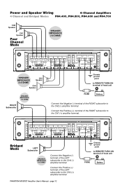
... to the CH2 (-) amplifier terminal. Power and Speaker Wiring 4-Channel Amplifiers 4 Channel and Bridged Modes PH4.400, PH4.500, PH4.600 and PH4.700 CH2 Speaker CH1 Speaker Four Channel Mode SPEAKER IMPEDANCE 2-8 OHMS CH1 CH2 SPEAKER CONNECTIONS BRIDGED MODE CH3 CH4 SPEAKER CONNECTIONS BRIDGED MODE +12V GND FUSES REMOTE POWER CONNECTIONS SPEAKER IMPEDANCE 2-8 OHMS CH3 Speaker CH4 Speaker SPEAKER IMPEDANCE 4-8 OHMS RIGHT Subwoofer Chassis ground point to REMOTE TURN-ON terminal of head unit FUSE Battery Connect the Negative (-) terminal of the LEFT subwoofer to the CH3...
... to the CH2 (-) amplifier terminal. Power and Speaker Wiring 4-Channel Amplifiers 4 Channel and Bridged Modes PH4.400, PH4.500, PH4.600 and PH4.700 CH2 Speaker CH1 Speaker Four Channel Mode SPEAKER IMPEDANCE 2-8 OHMS CH1 CH2 SPEAKER CONNECTIONS BRIDGED MODE CH3 CH4 SPEAKER CONNECTIONS BRIDGED MODE +12V GND FUSES REMOTE POWER CONNECTIONS SPEAKER IMPEDANCE 2-8 OHMS CH3 Speaker CH4 Speaker SPEAKER IMPEDANCE 4-8 OHMS RIGHT Subwoofer Chassis ground point to REMOTE TURN-ON terminal of head unit FUSE Battery Connect the Negative (-) terminal of the LEFT subwoofer to the CH3...
User Manual in English
Page 13
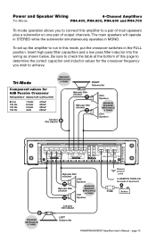
... CH2 SPEAKER CONNECTIONS BRIDGED MODE CH3 CH4 SPEAKER CONNECTIONS BRIDGED MODE +12V GND FUSES REMOTE POWER CONNECTIONS High pass filter crossover - page 13 Power and Speaker Wiring 4-Channel Amplifiers Tri-Mode PH4.400, PH4.500, PH4.600 and PH4.700 Tri-mode operation allows you wish to REMOTE TURN-ON terminal of head unit FUSE Battery PHANTOM MOSFET Amplifier User's Manual - To set up the amplifier to a pair of main speakers plus a subwoofer on one pair of output channels. Tri-Mode SPEAKER IMPEDANCE 8 OHMS Component values for the crossover frequency you...
... CH2 SPEAKER CONNECTIONS BRIDGED MODE CH3 CH4 SPEAKER CONNECTIONS BRIDGED MODE +12V GND FUSES REMOTE POWER CONNECTIONS High pass filter crossover - page 13 Power and Speaker Wiring 4-Channel Amplifiers Tri-Mode PH4.400, PH4.500, PH4.600 and PH4.700 Tri-mode operation allows you wish to REMOTE TURN-ON terminal of head unit FUSE Battery PHANTOM MOSFET Amplifier User's Manual - To set up the amplifier to a pair of main speakers plus a subwoofer on one pair of output channels. Tri-Mode SPEAKER IMPEDANCE 8 OHMS Component values for the crossover frequency you...
User Manual in English
Page 14
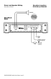
page 14 SPEAKER IMPEDANCE 2-8 OHMS SPEAKER CONNECTIONS FUSES +12V GND REMOTE POWER CONNECTIONS Chassis ground point to REMOTE TURN-ON terminal of head unit FUSE Battery PHANTOM MOSFET Amplifier User's Manual - Power and Speaker Wiring MonoBlock Mode MonoBlock Amplifiers PH1500M and PH2500M MonoBlock Mode + Speaker -
page 14 SPEAKER IMPEDANCE 2-8 OHMS SPEAKER CONNECTIONS FUSES +12V GND REMOTE POWER CONNECTIONS Chassis ground point to REMOTE TURN-ON terminal of head unit FUSE Battery PHANTOM MOSFET Amplifier User's Manual - Power and Speaker Wiring MonoBlock Mode MonoBlock Amplifiers PH1500M and PH2500M MonoBlock Mode + Speaker -
User Manual in English
Page 15
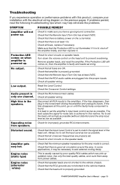
... the Input Level Control is set the head unit as high as possible (without distortion) and the amp input level as low as possible. Turn down the volume control on , then the amplifier is good air circulation around the amp. No output. Check that there is faulty and needs servicing. If the Protection LED still comes on the head unit to the amplifiers. Reset the Level Control. High hiss in Check the RCA interconnect cables. Distorted sound. Check all speaker wiring...
... the Input Level Control is set the head unit as high as possible (without distortion) and the amp input level as low as possible. Turn down the volume control on , then the amplifier is good air circulation around the amp. No output. Check that there is faulty and needs servicing. If the Protection LED still comes on the head unit to the amplifiers. Reset the Level Control. High hiss in Check the RCA interconnect cables. Distorted sound. Check all speaker wiring...


