
Parts Manual - English
Page 3
... parts List 75 Gat. Machine body 1 B. Needle bar rocking mechanism 5 F. Feed device mechanism 63 AE. Lower shaft mechanism 1 O. Lubrication 15 K. Accessories 71 Z2. Printed circuit board mechanism 51 X. CONTENTS A. Threading mechanism 19 Ll. Cloth control system mechanism 43 V2. Marker mechanism 51 Y. Rotary hook mechanism 13 J. Thread breakage detector (Option parts) 27 R. column, refer to changes in design without prior notice. 3 Parts supplied as complete assemblies are...
... parts List 75 Gat. Machine body 1 B. Needle bar rocking mechanism 5 F. Feed device mechanism 63 AE. Lower shaft mechanism 1 O. Lubrication 15 K. Accessories 71 Z2. Printed circuit board mechanism 51 X. CONTENTS A. Threading mechanism 19 Ll. Cloth control system mechanism 43 V2. Marker mechanism 51 Y. Rotary hook mechanism 13 J. Thread breakage detector (Option parts) 27 R. column, refer to changes in design without prior notice. 3 Parts supplied as complete assemblies are...
Parts Manual - English
Page 9
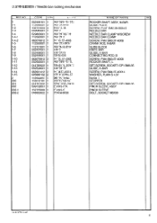
... t*:.*M-7'9Q, Cifk)-7* Tti(146X30 NAME OF PARTS RM ROCKER SHAFT ASSY, N-BAR GUIDE PLATE SCREW, FLAT SM2.38-56X4.5 NEEDLE BAR NEEDLE BAR CLAMP W/SCREW NEEDLE BAR CLAMP SCREW, PAN SM3.57-40X8 CRANK ROD, N-BAR SLIDE BLOCK KNIFE BAR GUIDE, K-BAR CONNECTING ROD, B SCREW, PAN SM3.57-40X8 ROCKER SHAFT, L SET SCREW, SOCKET (CP) SM6.35 GUIDE, K-BAR SCREW, PAN SM4.37-40X14 WASHER, PLAIN S 4.37 BUSH, L STOPPER SET SCREW, SOCKET (CP) SM6.35 PINCH SLEEVE...
... t*:.*M-7'9Q, Cifk)-7* Tti(146X30 NAME OF PARTS RM ROCKER SHAFT ASSY, N-BAR GUIDE PLATE SCREW, FLAT SM2.38-56X4.5 NEEDLE BAR NEEDLE BAR CLAMP W/SCREW NEEDLE BAR CLAMP SCREW, PAN SM3.57-40X8 CRANK ROD, N-BAR SLIDE BLOCK KNIFE BAR GUIDE, K-BAR CONNECTING ROD, B SCREW, PAN SM3.57-40X8 ROCKER SHAFT, L SET SCREW, SOCKET (CP) SM6.35 GUIDE, K-BAR SCREW, PAN SM4.37-40X14 WASHER, PLAIN S 4.37 BUSH, L STOPPER SET SCREW, SOCKET (CP) SM6.35 PINCH SLEEVE...
Parts Manual - English
Page 67
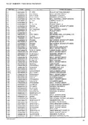
AD.AU Zrn / Feed device mechanism REF.NO CODE QTY b > x -( NAME OF PARTS RM 1-1 1-2 1-3 1-4 1-5 1-6 1-7 1-8 1-9 1-10 1-11 1-12 1-13 1-14 1-15 1-16 1-17 1-18 1-19 1-...TIMING PULLEY, B RING, THRUST SET SCREW, SOCKET (FT) M6X6 SPUR GEAR, 66 ;PA SET SCREW, SOCKET (FT) M5X5 KEY, 5X30 MOTOR SETTING PLATE BOLT, SOCKET M5X12 LINEAR GUIDE, 15X700 BOLT, SOCKET M4X14 WASHER, SPRING 2-4 FEED BRACKET BOLT, SOCKET M4X16 WASHER, SPRING 2-4 BELT HOLDER BOLT, SOCKET M5X16 LIMIT PLATE BOLT, SOCKET M5X12 RUBBER CAP, 10.5 CYLINDER ASSY AIR CYLINDER, 25X12 SPEED CONTROLLER BOLT, SOCKET M6X14 CYLINDER SUPPORT...
AD.AU Zrn / Feed device mechanism REF.NO CODE QTY b > x -( NAME OF PARTS RM 1-1 1-2 1-3 1-4 1-5 1-6 1-7 1-8 1-9 1-10 1-11 1-12 1-13 1-14 1-15 1-16 1-17 1-18 1-19 1-...TIMING PULLEY, B RING, THRUST SET SCREW, SOCKET (FT) M6X6 SPUR GEAR, 66 ;PA SET SCREW, SOCKET (FT) M5X5 KEY, 5X30 MOTOR SETTING PLATE BOLT, SOCKET M5X12 LINEAR GUIDE, 15X700 BOLT, SOCKET M4X14 WASHER, SPRING 2-4 FEED BRACKET BOLT, SOCKET M4X16 WASHER, SPRING 2-4 BELT HOLDER BOLT, SOCKET M5X16 LIMIT PLATE BOLT, SOCKET M5X12 RUBBER CAP, 10.5 CYLINDER ASSY AIR CYLINDER, 25X12 SPEED CONTROLLER BOLT, SOCKET M6X14 CYLINDER SUPPORT...
Instruction Manual - English
Page 3
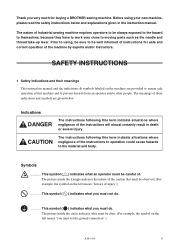
... symbol on the left means "beware of injury".) This symbol ( ) indicates what you must set the ground connection".) BAS-6150 1 Thank you very much for safe and correct operation of the instructions to operation could cause hazards to moving parts such as the needle and thread take-up lever. This symbol ( ) indicates what you must be well informed of instructions for buying a BROTHER sewing machine.
... symbol on the left means "beware of injury".) This symbol ( ) indicates what you must set the ground connection".) BAS-6150 1 Thank you very much for safe and correct operation of the instructions to operation could cause hazards to moving parts such as the needle and thread take-up lever. This symbol ( ) indicates what you must be well informed of instructions for buying a BROTHER sewing machine.
Instruction Manual - English
Page 4
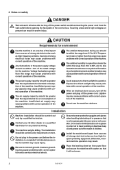
... the machine. Install the machine well apart from 45% to wear protective goggles and gloves when handling lubricating oil or grease so that it will not move. 2 BAS-6150 Otherwise, incorrect machine operation may cause problems with correct operation and a serious electrical shock. Touching areas where high voltages are presant can result in the power cord before opening the face plate of the machine. CAUTION...
... the machine. Install the machine well apart from 45% to wear protective goggles and gloves when handling lubricating oil or grease so that it will not move. 2 BAS-6150 Otherwise, incorrect machine operation may cause problems with correct operation and a serious electrical shock. Touching areas where high voltages are presant can result in the power cord before opening the face plate of the machine. CAUTION...
Instruction Manual - English
Page 5
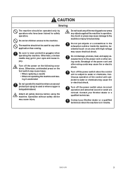
... replacing a needle • When not operating the machine and leav- Accidental touch on the foot switch may cause electrical shock. Do not touch any of the moving parts nor press any other wiring cords. Contact your Brother dealer or a qualified technician. Do not let children access to the power cord or other application than sewing. ing it unattended Do not operate the machine...
... replacing a needle • When not operating the machine and leav- Accidental touch on the foot switch may cause electrical shock. Do not touch any of the moving parts nor press any other wiring cords. Contact your Brother dealer or a qualified technician. Do not let children access to the power cord or other application than sewing. ing it unattended Do not operate the machine...
Instruction Manual - English
Page 6
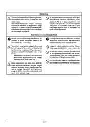
... the air supply and wait for electrical maintenance and inspection. 4 BAS-6150 Otherwise, unintended press on the foot switch may cause injury. Loss and others due to be done with the power switch and air supply on the foot switch may cause injury. • maintenance, adjustment, and repairment • replacement of any parts which use the pneumatic equipment. Ask your skin. Keep...
... the air supply and wait for electrical maintenance and inspection. 4 BAS-6150 Otherwise, unintended press on the foot switch may cause injury. Loss and others due to be done with the power switch and air supply on the foot switch may cause injury. • maintenance, adjustment, and repairment • replacement of any parts which use the pneumatic equipment. Ask your skin. Keep...
Instruction Manual - English
Page 7
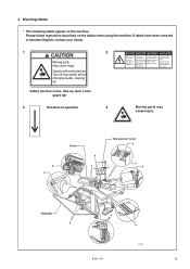
... off main switch and wait 5 minutes before changing needle, cleaning etc. Safety devices: cover, take-up lever cover 2 1434S 3 Guard bar 4 4 4 BAS-6150 1432S 5 Eteindrel'interrupteur et attendre 5 minutes avantd' ouvrir le capot Un voltaje inadecuado puede provocar las heridas. Operate with safety devices. 3 Warning labels * The following labels appear on the labels when using the machine. Please follow instruction described on the...
... off main switch and wait 5 minutes before changing needle, cleaning etc. Safety devices: cover, take-up lever cover 2 1434S 3 Guard bar 4 4 4 BAS-6150 1432S 5 Eteindrel'interrupteur et attendre 5 minutes avantd' ouvrir le capot Un voltaje inadecuado puede provocar las heridas. Operate with safety devices. 3 Warning labels * The following labels appear on the labels when using the machine. Please follow instruction described on the...

Instruction Manual - English
Page 8
... main plate 18 4. Initialization at the time of the 3-pedal foot switch 13 3-4. Machine stop reset 38 3-3. How to thread the lower thread 22 4-5. Installation of power ON 26 Chapter 2 Sewing flow 27 1. Air pressure setting 17 3-8. How to stop switch cover 14 3-6. Description of the stacker (option 14 3-7. Attachment of the panel 28 1-2. Machine stop 38 3-1. How to wind the lower thread 21 4-4. Name of upper and lower threads 24 4-8. Retention of parts...
... main plate 18 4. Initialization at the time of the 3-pedal foot switch 13 3-4. Machine stop reset 38 3-3. How to thread the lower thread 22 4-5. Installation of power ON 26 Chapter 2 Sewing flow 27 1. Air pressure setting 17 3-8. How to stop switch cover 14 3-6. Description of the stacker (option 14 3-7. Attachment of the panel 28 1-2. Machine stop 38 3-1. How to wind the lower thread 21 4-4. Name of upper and lower threads 24 4-8. Retention of parts...
Instruction Manual - English
Page 9
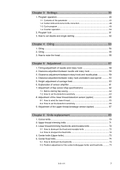
... specifications 62 7-1. Adjustment of the center knife(upper knife) and fixed knife .......... 74 BAS-6150 7 Clearance adjustment between rotary hook and bobbin case opener 60 5. Height adjustment of the upper thread breakage sensor (option 67 Chapter 6 Knife replacement 69 1. How to set the detection sensitivity 66 9. Adjustment of carriage feed 60 6. How to dismount the fixed and movable knife 72 3-2. Timing adjustment of the parameter 40 1-2. Before starting flap sewing 62 7-2. Clearance adjustment between needle...
... specifications 62 7-1. Adjustment of the center knife(upper knife) and fixed knife .......... 74 BAS-6150 7 Clearance adjustment between rotary hook and bobbin case opener 60 5. Height adjustment of the upper thread breakage sensor (option 67 Chapter 6 Knife replacement 69 1. How to set the detection sensitivity 66 9. Adjustment of carriage feed 60 6. How to dismount the fixed and movable knife 72 3-2. Timing adjustment of the parameter 40 1-2. Before starting flap sewing 62 7-2. Clearance adjustment between needle...
Instruction Manual - English
Page 12
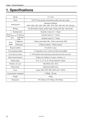
Chapter 1 Machine Preparation 1. back tack Seam length Minimum Maximum Program number Cycle program number Lower thread counter Sensor check function Needle gauge Needle to be used Rotary hook Power Air pressure/air consumption Weight Dimensions 151-6150 118-U73 (the machine with double needles and center knife) Maximum 3000rpm (3000, 2800, 2500, 2200, 2000, 1800, 1500, 1200, 1000, 800, 500, 200 rpm) Parallel double welting, parallel single welting (with...
Chapter 1 Machine Preparation 1. back tack Seam length Minimum Maximum Program number Cycle program number Lower thread counter Sensor check function Needle gauge Needle to be used Rotary hook Power Air pressure/air consumption Weight Dimensions 151-6150 118-U73 (the machine with double needles and center knife) Maximum 3000rpm (3000, 2800, 2500, 2200, 2000, 1800, 1500, 1200, 1000, 800, 500, 200 rpm) Parallel double welting, parallel single welting (with...
Instruction Manual - English
Page 19
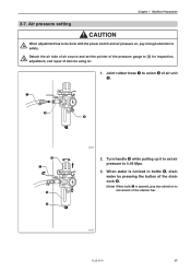
... be done with the power switch and air pressure on, pay due attention to [0] for inspection, adjustment, and repair of devices using air. 1. Joint rubber hose q to union e of the stacker bar. 1447S BAS-6150 17 q e w r u t y 1446S 2. Turn handle r while pulling up it to set the pointer of the pressure gauge to movement of air unit w. Chapter 1 Machine Preparation 3-7. When water...
... be done with the power switch and air pressure on, pay due attention to [0] for inspection, adjustment, and repair of devices using air. 1. Joint rubber hose q to union e of the stacker bar. 1447S BAS-6150 17 q e w r u t y 1446S 2. Turn handle r while pulling up it to set the pointer of the pressure gauge to movement of air unit w. Chapter 1 Machine Preparation 3-7. When water...

Instruction Manual - English
Page 25
... thread into a needle hole inside to thread the upper thread CAUTION Turn off the power switch for easy threading and good prevention of the thread come-off at the occurrence of thread by pressing the reset switch. 1. Adjusting the thread tension Stronger Weaker 1630S Stronger Weaker Weaker Stronger 1631S After the lower thread tension has been adjusted, adjust the upper thread tension. BAS-6150 23 Chapter 1 Machine Preparation 4-5. Proceed to set the thread take-up q at the highest position...
... thread into a needle hole inside to thread the upper thread CAUTION Turn off the power switch for easy threading and good prevention of the thread come-off at the occurrence of thread by pressing the reset switch. 1. Adjusting the thread tension Stronger Weaker 1630S Stronger Weaker Weaker Stronger 1631S After the lower thread tension has been adjusted, adjust the upper thread tension. BAS-6150 23 Chapter 1 Machine Preparation 4-5. Proceed to set the thread take-up q at the highest position...
Instruction Manual - English
Page 30
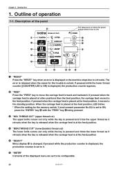
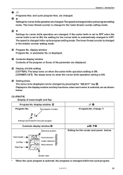
... machine stops due to a trouble. If pressed while the production counter is displayed, the production counter is set to be configurable. 28 BAS-6150 Outline of the panel !2 The lamp turns on when the power supply switch is set to ON, press the "ENTER" key y with the "FEED" key w being pressed. Description of operation 1-1. r "BBN.THREAD CUT" (lower(bobbin) thread cut ) The upper knife comes...
... machine stops due to a trouble. If pressed while the production counter is displayed, the production counter is set to be configurable. 28 BAS-6150 Outline of the panel !2 The lamp turns on when the power supply switch is set to ON, press the "ENTER" key y with the "FEED" key w being pressed. Description of operation 1-1. r "BBN.THREAD CUT" (lower(bobbin) thread cut ) The upper knife comes...
Instruction Manual - English
Page 31
... setting mode. The speed is changed in the cycle program setting mode. oM Settings for the cycle program. The lower thread counter is changed in the lower thread counter setting mode. change *1 Setting is changed in the bobbin counter setting mode. !0 Program No. Contents display window !1 Reference position Seam length Left flap Right flap Front reference Center reference Rear reference Li, Mo Setting for the center and corner knives Stacker used...
... setting mode. The speed is changed in the cycle program setting mode. oM Settings for the cycle program. The lower thread counter is changed in the lower thread counter setting mode. change *1 Setting is changed in the bobbin counter setting mode. !0 Program No. Contents display window !1 Reference position Seam length Left flap Right flap Front reference Center reference Rear reference Li, Mo Setting for the center and corner knives Stacker used...
Instruction Manual - English
Page 43
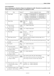
... to +. start of sewing and end of sewing 3 Flap correction - end of sewing 4 Flap clamp 5 Flap clamp operation 6 Sewing speed at lock stitch sewing. NO. Chapter 3 Settings List of parameters Items in [Display] are character strings to be displayed on LED. Characters in quotation marks shows those in the character strings to be performed for the flap clamp. (0 to 3) Refer to 5 needles BAS-6150 1.0 1 41 start of sewing in common...
... to +. start of sewing and end of sewing 3 Flap correction - end of sewing 4 Flap clamp 5 Flap clamp operation 6 Sewing speed at lock stitch sewing. NO. Chapter 3 Settings List of parameters Items in [Display] are character strings to be displayed on LED. Characters in quotation marks shows those in the character strings to be performed for the flap clamp. (0 to 3) Refer to 5 needles BAS-6150 1.0 1 41 start of sewing in common...
Instruction Manual - English
Page 79
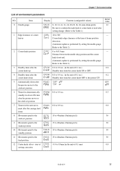
... after the carriage feed down 8 Movement speed to the cloth set position 9 Movement speed to the stacker position 10 Movement speed to the standby position 11 Movement speed to 9.9mm (in the unit of corner knife is used after setting change. (Refer to the Table 1.) 10 to 465.0 mm Distance between the needle drop position and the corner knife front end. (Automatic update is performed by setting the needle gauge.
... after the carriage feed down 8 Movement speed to the cloth set position 9 Movement speed to the stacker position 10 Movement speed to the standby position 11 Movement speed to 9.9mm (in the unit of corner knife is used after setting change. (Refer to the Table 1.) 10 to 465.0 mm Distance between the needle drop position and the corner knife front end. (Automatic update is performed by setting the needle gauge.
Instruction Manual - English
Page 100
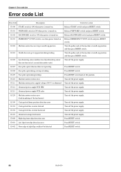
... feed motor Right flap front edge detection error Left flap front edge detection error Front edge of right flap could not be detected Corrective action Release START switch and press RESET switch. Press RESET switch. 98 BAS-6150 E-102 BACKWARD switch is ON when power is turned on in 1 second after motor starts) Face plate open when machine not operating Face plate open during sewing or feeding Face plate open during feeding Machine motor rotation error Machine motor power...
... feed motor Right flap front edge detection error Left flap front edge detection error Front edge of right flap could not be detected Corrective action Release START switch and press RESET switch. Press RESET switch. 98 BAS-6150 E-102 BACKWARD switch is ON when power is turned on in 1 second after motor starts) Face plate open when machine not operating Face plate open during sewing or feeding Face plate open during feeding Machine motor rotation error Machine motor power...
Instruction Manual - English
Page 102
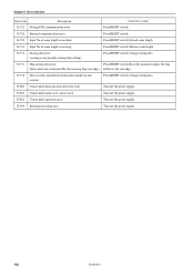
... seam length is not possible sewing data setting) Press RESET switch. E-733 Flap sewing data error Press RESET switch. Reset the position to make an end overrun Press RESET switch. Chapter 9 Error code List Error Code Description Corrective action E-725 Sewing PCB communication error Press RESET switch. E-726 External communication error Press RESET switch. E-801 Corner knife motor over current error Turn off the power supply. 100 BAS-6150 E-999 Internal processing error Turn off the power supply. E-732 Sewing data error (sewing...
... seam length is not possible sewing data setting) Press RESET switch. E-733 Flap sewing data error Press RESET switch. Reset the position to make an end overrun Press RESET switch. Chapter 9 Error code List Error Code Description Corrective action E-725 Sewing PCB communication error Press RESET switch. E-726 External communication error Press RESET switch. E-801 Corner knife motor over current error Turn off the power supply. 100 BAS-6150 E-999 Internal processing error Turn off the power supply. E-732 Sewing data error (sewing...
Instruction Manual - English
Page 104
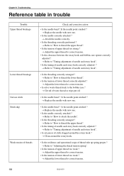
... needle and rotary hook". • Is the timing of needle and rotary hook correctly adjusted ? → Refer to "Timing adjustment of needle and rotary hook". • Is the threading correctly arranged ? → Refer to "How to thread the lower thread". • Is the tension of lower thread correctly adjusted ? → Adjust the lower thread to correct tension. • Is oil or waste thread stuck to correct tension. 102 BAS-6150 Chapter 10 Troubleshooting Reference table in trouble Trouble Upper thread breakage Lower thread breakage Uneven stitch Stitch...
... needle and rotary hook". • Is the timing of needle and rotary hook correctly adjusted ? → Refer to "Timing adjustment of needle and rotary hook". • Is the threading correctly arranged ? → Refer to "How to thread the lower thread". • Is the tension of lower thread correctly adjusted ? → Adjust the lower thread to correct tension. • Is oil or waste thread stuck to correct tension. 102 BAS-6150 Chapter 10 Troubleshooting Reference table in trouble Trouble Upper thread breakage Lower thread breakage Uneven stitch Stitch...


