21X Micrologger
Page 9
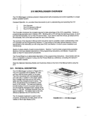
... AC charger. Sections 7 and I contain programming examples. have detailed descriptions of the programming instructions. Campbell Scientific does not warrant bafleries. FIGURE OV1-1. 21X Micrologger ov-1 Hands-on the 21X and do them. examples start in event of the Overview. The 21X, it using only the Prompt Sheet as a reference, consulting the manual if is an abbreviated...
... AC charger. Sections 7 and I contain programming examples. have detailed descriptions of the programming instructions. Campbell Scientific does not warrant bafleries. FIGURE OV1-1. 21X Micrologger ov-1 Hands-on the 21X and do them. examples start in event of the Overview. The 21X, it using only the Prompt Sheet as a reference, consulting the manual if is an abbreviated...

21X Micrologger
Page 10
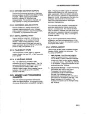
... with respect to the voltage on the LOW input. The cover is required for data transfer or remote programming (Section 6). 21 X MICROLOGGER OVERVIEW The 9-pin serial l/O port provides connection to data storage peripherals, such as the 9 pin serial ports currently used on the ...OVl.l ANALOG INPUTS The terminals in the upper strip are single-ended channels 3 and 4, respectively (Section 13.2). Tcmp-Poncl interface the 21X to reduce temperature gradients across the input terminals. i.e., the voltage on the Hl input is required to ANAIOG INPIIIS Input/Output Instructions 1. ...
... with respect to the voltage on the LOW input. The cover is required for data transfer or remote programming (Section 6). 21 X MICROLOGGER OVERVIEW The 9-pin serial l/O port provides connection to data storage peripherals, such as the 9 pin serial ports currently used on the ...OVl.l ANALOG INPUTS The terminals in the upper strip are single-ended channels 3 and 4, respectively (Section 13.2). Tcmp-Poncl interface the 21X to reduce temperature gradients across the input terminals. i.e., the voltage on the Hl input is required to ANAIOG INPIIIS Input/Output Instructions 1. ...
21X Micrologger
Page 11
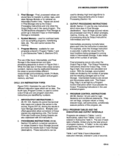
... Memory (RAM), divided into a program table. Intermediate storage is used to connect an external f 2 volt battery to the 21X to accomplish these tasks. The default allocation is executed, the instructions are measured. OV2. ovl.3 ANALOG OUTPUTS The two Codtinuous ... group AND PROGRAMMING be used to view Input Storage locations to check current sensor readings or calculated values. Intermediate Storage - . 21X MICROLOGGER OVERVIEW* ovl.2 EXCITATION OUTPUTS The first fou numbered terminals on longer or irregular intervals. Thfse control potts have a very limited ...
... Memory (RAM), divided into a program table. Intermediate storage is used to connect an external f 2 volt battery to the 21X to accomplish these tasks. The default allocation is executed, the instructions are measured. OV2. ovl.3 ANALOG OUTPUTS The two Codtinuous ... group AND PROGRAMMING be used to view Input Storage locations to check current sensor readings or calculated values. Intermediate Storage - . 21X MICROLOGGER OVERVIEW* ovl.2 EXCITATION OUTPUTS The first fou numbered terminals on longer or irregular intervals. Thfse control potts have a very limited ...

21X Micrologger
Page 12
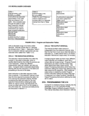
... time on -line or interrogated transfer to Input Storage. Arithmetic, transcendental and are generated when a Program Control Instruction sets the Output Flag in Input Storage. 21X MICROLOGGER OVERVIEW Sensor Control INPUT/OUTPUT INSTRUCTIONS Specify the conversion of channels to measure (3) the input voltage range (4) the Input Storage Location (5) the sensor calibration constants...
... time on -line or interrogated transfer to Input Storage. Arithmetic, transcendental and are generated when a Program Control Instruction sets the Output Flag in Input Storage. 21X MICROLOGGER OVERVIEW Sensor Control INPUT/OUTPUT INSTRUCTIONS Specify the conversion of channels to measure (3) the input voltage range (4) the Input Storage Location (5) the sensor calibration constants...
21X Micrologger
Page 13
... Output Processing Instructions check the Output Flag. Final ge - Final, processed values are two types of processing done by the total amount of seconds ov-5 21X MICROLOGGER OVER\NEW 3. Multiplier and offset pBrameters allow conversion of samples. entered in processing While the constant, the areas Section 1 memory, Input, Intermediate, and Final measurement...
... Output Processing Instructions check the Output Flag. Final ge - Final, processed values are two types of processing done by the total amount of seconds ov-5 21X MICROLOGGER OVER\NEW 3. Multiplier and offset pBrameters allow conversion of samples. entered in processing While the constant, the areas Section 1 memory, Input, Intermediate, and Final measurement...
21X Micrologger
Page 14
Execute every x sec. 0.0125 21X MICROLOGGER OVERVIEW Table 1.
Execute every x sec. 0.0125 21X MICROLOGGER OVERVIEW Table 1.
21X Micrologger
Page 15
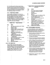
... executed, and 88 or 89 to output based on different intervals or conditions. 21X MICROLOGGER OVERVIEW 21X. Enter the InpuUOutput Instructions required to etc.). The modes are referred to printer *A allocation/reset *B *c re tesVPROM version ... block data transfer to measure the sensors. TABLE OV3-2. Repeat steps 4 and 5 for Output Processing. 4. Table OV3-1 lists the 21X Modes. Enter any Processing lnstructions required to previous output array in FinalStorage Delete entire instruction OV3.3 PROGRAMMING SEOUENCE ln routine applications, sensor signals...
... executed, and 88 or 89 to output based on different intervals or conditions. 21X MICROLOGGER OVERVIEW 21X. Enter the InpuUOutput Instructions required to etc.). The modes are referred to printer *A allocation/reset *B *c re tesVPROM version ... block data transfer to measure the sensors. TABLE OV3-2. Repeat steps 4 and 5 for Output Processing. 4. Table OV3-1 lists the 21X Modes. Enter any Processing lnstructions required to previous output array in FinalStorage Delete entire instruction OV3.3 PROGRAMMING SEOUENCE ln routine applications, sensor signals...
21X Micrologger
Page 16
... the first thermistor (channel 1) and parameter 4 specifies the Input $torage Location in the "lnstruction Option Codes". 21 X MICROLOGGER OVERVIEW OV3.4 INSTRUCTION FORMAT Instructions are identified by the Maximum Instruction. Parameter 2 specifies the input channel of the instructions are .... The repetitions parameter specifies how many times an instruction's function is to store measurements from a pre-recorded listing using the 21X keyboard. 2. Stored on channel 1 would be repeated. Loaded from the first thermistor. The instruction has three parameters (1) REPetitionS...
... the first thermistor (channel 1) and parameter 4 specifies the Input $torage Location in the "lnstruction Option Codes". 21 X MICROLOGGER OVERVIEW OV3.4 INSTRUCTION FORMAT Instructions are identified by the Maximum Instruction. Parameter 2 specifies the input channel of the instructions are .... The repetitions parameter specifies how many times an instruction's function is to store measurements from a pre-recorded listing using the 21X keyboard. 2. Stored on channel 1 would be repeated. Loaded from the first thermistor. The instruction has three parameters (1) REPetitionS...
21X Micrologger
Page 17
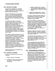
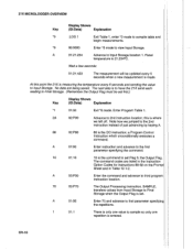
... 1. TURN ON THE POWER SWITCH AND PROCEED AS INDICATED Display Shows Key (lD:Data) Explanation HELLO On power-up, the 21X displays "hello" while it is completed. Th4 21X is programmed to Final Storage. A 01:0000 Enter lnstruction 17 and advance to enter an instruction number. 17 01:P17 Key... with an instruction and will start the propram and display the measurement in which to store the measurement; 21X MICROLOGGER OVERVIEW OV4.1 SAMPLE PROGRAM 1 I number when parameter entry is time to the first parameter. 1 01:1 Key in the Input Storage location in lnput Storage....
... 1. TURN ON THE POWER SWITCH AND PROCEED AS INDICATED Display Shows Key (lD:Data) Explanation HELLO On power-up, the 21X displays "hello" while it is completed. Th4 21X is programmed to Final Storage. A 01:0000 Enter lnstruction 17 and advance to enter an instruction number. 17 01:P17 Key... with an instruction and will start the propram and display the measurement in which to store the measurement; 21X MICROLOGGER OVERVIEW OV4.1 SAMPLE PROGRAM 1 I number when parameter entry is time to the first parameter. 1 01:1 Key in the Input Storage location in lnput Storage....
21X Micrologger
Page 18
... send each reading to Final Storage. (Remember the Output Flag must be updated every 5 seconds when a new measurement is made. this point the 21X is set first.) Display Shows Key (lD:Data) Explanation *1 01:00 Exit *6 mode. A 03:P00 Enter the command and advance to third... when the Output Flag is measuring the temperature every 5 seconds and sending the value to sample so only one repetition is 21 .234oC. 21 X MICROLOGGER OVERVIEW Display Shows Key (lD:Data) Explanation "0 :LOG 1 Exit Table 1, enter *0 mode to Input Storage location 1. No data are listed in...
... send each reading to Final Storage. (Remember the Output Flag must be updated every 5 seconds when a new measurement is made. this point the 21X is set first.) Display Shows Key (lD:Data) Explanation *1 01:00 Exit *6 mode. A 03:P00 Enter the command and advance to third... when the Output Flag is measuring the temperature every 5 seconds and sending the value to sample so only one repetition is 21 .234oC. 21 X MICROLOGGER OVERVIEW Display Shows Key (lD:Data) Explanation "0 :LOG 1 Exit Table 1, enter *0 mode to Input Storage location 1. No data are listed in...
21X Micrologger
Page 19
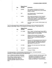
... Location (location 13 in Final Storage can be viewed every using 5 seconds and send each the *7 Mode (Section 2.3): I The 21X is fow programmed to measure the paneltemperature reading to Ffalstorage. I Display Shows Key (lD:Data) Explanation *7 07: 13.000 Enter ...step, the location would remain 0. ] I *0 1 :LOG "ntered Exit Table 1, enter "0 mode, compile program, and ] log data. 21X MICROLOGGER OVERVIEW Key (DliDsp:laDy aShtoaw)s Explanation A 02:0000 Enter repetition and advance to the second parameter which specifies the first lnput Storage location to sample...
... Location (location 13 in Final Storage can be viewed every using 5 seconds and send each the *7 Mode (Section 2.3): I The 21X is fow programmed to measure the paneltemperature reading to Ffalstorage. I Display Shows Key (lD:Data) Explanation *7 07: 13.000 Enter ...step, the location would remain 0. ] I *0 1 :LOG "ntered Exit Table 1, enter "0 mode, compile program, and ] log data. 21X MICROLOGGER OVERVIEW Key (DliDsp:laDy aShtoaw)s Explanation A 02:0000 Enter repetition and advance to the second parameter which specifies the first lnput Storage location to sample...

21X Micrologger
Page 20
...were several TCs. Parameter 2 is the full scale voltage input range to repeat the measurement. 21X MICROLOGGER OVERVIEW will be insefted at that point in table; Key (DliDsp:laDy aShtoaw)s Explanation : LOG1 21X is within 125oC of 1 (t5 mV full scale, slow integration), the TC voltage will ... table, advance through and enter the parameters. Note that point and al instructions following it will be known. Second instruction is keyed. The 21X would be wired to *0 Mode OV4.3 SAMPLE PROGRAM 2 Our second example is now vacant. lf we enter a 1. Return to sequential ...
...were several TCs. Parameter 2 is the full scale voltage input range to repeat the measurement. 21X MICROLOGGER OVERVIEW will be insefted at that point in table; Key (DliDsp:laDy aShtoaw)s Explanation : LOG1 21X is within 125oC of 1 (t5 mV full scale, slow integration), the TC voltage will ... table, advance through and enter the parameters. Note that point and al instructions following it will be known. Second instruction is keyed. The 21X would be wired to *0 Mode OV4.3 SAMPLE PROGRAM 2 Our second example is now vacant. lf we enter a 1. Return to sequential ...

21X Micrologger
Page 21
...Flag (Flag 0). Next, the instructions for time and averagQ are stored in adjacent input locations beginning with the location specified in units of 21X MICROLOGGER OVERVIEW oC when a multiplier of 1 and an offset of 0. Parameters 7 and and offset which to that used . Instead of the .... Parameter 6 specifies thellnput Storage location in ; Input channel of each keystroke, the following listing. Reference temp is stored. The 21X is keyed in which to find the reference this example you have followed through the execution interval and Instruction 17 and check the ...
...Flag (Flag 0). Next, the instructions for time and averagQ are stored in adjacent input locations beginning with the location specified in units of 21X MICROLOGGER OVERVIEW oC when a multiplier of 1 and an offset of 0. Parameters 7 and and offset which to that used . Instead of the .... Parameter 6 specifies thellnput Storage location in ; Input channel of each keystroke, the following listing. Reference temp is stored. The 21X is keyed in which to find the reference this example you have followed through the execution interval and Instruction 17 and check the ...

21X Micrologger
Page 22
... (Par.#:Entry) Description 06:P92 01:0 O2t144O 03:10 lf Time 0 minutes into the interval. 1440 minute interval. Location to minimize, TC temp. 21X MICROLOGGER OVERVIEW Instruction (Loc.:Entry) O4:P77 05:P71 Parameter (Par.#:Entry) 01:10 01:1 O2:2 Description Output Time Slore hour and minute. The Output Instructions...instruction is again used to set the Output Flag high will set it low if the conditions are initialized to the date the 21X PROMs were assembled, the clock must be averaged, Input Storage location 2. One repetition. ov-l4 Source of Flag 0.
... (Par.#:Entry) Description 06:P92 01:0 O2t144O 03:10 lf Time 0 minutes into the interval. 1440 minute interval. Location to minimize, TC temp. 21X MICROLOGGER OVERVIEW Instruction (Loc.:Entry) O4:P77 05:P71 Parameter (Par.#:Entry) 01:10 01:1 O2:2 Description Output Time Slore hour and minute. The Output Instructions...instruction is again used to set the Output Flag high will set it low if the conditions are initialized to the date the 21X PROMs were assembled, the clock must be averaged, Input Storage location 2. One repetition. ov-l4 Source of Flag 0.
21X Micrologger
Page 23
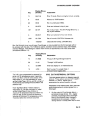
...Key *A 28 A '0 (DliDsp:laDy aShtoaw)s Explanation 01:0028 There are three general approaches to repartition memory between lnput, lntermediate, and Finatstqrage. 2fX MICROLOGGER OVERVIEW' Display Shows Key (lD:Data) Explanation "5 00:21:32 Enter *5 mode. Clock running . (:HR:MlN:SEC) Now that the ctock is...a peripheral storage device. A 05:89 Advance to day of the thermocfuple readings that storage device is brought back to the computer. The 21X Prompt Sheet has a day of Intermediate loc. A 05:00:21 Enter and advance to measure the panel and Tp temperatures every 5 ...
...Key *A 28 A '0 (DliDsp:laDy aShtoaw)s Explanation 01:0028 There are three general approaches to repartition memory between lnput, lntermediate, and Finatstqrage. 2fX MICROLOGGER OVERVIEW' Display Shows Key (lD:Data) Explanation "5 00:21:32 Enter *5 mode. Clock running . (:HR:MlN:SEC) Now that the ctock is...a peripheral storage device. A 05:89 Advance to day of the thermocfuple readings that storage device is brought back to the computer. The 21X Prompt Sheet has a day of Intermediate loc. A 05:00:21 Enter and advance to measure the panel and Tp temperatures every 5 ...
21X Micrologger
Page 24
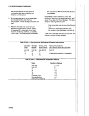
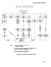
... used with the various methods of telecommunications link, that data collection can continue uninterrupted. 2. TABLE OV5-1. Bring a storage device to the datalogger is reallocated (Section 1.5) - 21X MICROLOGGER OVERVIEW and exchanged for IBM PCIXTIATIPS-2's and compatibles. memory is turned off. Data Retrieval Methods and Related lnstructions TCaaspseette Storage Module *In4st. 96 *8 Inst. 96...
... used with the various methods of telecommunications link, that data collection can continue uninterrupted. 2. TABLE OV5-1. Bring a storage device to the datalogger is reallocated (Section 1.5) - 21X MICROLOGGER OVERVIEW and exchanged for IBM PCIXTIATIPS-2's and compatibles. memory is turned off. Data Retrieval Methods and Related lnstructions TCaaspseette Storage Module *In4st. 96 *8 Inst. 96...
21X Micrologger
Page 25
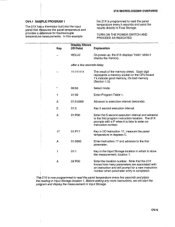
... USER TO VIEW OATA IN ALSO BUFFERS RNAL STORAGE OATA ANO IIRITES IT TO INPUT CASSETTE TAPE. PRINTER OR STORAGE Mq)ULE. 5. THE DSP4 STORAGE. 21X MICROLOGGER OVERVIEW DATA RETRIEVAL DATALOGGER H €!9o'cg I b te OO gf U -oF Eo ge o GU "3 I €SO25ENPIIIRNCRSR-S2_52252COINNTNEERCFTAOCRE.S FIGURE OV$l. I EE P5{) RAOIO IRANSCEI\ER W,/ANTENNA...
... USER TO VIEW OATA IN ALSO BUFFERS RNAL STORAGE OATA ANO IIRITES IT TO INPUT CASSETTE TAPE. PRINTER OR STORAGE Mq)ULE. 5. THE DSP4 STORAGE. 21X MICROLOGGER OVERVIEW DATA RETRIEVAL DATALOGGER H €!9o'cg I b te OO gf U -oF Eo ge o GU "3 I €SO25ENPIIIRNCRSR-S2_52252COINNTNEERCFTAOCRE.S FIGURE OV$l. I EE P5{) RAOIO IRANSCEI\ER W,/ANTENNA...
21X Micrologger
Page 26
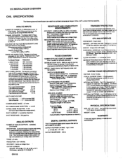
... bat 3ti0s. 2rx Final iromory TE: System u9 to 80 Hz rs possrore Ounng red by thc me exlernal Dat- up to multipler into lour 21X singllended channels. INPUT CURREIIT: 2 nanoatnps ma.ltmum. RAI{GE: i5 vdt3. RESOLUTIOI{: 0.67 millivolE. Continr.ro.E:_ latno @ +V, 5 mA @ -V. ...: 20 V RlrS. t i/tAXIMUM PROGRAM E lasl(s iniiabd an lyncwllh Ons measrrcment wi't dall f|ig rate wl'loul InterrupDon. PHYSICAL SIZE: E.? 21X MICROLOGGER OVERVIEW OV6. Eacfi dilleren0al channol can oe me &hing bridlp tesi!- CHANNEL EXPANSION: The f&del Al,L16 Relav Multigleret allows atl edditionet 64 sineb-end...
... bat 3ti0s. 2rx Final iromory TE: System u9 to 80 Hz rs possrore Ounng red by thc me exlernal Dat- up to multipler into lour 21X singllended channels. INPUT CURREIIT: 2 nanoatnps ma.ltmum. RAI{GE: i5 vdt3. RESOLUTIOI{: 0.67 millivolE. Continr.ro.E:_ latno @ +V, 5 mA @ -V. ...: 20 V RlrS. t i/tAXIMUM PROGRAM E lasl(s iniiabd an lyncwllh Ons measrrcment wi't dall f|ig rate wl'loul InterrupDon. PHYSICAL SIZE: E.? 21X MICROLOGGER OVERVIEW OV6. Eacfi dilleren0al channol can oe me &hing bridlp tesi!- CHANNEL EXPANSION: The f&del Al,L16 Relav Multigleret allows atl edditionet 64 sineb-end...
21X Micrologger
Page 175
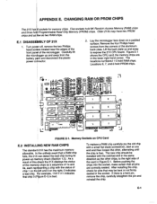
...front pan$l of the memoil chips as the other , alternating until the chip is bad. Lay the micrologger face down on CPU Card E,2 INSTALLING NEW RAM CHIPS The standard 21X has the maximum memory allowable. Figure E-l shows the CPU card; the memory chips are conectly seated. As... a iesult of this OhecktheZlXdisplays the status of the micrologger. Before pushing the chips into the socket, make certain that chip...
...front pan$l of the memoil chips as the other , alternating until the chip is bad. Lay the micrologger face down on CPU Card E,2 INSTALLING NEW RAM CHIPS The standard 21X has the maximum memory allowable. Figure E-l shows the CPU card; the memory chips are conectly seated. As... a iesult of this OhecktheZlXdisplays the status of the micrologger. Before pushing the chips into the socket, make certain that chip...
21X Micrologger
Page 182
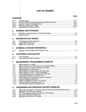
I E$mple of 21X Printable ASCII Output Format....... gWFuVirlVliniBrgeridDHgiaaelgf SrBacrmhidegfmoeraUtFicsuellfdoBrtro1id0Mg0eeoaPhsrmuersePsu1Rr0e0TTo.hr.ma..nPsRdTuc..e..r....... OV-17 2. LyFimeter Weighing Mechanism ...25 and 1.25 Hz Signal.... .....'.. 8-11 8-11 ulated Ocean Buoy FFT Results '....".8-14 LF.1 LIST OF FIGURES PAGE O"tV=1r-"1,=21L[ Micrologger........... I EXTdRNAL STORAGE PERIPHERALS 4.5-1 I 6. 9 PIT| SERIAL INPUT/OUTPUT 6.1-1 6.5-1 9TrFqninsmCittoinng nthee cAStoCIrI .C..h.a.r.a.c.t.e.r.1 3-4 ..'....3-5 3-5 '.'.4-7 .....'.'..6-1 6-4 7....
I E$mple of 21X Printable ASCII Output Format....... gWFuVirlVliniBrgeridDHgiaaelgf SrBacrmhidegfmoeraUtFicsuellfdoBrtro1id0Mg0eeoaPhsrmuersePsu1Rr0e0TTo.hr.ma..nPsRdTuc..e..r....... OV-17 2. LyFimeter Weighing Mechanism ...25 and 1.25 Hz Signal.... .....'.. 8-11 8-11 ulated Ocean Buoy FFT Results '....".8-14 LF.1 LIST OF FIGURES PAGE O"tV=1r-"1,=21L[ Micrologger........... I EXTdRNAL STORAGE PERIPHERALS 4.5-1 I 6. 9 PIT| SERIAL INPUT/OUTPUT 6.1-1 6.5-1 9TrFqninsmCittoinng nthee cAStoCIrI .C..h.a.r.a.c.t.e.r.1 3-4 ..'....3-5 3-5 '.'.4-7 .....'.'..6-1 6-4 7....