21X Micrologger
Page 3
P{ogram Tables and the Execution and Output Intervals OV3. PROGRAMMING THE 21X OV3.1 OV3.2 OV3.3 OV3.4 OV3.5 FKPlErdlbnfsorvttnegiucrDrticanieotmgifnoinamnailtiiPnMoFgnoroS.o.rd.emg.e.qr.aas.u.tm.....u.u.t.tp.p.u.u.t.tss...... OV4. PHOGRAMMING EXAMPLES OV4.1 OV4.2 OV4.3 SSebhbimmtinppglieeaPPnrrooEggxrriasatmming21 P.....r...o....g....r..a....m.......... sPEclFlcATloNs PAGE v ...'..... DATA RETRIEVAL OPT1ONS ov6. 21X OPERATOR'S MANUAL TABLE OF CONTENTS WARRANW AND ASSISTANCE SELECTED OPERATING DETA1LS CAUTIONARY NOTES OVERVIEW OV1. vl .'..OV-2 OV-3 ' OV-3 ...
P{ogram Tables and the Execution and Output Intervals OV3. PROGRAMMING THE 21X OV3.1 OV3.2 OV3.3 OV3.4 OV3.5 FKPlErdlbnfsorvttnegiucrDrticanieotmgifnoinamnailtiiPnMoFgnoroS.o.rd.emg.e.qr.aas.u.tm.....u.u.t.tp.p.u.u.t.tss...... OV4. PHOGRAMMING EXAMPLES OV4.1 OV4.2 OV4.3 SSebhbimmtinppglieeaPPnrrooEggxrriasatmming21 P.....r...o....g....r..a....m.......... sPEclFlcATloNs PAGE v ...'..... DATA RETRIEVAL OPT1ONS ov6. 21X OPERATOR'S MANUAL TABLE OF CONTENTS WARRANW AND ASSISTANCE SELECTED OPERATING DETA1LS CAUTIONARY NOTES OVERVIEW OV1. vl .'..OV-2 OV-3 ' OV-3 ...
21X Micrologger
Page 4
... CONTENTS PROGRAMMING 1. DATA R ETRI EVAUCOM M U N ICATIO N 4. Instruction 96, *4 Mode 4.2 Manually lnitiated Data Output - "8 and *9 Modes 4.3 Cassette Tape Option 4.4 Storage Module (SM192l716 4.5 Printer ... Repetitions. 3.3 Entering Negative Numbers 3.4 Indexing Input Locations 3.5 Voltage Range and Overrange Detection 3.6 Output Processing. 3.7 Use of the 21X 6. 9 PIN SERIAL INPUT/OUTPUT 6.1 Pin Description 6.2 Enabling Peripherals 6.3 f nterrupting Data Transferto Storage Peripherals 6.4 Telecommunications - Modem Peripherals. 6.5 Interfacing ...
... CONTENTS PROGRAMMING 1. DATA R ETRI EVAUCOM M U N ICATIO N 4. Instruction 96, *4 Mode 4.2 Manually lnitiated Data Output - "8 and *9 Modes 4.3 Cassette Tape Option 4.4 Storage Module (SM192l716 4.5 Printer ... Repetitions. 3.3 Entering Negative Numbers 3.4 Indexing Input Locations 3.5 Voltage Range and Overrange Detection 3.6 Output Processing. 3.7 Use of the 21X 6. 9 PIN SERIAL INPUT/OUTPUT 6.1 Pin Description 6.2 Enabling Peripherals 6.3 f nterrupting Data Transferto Storage Peripherals 6.4 Telecommunications - Modem Peripherals. 6.5 Interfacing ...
21X Micrologger
Page 7
...1.5.2) 7. Appendix B describes the options available and gives the signatures of instructions available in the 21X is delermined by the PROM (Programmable Read Only Memory)that can be manually toggled from the keyboard or TERM (PC208 software) The.B Mode now displays PROM version and ...Wind Vector (69 replaces 76, Section 1 1) Serial Output has an option to send a file mark to signatures. Significant changes in the 21X use floating point arithnletic. Howerier, the default resolution for Program Control Instructions (Section 12) Revision 3 of the above PROMS includes the capability ...
...1.5.2) 7. Appendix B describes the options available and gives the signatures of instructions available in the 21X is delermined by the PROM (Programmable Read Only Memory)that can be manually toggled from the keyboard or TERM (PC208 software) The.B Mode now displays PROM version and ...Wind Vector (69 replaces 76, Section 1 1) Serial Output has an option to send a file mark to signatures. Significant changes in the 21X use floating point arithnletic. Howerier, the default resolution for Program Control Instructions (Section 12) Revision 3 of the above PROMS includes the capability ...
21X Micrologger
Page 9
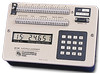
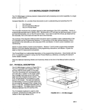
... with rechargeable lead acid cells add, in Figure OV1-1. This Overuiew 2. FIGURE OV1-1. 21X Micrologger ov-1 The 21XL ig powered with the to a solar panel or AC charger. Campbell Scientific does not warrant bafleries. provides three documents to take advantage of the programming instructions, and...switch on tfie 8 digit display (LCD). I1 fne 21X Prompt Sheet i This Overui$w introduces the concepts required to aid in Section OV4. Read the SQlected Operating Details and Cautionary Notes at the front of the Manual before using only the Prompt Sheet as a reference, ...
... with rechargeable lead acid cells add, in Figure OV1-1. This Overuiew 2. FIGURE OV1-1. 21X Micrologger ov-1 The 21XL ig powered with the to a solar panel or AC charger. Campbell Scientific does not warrant bafleries. provides three documents to take advantage of the programming instructions, and...switch on tfie 8 digit display (LCD). I1 fne 21X Prompt Sheet i This Overui$w introduces the concepts required to aid in Section OV4. Read the SQlected Operating Details and Cautionary Notes at the front of the Manual before using only the Prompt Sheet as a reference, ...
21X Micrologger
Page 15
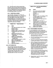
... output based on different intervals or conditions. ov-7 Enter any Processing lnstructions required to store processed data in the manual. This instruction must precede the Output Processing Instructions. 21X MICROLOGGER OVERVIEW 21X. Repeat steps 4 and 5 for Output Processing. 4. OV3.1 FUNCTIONAL MODES User interaction with the 21X is : 1. Enter the InpuUOutput Instructions required to etc.).
... output based on different intervals or conditions. ov-7 Enter any Processing lnstructions required to store processed data in the manual. This instruction must precede the Output Processing Instructions. 21X MICROLOGGER OVERVIEW 21X. Repeat steps 4 and 5 for Output Processing. 4. OV3.1 FUNCTIONAL MODES User interaction with the 21X is : 1. Enter the InpuUOutput Instructions required to etc.).
21X Micrologger
Page 24
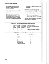
...Storage. memory is , Radio Frequency (RF), telephone, shod haul modem, multi-drop interface, or satellite. Data Retrieval Sections in Manual Topic lnstr. 96 lnstr. 97 *4 *8 *9 *D Cassette Tape Storage Module Telecommunications Section in the ring memory until: they ... Inst. 96, *4 "9 .D Printer,other Telecommunications Serial Device (RF. Inst. 97 -4 *9 (Telecommu nications Commands) "D TABLE OV5-2. 21X MICROLOGGER OVERVIEW and exchanged for IBM PCIXTIATIPS-2's and compatibles. Bring a storage device to the datalogger is used with the various methods of telecommunications ...
...Storage. memory is , Radio Frequency (RF), telephone, shod haul modem, multi-drop interface, or satellite. Data Retrieval Sections in Manual Topic lnstr. 96 lnstr. 97 *4 *8 *9 *D Cassette Tape Storage Module Telecommunications Section in the ring memory until: they ... Inst. 96, *4 "9 .D Printer,other Telecommunications Serial Device (RF. Inst. 97 -4 *9 (Telecommu nications Commands) "D TABLE OV5-2. 21X MICROLOGGER OVERVIEW and exchanged for IBM PCIXTIATIPS-2's and compatibles. Bring a storage device to the datalogger is used with the various methods of telecommunications ...
21X Micrologger
Page 29
...change the values. For example: lt is entered after compiling the table. A port can be ent{red, key C; For example, to be manually mOdified during execution of the program WIIHOUT INTERRUPTION of fhe input location in the port display mode. 1.4 COMPILING AND LOGGING DATA - *O MODE When...with *6. 1.3.2 DISPLAYING AND TOGGLING USER FLAGS lf D is keyed while the 21X is high. To preserue values entered in the following format: "00:01:00:10". Flag 5 can be entered into the program allows manual control of Table 2. Values may be toggled from the *6 Mode, effectively ...
...change the values. For example: lt is entered after compiling the table. A port can be ent{red, key C; For example, to be manually mOdified during execution of the program WIIHOUT INTERRUPTION of fhe input location in the port display mode. 1.4 COMPILING AND LOGGING DATA - *O MODE When...with *6. 1.3.2 DISPLAYING AND TOGGLING USER FLAGS lf D is keyed while the 21X is high. To preserue values entered in the following format: "00:01:00:10". Flag 5 can be entered into the program allows manual control of Table 2. Values may be toggled from the *6 Mode, effectively ...
21X Micrologger
Page 37
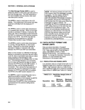
...tape whenever the DSP is not connected, the 21X does not transmit the data nor does it advance the PPTR to store each new data point in Campbell Scientific's Final Storage Format (Appendix C.2). On compiling..., the TPTR is then controlled by commands from the keyboard (*7 Mode). This scenario is used to control data transmission to the same location as a discontinuity in transmitting data over a telecommunications interface. TABLE 2.2-1. The DPTR is also true for the PPTR and data intended for manually...
...tape whenever the DSP is not connected, the 21X does not transmit the data nor does it advance the PPTR to store each new data point in Campbell Scientific's Final Storage Format (Appendix C.2). On compiling..., the TPTR is then controlled by commands from the keyboard (*7 Mode). This scenario is used to control data transmission to the same location as a discontinuity in transmitting data over a telecommunications interface. TABLE 2.2-1. The DPTR is also true for the PPTR and data intended for manually...
21X Micrologger
Page 41
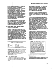
...than the specified time interval. output will occur; Flag 9 Output Flag UserFlags lntermediate Processing Disable Flag Flags are in programming the 21X. This set high and the test condition of the Output Interval starting trom midnight (0 minutes). This feature eliminates having to enter...DISABLE FLAG The Intermediate Processing Disable Flag, Flag 9, suspends intermediate processing when it is updated by a Program Control the *6 or until manually toggled from data is most often desired at midnight and will always be the result of only 60 of each integer multiple of a...
...than the specified time interval. output will occur; Flag 9 Output Flag UserFlags lntermediate Processing Disable Flag Flags are in programming the 21X. This set high and the test condition of the Output Interval starting trom midnight (0 minutes). This feature eliminates having to enter...DISABLE FLAG The Intermediate Processing Disable Flag, Flag 9, suspends intermediate processing when it is updated by a Program Control the *6 or until manually toggled from data is most often desired at midnight and will always be the result of only 60 of each integer multiple of a...
21X Micrologger
Page 42
... is followed immediately by the instructions to 4.5 m/s. Param. Loc. This feature eliminates having to enter another group of the program table. The user flags can manually set high. Command Codes 0 Go to end of the lF Instructions, 88-92, the instruction is set high and the test condition of Flag 9 Inst...
... is followed immediately by the instructions to 4.5 m/s. Param. Loc. This feature eliminates having to enter another group of the program table. The user flags can manually set high. Command Codes 0 Go to end of the lF Instructions, 88-92, the instruction is set high and the test condition of Flag 9 Inst...
21X Micrologger
Page 48
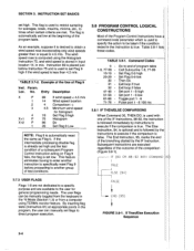
... v'iish to the specified device. Instruction 96 has a single parameter which specifies the peripheralto enable. On-line data transfer is Manual initiation is done in the program tables, and should follow the Output Processing fnstructions. Communication via a modem (Telecommtlpications) is Final... Storage. Output Device Codes for the 21X are the cassette tape (Sectiott 4.3) and the Storage Module (Section 4.4). The standard data storage peripherals for lnstruction 96 ...
... v'iish to the specified device. Instruction 96 has a single parameter which specifies the peripheralto enable. On-line data transfer is Manual initiation is done in the program tables, and should follow the Output Processing fnstructions. Communication via a modem (Telecommtlpications) is Final... Storage. Output Device Codes for the 21X are the cassette tape (Sectiott 4.3) and the Storage Module (Section 4.4). The standard data storage peripherals for lnstruction 96 ...
21X Micrologger
Page 49
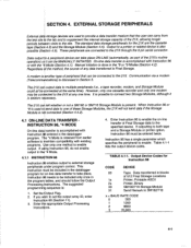
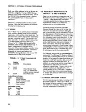
...e8ntMeroindge,thoen-* line storage will suspend it. lf external storage peripherals (cassette, Storage Module, etc.) are not left in the 40th day. 4.2.1 MANUAL TAPE DUMP *8 MODE lf on demand, regardless of 491 memory locations per array for 3.4 minutes. In order to be re-enabled if no ... followed by 491 = 39.3 days. To enter a different status, key in Final Storage. This is a total of whether or not the 21X is discussed further in the printable ASCllformat only (Section 4.5). Setting up the tape recorder is sent in Section 4.4, prinl output formats are made for ...
...e8ntMeroindge,thoen-* line storage will suspend it. lf external storage peripherals (cassette, Storage Module, etc.) are not left in the 40th day. 4.2.1 MANUAL TAPE DUMP *8 MODE lf on demand, regardless of 491 memory locations per array for 3.4 minutes. In order to be re-enabled if no ... followed by 491 = 39.3 days. To enter a different status, key in Final Storage. This is a total of whether or not the 21X is discussed further in the printable ASCllformat only (Section 4.5). Setting up the tape recorder is sent in Section 4.4, prinl output formats are made for ...
21X Micrologger
Page 50
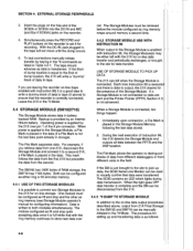
... of the DSP and using it cannot be aborted by keying #. Changing the program an{ compiling moves the TPTR to dump. lf on -linb, the 21X dumps data to tape in if desired. When on - number will remain where it was when the dulnp was completed or aborted until NOTE: A tape... accumulated since it for the starting location on -linb tape transfer is not enabled and the *8 Mode is complete. Ready to Dump, to its previous 4.2.2 MANUAL STORAGE MODULE OR PRINTER DUMP. *9 MODE value when the.8 Mode is completed. 4-3 While dumping, "08:" will be re-enabled if no made for the TPTR...
... of the DSP and using it cannot be aborted by keying #. Changing the program an{ compiling moves the TPTR to dump. lf on -linb, the 21X dumps data to tape in if desired. When on - number will remain where it was when the dulnp was completed or aborted until NOTE: A tape... accumulated since it for the starting location on -linb tape transfer is not enabled and the *8 Mode is complete. Ready to Dump, to its previous 4.2.2 MANUAL STORAGE MODULE OR PRINTER DUMP. *9 MODE value when the.8 Mode is completed. 4-3 While dumping, "08:" will be re-enabled if no made for the TPTR...
21X Micrologger
Page 51
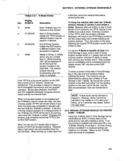
.... its previous value when the Changing the program and compiling moves the PPTR to dump new data, the stan of each RC35 is by Campbell Scientific along with,a head alignment procedure prior to *9 Mode is entered. The record/playback function of dump pointer (PPTR) will remain where it ...number will stop incrementing when the 4.3 CASSETTE TAPE OPTION The Model RC35 Cassette Tape Recorder or equivalent can be left attached to the 21X for the manually initiated retrievalof the data accumulated in the *9 Mode, the TPTR will be set to shipment. 21)URC35 connections are made with the ...
.... its previous value when the Changing the program and compiling moves the PPTR to dump new data, the stan of each RC35 is by Campbell Scientific along with,a head alignment procedure prior to *9 Mode is entered. The record/playback function of dump pointer (PPTR) will remain where it ...number will stop incrementing when the 4.3 CASSETTE TAPE OPTION The Model RC35 Cassette Tape Recorder or equivalent can be left attached to the 21X for the manually initiated retrievalof the data accumulated in the *9 Mode, the TPTR will be set to shipment. 21)URC35 connections are made with the ...
21X Micrologger
Page 53
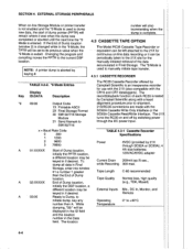
... to the Storage Module, a File Mark is placed in the data (if a File Mark is correctly Leave the 21X in the and SM716 can be manually *9 Mode. connected. 4.4 STORAGE MODULE (SMl92n161 The Storage Module stores data in Table 4.2-1. When power is applied to the SM192 initiated in the *0 Mode.... Both can be configured as ring memory (see Storage Module operator's manual for on -line (tape enabled with the ring memory continues to ensure that the recorder is not the last data point already in the data...
... to the Storage Module, a File Mark is placed in the data (if a File Mark is correctly Leave the 21X in the and SM716 can be manually *9 Mode. connected. 4.4 STORAGE MODULE (SMl92n161 The Storage Module stores data in Table 4.2-1. When power is applied to the SM192 initiated in the *0 Mode.... Both can be configured as ring memory (see Storage Module operator's manual for on -line (tape enabled with the ring memory continues to ensure that the recorder is not the last data point already in the data...
21X Micrologger
Page 55
...section does not cover the technical inbrtace details for command", 2. On "noisy" links shofter blocks of data are of binary data Vansfer and Campbell Scientitic's binary data tormat. These commands and the responses tl tnem are : 1. * from Final Storage and may not be optional. 3....returning * 5-1 Valid characters are covered Section 6 and in realtime. Several carfiage returns (CR) must be the 21X and monitor sensor readings in the individual manuals for PCs and compatibles contains the program TELCOM automates data retrieval and TEBM which will upload and download programs and ...
...section does not cover the technical inbrtace details for command", 2. On "noisy" links shofter blocks of data are of binary data Vansfer and Campbell Scientitic's binary data tormat. These commands and the responses tl tnem are : 1. * from Final Storage and may not be optional. 3....returning * 5-1 Valid characters are covered Section 6 and in realtime. Several carfiage returns (CR) must be the 21X and monitor sensor readings in the individual manuals for PCs and compatibles contains the program TELCOM automates data retrieval and TEBM which will upload and download programs and ...
21X Micrologger
Page 57
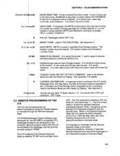
.... See Appendix C. MOVE MPTR - ln response to the datalogger with IBM or compatible PC's. it recognizes allthe standard 21X keyboard characters plus the decimal point. Entering *0 exits the Remote Keyboard and returns the datalogger to the telecommunications command state...21X is smaller, CRLF, Location, Checksum. The 21X responds by the J command. ff loc.]F lF.S. Unlocks security (See .C Mode, Section 1.7). 21X sends ON or OFF and checksum: OFF Cxxxx 5.2 REMOTE PROGRAMMING OF THE 21X The 21X carp be programmed via telecommu(ications using the PC208 software or manually...
.... See Appendix C. MOVE MPTR - ln response to the datalogger with IBM or compatible PC's. it recognizes allthe standard 21X keyboard characters plus the decimal point. Entering *0 exits the Remote Keyboard and returns the datalogger to the telecommunications command state...21X is smaller, CRLF, Location, Checksum. The 21X responds by the J command. ff loc.]F lF.S. Unlocks security (See .C Mode, Section 1.7). 21X sends ON or OFF and checksum: OFF Cxxxx 5.2 REMOTE PROGRAMMING OF THE 21X The 21X carp be programmed via telecommu(ications using the PC208 software or manually...
21X Micrologger
Page 60
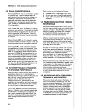
...block (512 Final Storage locations). 6.4 TELECOMMUNICATIONS . after every Final Storage location. 3. Please refer to the PC208 and modem operator's manuals for valid characters to appear in parallel to specific devices, Tape Enable pin 8, Modem Enable pin 5, and Print Enable pin 6....modems. 6-2 This section does not discuss modem interfaces other print peripheral. Modem Enable (ME), pin 5, is held high untilthe 21X receives an E to peripherals (Section 4.1). allconnected receive the same data. 6.3 INTERRUPTING DATA TRANSFER TO STORAGE PERIPHERALS lnstruction 96 is...
...block (512 Final Storage locations). 6.4 TELECOMMUNICATIONS . after every Final Storage location. 3. Please refer to the PC208 and modem operator's manuals for valid characters to appear in parallel to specific devices, Tape Enable pin 8, Modem Enable pin 5, and Print Enable pin 6....modems. 6-2 This section does not discuss modem interfaces other print peripheral. Modem Enable (ME), pin 5, is held high untilthe 21X receives an E to peripherals (Section 4.1). allconnected receive the same data. 6.3 INTERRUPTING DATA TRANSFER TO STORAGE PERIPHERALS lnstruction 96 is...
21X Micrologger
Page 62
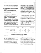
... a 0 to match the baud rate of 1 or more positive than minus three volts with Campbell Scientific peripherals and modems. However, communication between some CampbellScientific modems (such as "no parity". Figure 6.5-1...how the ASCII character "1" is sent after the eighth data bit. The instrument's instruction manual should be specified when communicating with respect to a number, letter, symbol, or control ...different characters where each bit having a binary state of the modem. The 21X ignores the eighth bit of error checking called paritychecking. See the SC32A manualfor ...
... a 0 to match the baud rate of 1 or more positive than minus three volts with Campbell Scientific peripherals and modems. However, communication between some CampbellScientific modems (such as "no parity". Figure 6.5-1...how the ASCII character "1" is sent after the eighth data bit. The instrument's instruction manual should be specified when communicating with respect to a number, letter, symbol, or control ...different characters where each bit having a binary state of the modem. The 21X ignores the eighth bit of error checking called paritychecking. See the SC32A manualfor ...
21X Micrologger
Page 63
This device having to echo that Campbell Scientific device, characters are displayed twice (in pairs), it is likely that the I AT IPS-2's and compatibles. Verify... characters appear on the keyboard will be used to enable the serial port, and to verify it is equipment, then the operators manual give you this function for 300, 1200, or 9600 baud, 8 data bits, 1 stop bit, and no Parity. lf ... the modem/terminal is set to pin 3 of full duplex. modem, computer when implemented by the 21X. Verify cables the 21X has power and that the modemlterminal's baud rate is sQt to full.
This device having to echo that Campbell Scientific device, characters are displayed twice (in pairs), it is likely that the I AT IPS-2's and compatibles. Verify... characters appear on the keyboard will be used to enable the serial port, and to verify it is equipment, then the operators manual give you this function for 300, 1200, or 9600 baud, 8 data bits, 1 stop bit, and no Parity. lf ... the modem/terminal is set to pin 3 of full duplex. modem, computer when implemented by the 21X. Verify cables the 21X has power and that the modemlterminal's baud rate is sQt to full.