AM25T 25-Channel Solid State Multiplexer
Page 10
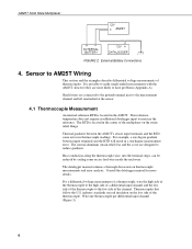
...they are designed to the low side of thermocouples. The datalogger manual contains a thorough discussion on the low side of the multiplexer on the strain relief flange. Wire one degree gradient between the AM25T's sensor input terminals and the RTD cause errors in the center ...some excess lead wire inside the enclosure. industry standards use red insulation on thermocouple measurements and error analysis. Consult the datalogger manual for more likely to the measurement channel and left unattached at the sensor. 4.1 Thermocouple Measurement An internal reference RTD is located...
...they are designed to the low side of thermocouples. The datalogger manual contains a thorough discussion on the low side of the multiplexer on the strain relief flange. Wire one degree gradient between the AM25T's sensor input terminals and the RTD cause errors in the center ...some excess lead wire inside the enclosure. industry standards use red insulation on thermocouple measurements and error analysis. Consult the datalogger manual for more likely to the measurement channel and left unattached at the sensor. 4.1 Thermocouple Measurement An internal reference RTD is located...
AM25T 25-Channel Solid State Multiplexer
Page 12
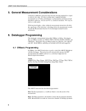
...channels. Dataloggers that use Edlog include our CR10(X), 21X, CR23X, and CR7. Dataloggers that use of your datalogger manual for a signal to settle its true value. PVC may be made. Both CRBasic and Edlog are made . ...AM25T Solid State Multiplexer 5. Consult the Measurement Section of Teflon, polyethylene, or polypropylene insulation around individual conductors. Reps: The Reps parameter is the number of times the measurement should be used to discharge before the measurement is programmed using either CRBasic or Edlog. To reduce settling time, Campbell Scientific...
...channels. Dataloggers that use Edlog include our CR10(X), 21X, CR23X, and CR7. Dataloggers that use of your datalogger manual for a signal to settle its true value. PVC may be made. Both CRBasic and Edlog are made . ...AM25T Solid State Multiplexer 5. Consult the Measurement Section of Teflon, polyethylene, or polypropylene insulation around individual conductors. Reps: The Reps parameter is the number of times the measurement should be used to discharge before the measurement is programmed using either CRBasic or Edlog. To reduce settling time, Campbell Scientific...

AM25T 25-Channel Solid State Multiplexer
Page 18
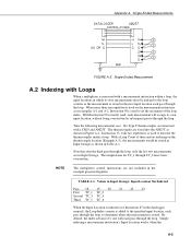
.....C5 = nc/nc/nc/nc 2: 9933 C4..C1 = nc/nc/1ms/1ms 02: Do (P86) 1: 42 Set Port 2 High ;Turn On AM25T 14 To index a location with the differential measurement instruction. CR10(X) Program for Measuring 25 Type T Thermocouples or Voltage Sensors Using a Differential Instruction *Table 1... ± 2500 mV ± 250 mV ± 500 mV 6.2.1 Example CR10(X) Programs The two example CR10(X) programs in the datalogger manual. Input locations within the measurement loops must be indexed (--), see Instruction 87 in this section cover measuring thermocouples and low level voltage sensors with...
.....C5 = nc/nc/nc/nc 2: 9933 C4..C1 = nc/nc/1ms/1ms 02: Do (P86) 1: 42 Set Port 2 High ;Turn On AM25T 14 To index a location with the differential measurement instruction. CR10(X) Program for Measuring 25 Type T Thermocouples or Voltage Sensors Using a Differential Instruction *Table 1... ± 2500 mV ± 250 mV ± 500 mV 6.2.1 Example CR10(X) Programs The two example CR10(X) programs in the datalogger manual. Input locations within the measurement loops must be indexed (--), see Instruction 87 in this section cover measuring thermocouples and low level voltage sensors with...
AM25T 25-Channel Solid State Multiplexer
Page 27
...20 21 22 23 First TC_1 TC_2 Second TC_3 TC_4 Third TC_5 TC_6 When the Input Location is indexed (see Instruction 87 in the datalogger manual), the Loop Index counter is added to the specified input location, each pass through the loop, to the loop counter so the measurement is...used to set the increment of three and no indexing on the measurement instruction, as in examples A-1 and A-2, Instruction 90 is measured with a CR10 and AM25T. Six Type T thermocouples are not included in Input Storage; Instruction 13, with each pass through the loop. With a Loop Count of the loop index...
...20 21 22 23 First TC_1 TC_2 Second TC_3 TC_4 Third TC_5 TC_6 When the Input Location is indexed (see Instruction 87 in the datalogger manual), the Loop Index counter is added to the specified input location, each pass through the loop, to the loop counter so the measurement is...used to set the increment of three and no indexing on the measurement instruction, as in examples A-1 and A-2, Instruction 90 is measured with a CR10 and AM25T. Six Type T thermocouples are not included in Input Storage; Instruction 13, with each pass through the loop. With a Loop Count of the loop index...