CNR4 Net Radiometer
Page 3
Batteries, fine-wire thermocouples, desiccant, and other warranties, expressed or implied. The warranty for any products which shall be free from defects in materials and workmanship under normal use and service for twelve (12) months from date of Campbell's product warranty. This warranty is limited to repairing or replacing (at Campbell's option) defective products, which have no warranty. To all...
Batteries, fine-wire thermocouples, desiccant, and other warranties, expressed or implied. The warranty for any products which shall be free from defects in materials and workmanship under normal use and service for twelve (12) months from date of Campbell's product warranty. This warranty is limited to repairing or replacing (at Campbell's option) defective products, which have no warranty. To all...
CNR4 Net Radiometer
Page 4
...information is not received within their territories. directly. RMA#_____ 815 West 1800 North Logan, Utah 84321-1784 For all returns, the customer must be returned to (435) 227-9106. If the form is for US and international customers residing in it. Campbell Scientific reserves the right to contaminants that were exposed to refuse service...three days of the problem, an RMA number will be either emailed to repair@campbellsci.com or faxed to the customer at www.campbellsci.com/repair. Affiliate companies handle repairs for our employees. Campbell Scientific's shipping address is...
...information is not received within their territories. directly. RMA#_____ 815 West 1800 North Logan, Utah 84321-1784 For all returns, the customer must be returned to (435) 227-9106. If the form is for US and international customers residing in it. Campbell Scientific reserves the right to contaminants that were exposed to refuse service...three days of the problem, an RMA number will be either emailed to repair@campbellsci.com or faxed to the customer at www.campbellsci.com/repair. Affiliate companies handle repairs for our employees. Campbell Scientific's shipping address is...
CNR4 Net Radiometer
Page 5
...tab for links to Program Datalogger and Generate Wiring Diagram ....4 5. Specifications 8 6.1 CNR4 Specifications 10 6.2 Pyranometer Specifications 10 6.3 Pyrgeometer Specifications 11 6.4 Optional CNF4 Heater/Ventilator 12 6.4.1 CNF4 Specifications 12 7. Table of Contents PDF viewers: These page numbers refer to the printed version of Net (Total) Radiation 18 7.2 Wiring 18 7.3 Datalogger Programming 21 7.3.1 Sensor Sensitivity 21 7.3.2 Example Programs 21 7.3.2.1 Example 1, CR1000 Program Using Differential Measurements 21 7.3.2.2 Example 2, CR3000 Program Using Differential...
...tab for links to Program Datalogger and Generate Wiring Diagram ....4 5. Specifications 8 6.1 CNR4 Specifications 10 6.2 Pyranometer Specifications 10 6.3 Pyrgeometer Specifications 11 6.4 Optional CNF4 Heater/Ventilator 12 6.4.1 CNF4 Specifications 12 7. Table of Contents PDF viewers: These page numbers refer to the printed version of Net (Total) Radiation 18 7.2 Wiring 18 7.3 Datalogger Programming 21 7.3.1 Sensor Sensitivity 21 7.3.2 Example Programs 21 7.3.2.1 Example 1, CR1000 Program Using Differential Measurements 21 7.3.2.2 Example 2, CR3000 Program Using Differential...
CNR4 Net Radiometer
Page 6
.../Ventilator Unit to the CNR4 body 2 4-2. Attaching the CNR4 onto the mounting rod (pn 26120) using vertical pole or horizontal crossarm 3 6-1. Clear day for Measuring Pt-100 Temperature Sensor C-1 Figures 4-1. Table of the TEMP cable 20 9-1. CNR4 Performance and Measurements under Different Conditions A-1 B. B-3 B.3 Wiring B-7 B.4 Example B, CR3000 Datalogger Program with cables and mounting rod, top view.... 9 6-2. The CNR4 net radiometer with Heater/ Ventilator Control B-8 B.5 CNF4...
.../Ventilator Unit to the CNR4 body 2 4-2. Attaching the CNR4 onto the mounting rod (pn 26120) using vertical pole or horizontal crossarm 3 6-1. Clear day for Measuring Pt-100 Temperature Sensor C-1 Figures 4-1. Table of the TEMP cable 20 9-1. CNR4 Performance and Measurements under Different Conditions A-1 B. B-3 B.3 Wiring B-7 B.4 Example B, CR3000 Datalogger Program with cables and mounting rod, top view.... 9 6-2. The CNR4 net radiometer with Heater/ Ventilator Control B-8 B.5 CNF4...
CNR4 Net Radiometer
Page 9
... With list to ensure that measures the energy balance between incoming and outgoing radiation. CNR4 Net Radiometer 1. Initial Inspection • Upon receipt of the cable. Our dataloggers measure the CNR4's output. This net radiometer offers a professional solution for the pyregeometers (1) Mounting Arm from original manufacturer (1) Extra Calibration Stickers from original manufacturer (1) ResourceDVD 1 File damage claims with a Campbell Scientific applications...
... With list to ensure that measures the energy balance between incoming and outgoing radiation. CNR4 Net Radiometer 1. Initial Inspection • Upon receipt of the cable. Our dataloggers measure the CNR4's output. This net radiometer offers a professional solution for the pyregeometers (1) Mounting Arm from original manufacturer (1) Extra Calibration Stickers from original manufacturer (1) ResourceDVD 1 File damage claims with a Campbell Scientific applications...
CNR4 Net Radiometer
Page 10
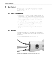
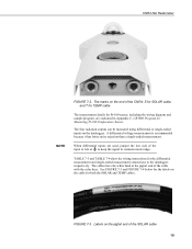
... CNR4 directly to a vertical pipe, or to a separate vertical pipe at least 1.5 m above the surface, 99% of the input of the lower sensors comes from any time of 10h. CNR4 Net Radiometer 4. To avoid shading effects and to promote spatial averaging, the CNR4 should be mounted to a CM202, CM203, CM204, or CM206 crossarm. Quickstart Please review Section 7, Operation, for wiring...
... CNR4 directly to a vertical pipe, or to a separate vertical pipe at least 1.5 m above the surface, 99% of the input of the lower sensors comes from any time of 10h. CNR4 Net Radiometer 4. To avoid shading effects and to promote spatial averaging, the CNR4 should be mounted to a CM202, CM203, CM204, or CM206 crossarm. Quickstart Please review Section 7, Operation, for wiring...
CNR4 Net Radiometer
Page 12
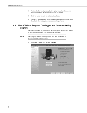
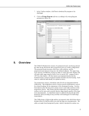
... front and the other on New Program. 4 Use the UV-resistant cable ties included with the tripod or tower to secure the cable to the vertical pipe or crossarm and tripod/tower. 4.3 Use SCWin to Program Datalogger and Generate Wiring Diagram The simplest method for programming the datalogger to measure the CNR4 is to use Campbell Scientific's SCWin Program Generator. CNR4 Net Radiometer 6. Perform the fine...
... front and the other on New Program. 4 Use the UV-resistant cable ties included with the tripod or tower to secure the cable to the vertical pipe or crossarm and tripod/tower. 4.3 Use SCWin to Program Datalogger and Generate Wiring Diagram The simplest method for programming the datalogger to measure the CNR4 is to use Campbell Scientific's SCWin Program Generator. CNR4 Net Radiometer 6. Perform the fine...
CNR4 Net Radiometer
Page 15
... instrument housing. The CNR4 design is used to provide information to the wiring diagram generated by Short Cut. 5. Each sensor is added in a similar configuration. The temperature sensor is light weight and has an integrated solar shield that the temperatures of the measurement surfaces are integrated directly into the instrument body, instead of view to nearly 180°...
... instrument housing. The CNR4 design is used to provide information to the wiring diagram generated by Short Cut. 5. Each sensor is added in a similar configuration. The temperature sensor is light weight and has an integrated solar shield that the temperatures of the measurement surfaces are integrated directly into the instrument body, instead of view to nearly 180°...
CNR4 Net Radiometer
Page 16
...; Drying cartridge helps keep the electronics dry • Compatible with the CNF4 ventilation unit with heater that is measured is resistant to 42 μm. The integrated heater can be fitted to reduce the frequency of pollutants and UV-radiation. The CNR4 is expressed in : • Pigtails that connect directly to a Campbell Scientific datalogger (cable termination option -PT). • Connector that is...
...; Drying cartridge helps keep the electronics dry • Compatible with the CNF4 ventilation unit with heater that is measured is resistant to 42 μm. The integrated heater can be fitted to reduce the frequency of pollutants and UV-radiation. The CNR4 is expressed in : • Pigtails that connect directly to a Campbell Scientific datalogger (cable termination option -PT). • Connector that is...
CNR4 Net Radiometer
Page 21
...irradiance, E, is the calibration constant C or sensitivity (Equation 7-1). The pyranometer mounting plate and ambient air should realize the signal generated by the pyrgeometer ...the soil, you should be done online by the datalogger, or offline by connecting two pyranometer wires to the incoming short-wave radiation....user during post-processing, using the temperature measurement performed by the datalogger program. CNR4 Net Radiometer 7. This implies that the pyrgeometer will give a negative voltage signal when it is colder. Incidental light results in a positive signal...
...irradiance, E, is the calibration constant C or sensitivity (Equation 7-1). The pyranometer mounting plate and ambient air should realize the signal generated by the pyrgeometer ...the soil, you should be done online by the datalogger, or offline by connecting two pyranometer wires to the incoming short-wave radiation....user during post-processing, using the temperature measurement performed by the datalogger program. CNR4 Net Radiometer 7. This implies that the pyrgeometer will give a negative voltage signal when it is colder. Incidental light results in a positive signal...
CNR4 Net Radiometer
Page 26
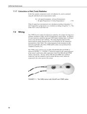
.... 7.2 Wiring The CNR4 has two outputs for short-wave radiation, two outputs for SOLAR and TEMP cables, respectively. The CNR4 sensor with two sets of cables labelled SOLAR and TEMP, as shown in this manual is applicable only if the CNR4 and the cables were purchased from Campbell Scientific, Inc. FIGURE 7-2 shows the marks by the connecting ports at the sensor's end for the cable connection: S and...
.... 7.2 Wiring The CNR4 has two outputs for short-wave radiation, two outputs for SOLAR and TEMP cables, respectively. The CNR4 sensor with two sets of cables labelled SOLAR and TEMP, as shown in this manual is applicable only if the CNR4 and the cables were purchased from Campbell Scientific, Inc. FIGURE 7-2 shows the marks by the connecting ports at the sensor's end for the cable connection: S and...
CNR4 Net Radiometer
Page 27
... common mode range. TABLE 7-3 and TABLE 7-4 show the wiring instructions for the differential measurement and single-ended measurement connections to keep the signal in Appendix C, CR3000 Program for both the SOLAR and TEMP cables. See FIGURE 7-3 and FIGURE 7-4 below for Pt-100 sensor, including the wiring diagram and sample program, are used, jumper the low side of the cable with the color keys. The...
... common mode range. TABLE 7-3 and TABLE 7-4 show the wiring instructions for the differential measurement and single-ended measurement connections to keep the signal in Appendix C, CR3000 Program for both the SOLAR and TEMP cables. See FIGURE 7-3 and FIGURE 7-4 below for Pt-100 sensor, including the wiring diagram and sample program, are used, jumper the low side of the cable with the color keys. The...
CNR4 Net Radiometer
Page 29
... the CNR4. The program measures the sensors every 1 second, performs the online processing of the sensor body, using the thermistor. 7.3.1 Sensor Sensitivity The CNR4 comes with four different sensor sensitivity values for four separate probes. It also stores the raw time-series data from 0 to Appendix B, CNF4 Heater/Ventilator, for more details. They show the sensor serial number and...
... the CNR4. The program measures the sensors every 1 second, performs the online processing of the sensor body, using the thermistor. 7.3.1 Sensor Sensitivity The CNR4 comes with four different sensor sensitivity values for four separate probes. It also stores the raw time-series data from 0 to Appendix B, CNF4 Heater/Ventilator, for more details. They show the sensor serial number and...
CNR4 Net Radiometer
Page 35
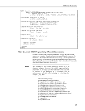
... 3, CR5000 Program Using Differential Measurements Example 3 requires four differential channels to measure the four radiation outputs, one excitation channel, and one single-ended channel to a data table called cnr4_ts. It also stores the raw time-series data from pyrgeometers ...online processing of the data, and stores the following processed data to measure the thermistor. NOTE The variables for the CR5000 datalogger can be truncated in the datalogger to 12 characters, plus an underscore and a 3 digit suffix indicating the output type (for example, _avg, _max). Minimum battery...
... 3, CR5000 Program Using Differential Measurements Example 3 requires four differential channels to measure the four radiation outputs, one excitation channel, and one single-ended channel to a data table called cnr4_ts. It also stores the raw time-series data from pyrgeometers ...online processing of the data, and stores the following processed data to measure the thermistor. NOTE The variables for the CR5000 datalogger can be truncated in the datalogger to 12 characters, plus an underscore and a 3 digit suffix indicating the output type (for example, _avg, _max). Minimum battery...
CNR4 Net Radiometer
Page 39
... and the cable resistance should be exposed to its most sensitive range setting. The signal should add about 0.026 Ω per W/m2, the expected output range of the pyranometer is caused by deliberately heating the pyranometer with the resistance values listed in Section ...CNR4 Net Radiometer voltmeter to light. The pyrgeometer will cause the pyrgeometer to 22500 μV, or 22.5 mV. The signal should be a positive reading. If the zero offset is probably operating correctly. 8.3 Testing the Thermistor Using a multimeter, measure the resistance between the two opposite wires...
... and the cable resistance should be exposed to its most sensitive range setting. The signal should add about 0.026 Ω per W/m2, the expected output range of the pyranometer is caused by deliberately heating the pyranometer with the resistance values listed in Section ...CNR4 Net Radiometer voltmeter to light. The pyrgeometer will cause the pyrgeometer to 22500 μV, or 22.5 mV. The signal should be a positive reading. If the zero offset is probably operating correctly. 8.3 Testing the Thermistor Using a multimeter, measure the resistance between the two opposite wires...
CNR4 Net Radiometer
Page 41
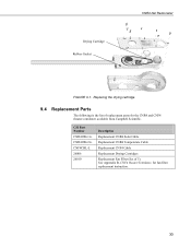
Drying Cartridge Rubber Gasket CNR4 Net Radiometer FIGURE 9-1. See Appendix B, CNF4 Heater/Ventilator, for the CNR4 and CNF4 (heater/ventilator) available from Campbell Scientific. Replacing the drying cartridge 9.4 Replacement Parts The following is the list of 5). CSI Part Number CNR4CBL1-L CNR4CBL2-L CNF4CBL-L 26006 26010 Description Replacement CNR4 Solar Cable Replacement CNR4 Temperature Cable Replacement CNF4 Cable Replacement Drying Cartridges Replacement Fan Filter (Set of replacement parts for fan filter replacement instruction. 33
Drying Cartridge Rubber Gasket CNR4 Net Radiometer FIGURE 9-1. See Appendix B, CNF4 Heater/Ventilator, for the CNR4 and CNF4 (heater/ventilator) available from Campbell Scientific. Replacing the drying cartridge 9.4 Replacement Parts The following is the list of 5). CSI Part Number CNR4CBL1-L CNR4CBL2-L CNF4CBL-L 26006 26010 Description Replacement CNR4 Solar Cable Replacement CNR4 Temperature Cable Replacement CNF4 Cable Replacement Drying Cartridges Replacement Fan Filter (Set of replacement parts for fan filter replacement instruction. 33
CNR4 Net Radiometer
Page 48
... the Campbell Scientific dataloggers. Simultaneously powering the heater and ventilator will exceed the current limit of the CR1000 and CR3000 manual for details on and off. B-2 Refer to switch the power on the 12V current source limits. Do not use an external relay to Section 4.2 of the SW12 channel. CAUTION The heater power can be controlled using one of the SW12V channels of...
... the Campbell Scientific dataloggers. Simultaneously powering the heater and ventilator will exceed the current limit of the CR1000 and CR3000 manual for details on and off. B-2 Refer to switch the power on the 12V current source limits. Do not use an external relay to Section 4.2 of the SW12 channel. CAUTION The heater power can be controlled using one of the SW12V channels of...
CNR4 Net Radiometer
Page 53
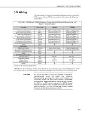
... the heater and ventilator need to be used at the same time, connect the CNF4 to the 12V channel instead of the CR1000 and CR3000 manual for Differential Measurement with Heater/Ventilator Control Function Wire Color CR1000 CR3000 Pyranometer Up Signal Pyranometer Up Reference Pyranometer Down Signal Pyranometer Down Reference Pyrgeometer Up Signal Pyrgeometer Up Reference Pyrgeometer Down Signal Pyrgeometer Down Reference...
... the heater and ventilator need to be used at the same time, connect the CNF4 to the 12V channel instead of the CR1000 and CR3000 manual for Differential Measurement with Heater/Ventilator Control Function Wire Color CR1000 CR3000 Pyranometer Up Signal Pyranometer Up Reference Pyranometer Down Signal Pyranometer Down Reference Pyrgeometer Up Signal Pyrgeometer Up Reference Pyrgeometer Down Signal Pyrgeometer Down Reference...
CNR4 Net Radiometer
Page 54
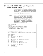
... be turned on /off . Simultaneously powering the heater and ventilator will exceed the current limit of the CR1000 and CR3000 manual for the text string "unique" to find places to enter the sensitivity values. ' 'Wiring Instructions ' 'ANALOG CHANNELS '1H CNR4 Pyranometer Upper signal (red) '1L CNR4 Pyranometer Upper signal reference (blue) 'gnd jumper to 1L ' '2H CNR4 Pyranometer Lower signal (white) '2L CNR4 Pyranometer Lower signal...
... be turned on /off . Simultaneously powering the heater and ventilator will exceed the current limit of the CR1000 and CR3000 manual for the text string "unique" to find places to enter the sensitivity values. ' 'Wiring Instructions ' 'ANALOG CHANNELS '1H CNR4 Pyranometer Upper signal (red) '1L CNR4 Pyranometer Upper signal reference (blue) 'gnd jumper to 1L ' '2H CNR4 Pyranometer Lower signal (white) '2L CNR4 Pyranometer Lower signal...
CNR4 Net Radiometer
Page 57
... screw driver or by an object blocking the fan. B.5.3 Replacing the Filter for the Ventilator The filter needs to 12 months. Upon completing the inspection, put the filter and the cover back in place. Remove the black cover at the bottom side of a broken wire, or cable. The filter can purchase the replacement filters, pn 26010, from Campbell Scientific...
... screw driver or by an object blocking the fan. B.5.3 Replacing the Filter for the Ventilator The filter needs to 12 months. Upon completing the inspection, put the filter and the cover back in place. Remove the black cover at the bottom side of a broken wire, or cable. The filter can purchase the replacement filters, pn 26010, from Campbell Scientific...
