
CR510 Basic Datalogger
Page 6
...Entering Negative Numbers 3-1 3.4 Indexing Input Locations ...3-1 3.5 Voltage Range and Overrange Detection 3-2 3.6 Output Processing...3-2 3.7 Use of the CR510 5-4 6. 9-PIN SERIAL INPUT/OUTPUT 6.1 Pin Description ...6-1 6.2 Enabling and Addressing Peripherals 6-2 6.3 Ring Interrupts...6-3 6.4 Interrupts During Data... EXAMPLES 7. Instruction 96 4-1 4.2 Manually Initiated Data Output - ∗8 Mode 4-3 4.3 Printer Output Formats...4-3 4.4 Storage Module ...4-4 4.5 ∗9 Mode -- SM192/716 Storage Module Commands 4-5 5. CR510 TABLE OF CONTENTS 2.
...Entering Negative Numbers 3-1 3.4 Indexing Input Locations ...3-1 3.5 Voltage Range and Overrange Detection 3-2 3.6 Output Processing...3-2 3.7 Use of the CR510 5-4 6. 9-PIN SERIAL INPUT/OUTPUT 6.1 Pin Description ...6-1 6.2 Enabling and Addressing Peripherals 6-2 6.3 Ring Interrupts...6-3 6.4 Interrupts During Data... EXAMPLES 7. Instruction 96 4-1 4.2 Manually Initiated Data Output - ∗8 Mode 4-3 4.3 Printer Output Formats...4-3 4.4 Storage Module ...4-4 4.5 ∗9 Mode -- SM192/716 Storage Module Commands 4-5 5. CR510 TABLE OF CONTENTS 2.
CR510 Basic Datalogger
Page 8
......F-1 F.2 Communications and Compatibility F-1 F.3 More on Modbus ...F-2 G. TD OPERATING SYSTEM ADDENDUM FOR CR510, CR10X, AND CR23X MANUALS LIST OF TABLES ...LT-1 LIST OF FIGURES ...LF-1 iv ADDITIONAL TELECOMMUNICATIONS INFORMATION B.1 Telecommunications Command with Binary Responses B-1 B.2 Final Storage Format ...B-3 B.3 Generation of Signature ...B-5 B.4 ∗D Commands ...
......F-1 F.2 Communications and Compatibility F-1 F.3 More on Modbus ...F-2 G. TD OPERATING SYSTEM ADDENDUM FOR CR510, CR10X, AND CR23X MANUALS LIST OF TABLES ...LT-1 LIST OF FIGURES ...LF-1 iv ADDITIONAL TELECOMMUNICATIONS INFORMATION B.1 Telecommunications Command with Binary Responses B-1 B.2 Final Storage Format ...B-3 B.3 Generation of Signature ...B-5 B.4 ∗D Commands ...

CR510 Basic Datalogger
Page 13
...battery backed clock in Section OV5. Campbell Scientific Inc. This Overview 2. The CR510 Prompt Sheet 4. Working with a CR510 will help the learning process, so don't just read the rest of options (Section 14) for networks and single logger applications. Once familiar with the CR510, it is external to provide ... program file, Short Cut creates a table to simplify wiring sensors to guide you are : • The CR510 does not have detailed descriptions of the Manual before using only the Prompt Sheet as an independent channel to measure voltage with 1H; Sections 9-12 have an...
...battery backed clock in Section OV5. Campbell Scientific Inc. This Overview 2. The CR510 Prompt Sheet 4. Working with a CR510 will help the learning process, so don't just read the rest of options (Section 14) for networks and single logger applications. Once familiar with the CR510, it is external to provide ... program file, Short Cut creates a table to simplify wiring sensors to guide you are : • The CR510 does not have detailed descriptions of the Manual before using only the Prompt Sheet as an independent channel to measure voltage with 1H; Sections 9-12 have an...
CR510 Basic Datalogger
Page 20
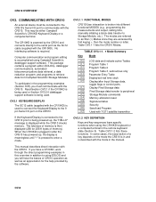
...programming examples (Section OV5) you must be either Campbell Scientific's CR10KD Keyboard Display or a computer/terminal. Table OV3.1-2 lists these functions. COMMUNICATING WITH CR510 An external device must communicate with the CR510. This package contains a program editor (EDLOG),... with the CR10KD) is broken into different functional MODES (e.g., programming the measurements and output, setting time, manually initiating a block data transfer to using Campbell Scientific's datalogger support software. TABLE OV3.1-1. ∗ Mode Summary Key Mode ∗ 0 LOG data and ...
...programming examples (Section OV5) you must be either Campbell Scientific's CR10KD Keyboard Display or a computer/terminal. Table OV3.1-2 lists these functions. COMMUNICATING WITH CR510 An external device must communicate with the CR510. This package contains a program editor (EDLOG),... with the CR10KD) is broken into different functional MODES (e.g., programming the measurements and output, setting time, manually initiating a block data transfer to using Campbell Scientific's datalogger support software. TABLE OV3.1-1. ∗ Mode Summary Key Mode ∗ 0 LOG data and ...
CR510 Basic Datalogger
Page 28
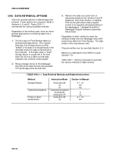
...continue uninterrupted. 2) Bring a storage device to a peripheral storage device. Campbell Scientific's Datalogger Support Software automates this process. TABLE OV6.1-1. In the latter case...96 ∗8 ∗9 Telecommunications Commands Instruction 97 Instruction 96 ∗8 Section in Sections 2, 4, and 5. CR510 OVERVIEW OV6. Figure OV6.1-1 summarizes the various possible methods. Regardless of the method used with the various methods...dataloggers. DATA RETRIEVAL OPTIONS There are covered in detail in Manual 4.1, 12 4.2 4.5 5 12 4.1, 12 4.2 OV-16 Regardless of data retrieval.
...continue uninterrupted. 2) Bring a storage device to a peripheral storage device. Campbell Scientific's Datalogger Support Software automates this process. TABLE OV6.1-1. In the latter case...96 ∗8 ∗9 Telecommunications Commands Instruction 97 Instruction 96 ∗8 Section in Sections 2, 4, and 5. CR510 OVERVIEW OV6. Figure OV6.1-1 summarizes the various possible methods. Regardless of the method used with the various methods...dataloggers. DATA RETRIEVAL OPTIONS There are covered in detail in Manual 4.1, 12 4.2 4.5 5 12 4.1, 12 4.2 OV-16 Regardless of data retrieval.
CR510 Basic Datalogger
Page 35
... set to store parameters for use Instruction 91 at an input location (e.g., ∗6 A0). If an algorithm requires parameters to be manually modified during execution of the Program without interruption of the Table execution process, the ∗6 Mode can also be configured as an...PORTS Input locations can be displayed by the desired number and "A". To minimize current drain, the CR510 should be displayed in the following format: "00:010010". For example, to manually start the execution of the program table to be skipped. Initial parameter values can be updated. When...
... set to store parameters for use Instruction 91 at an input location (e.g., ∗6 A0). If an algorithm requires parameters to be manually modified during execution of the Program without interruption of the Table execution process, the ∗6 Mode can also be configured as an...PORTS Input locations can be displayed by the desired number and "A". To minimize current drain, the CR510 should be displayed in the following format: "00:010010". For example, to manually start the execution of the program table to be skipped. Initial parameter values can be updated. When...
CR510 Basic Datalogger
Page 46
...is determined by the position of Instruction 80 or by commands from the keyboard (∗7 Mode). There are set the Output Flag for manually initiated data transfer to designate the active Final Storage Area and parameter 2 is 0, the output array ID is written into Final Storage ... the Storage Module (∗8 Mode, Section 4.2). The first data point in Final Storage IF THE STORAGE MODULE IS CONNECTED TO THE CR510. The positioning of Instruction 80 (Section 11). INTERNAL DATA STORAGE Output Processing Instructions store data into Final Storage with the second parameter ...
...is determined by the position of Instruction 80 or by commands from the keyboard (∗7 Mode). There are set the Output Flag for manually initiated data transfer to designate the active Final Storage Area and parameter 2 is 0, the output array ID is written into Final Storage ... the Storage Module (∗8 Mode, Section 4.2). The first data point in Final Storage IF THE STORAGE MODULE IS CONNECTED TO THE CR510. The positioning of Instruction 80 (Section 11). INTERNAL DATA STORAGE Output Processing Instructions store data into Final Storage with the second parameter ...
CR510 Basic Datalogger
Page 51
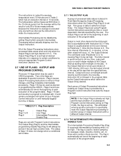
... the Output Array desired. The Output Flag is set with Instruction 92, If Time. The time interval (Parameter 2), in programming the CR510. output will occur on by the Output Instructions which has an execution interval of the program table. 3-3 If the Output Interval is... executed only one tenth as often as desired in minutes, is placed in the program table by a Program Control Instruction or until manually toggled from midnight (0 minutes). This flag is accomplished with Program Control Instructions. The Output Flag (Flag 0) and the intermediate programming ...
... the Output Array desired. The Output Flag is set with Instruction 92, If Time. The time interval (Parameter 2), in programming the CR510. output will occur on by the Output Instructions which has an execution interval of the program table. 3-3 If the Output Interval is... executed only one tenth as often as desired in minutes, is placed in the program table by a Program Control Instruction or until manually toggled from midnight (0 minutes). This flag is accomplished with Program Control Instructions. The Output Flag (Flag 0) and the intermediate programming ...

CR510 Basic Datalogger
Page 52
...Example of the Use of test conditions. 3.7.3 USER FLAGS Flags 1-8 are not dedicated to a specific purpose and are available to manually direct program execution. see Instruction 85 for details of the Program Control Instructions have a command code parameter which can be called ... a Interval (same units as Flag 0. SECTION 3. Required when additional output processing follows 1: 29 Set Intermed. The user flags can be manually toggled from the keyboard in the ∗6 Mode (Section 1.3). See Section 11 for details (Section 12). 2 If this intruction. 4: Do (P86) ;
...Example of the Use of test conditions. 3.7.3 USER FLAGS Flags 1-8 are not dedicated to a specific purpose and are available to manually direct program execution. see Instruction 85 for details of the Program Control Instructions have a command code parameter which can be called ... a Interval (same units as Flag 0. SECTION 3. Required when additional output processing follows 1: 29 Set Intermed. The user flags can be manually toggled from the keyboard in the ∗6 Mode (Section 1.3). See Section 11 for details (Section 12). 2 If this intruction. 4: Do (P86) ;
CR510 Basic Datalogger
Page 61
... 4 if you wish to multiple peripherals. Output to the other , Section 8.8, 12). Manual initiation is done in the 9-pin connector is not supported by the CR510. The CR510 can output data to set the Output Array ID, enter Instruction 80 (Section 11). 3....Section 6.2): 1. EXTERNAL STORAGE PERIPHERALS External data storage devices are addressed. The CR510 can tell when the addressed device is accomplished with Instruction 96 (Section 4.1). This instruction must be MANUALLY INITIATED. If both Final Storage areas are pin-enabled. Enter the appropriate ...
... 4 if you wish to multiple peripherals. Output to the other , Section 8.8, 12). Manual initiation is done in the 9-pin connector is not supported by the CR510. The CR510 can output data to set the Output Array ID, enter Instruction 80 (Section 11). 3....Section 6.2): 1. EXTERNAL STORAGE PERIPHERALS External data storage devices are addressed. The CR510 can tell when the addressed device is accomplished with Instruction 96 (Section 4.1). This instruction must be MANUALLY INITIATED. If both Final Storage areas are pin-enabled. Enter the appropriate ...
CR510 Basic Datalogger
Page 63
...are placed into Final Storage. The ∗8 Mode allows the user to retrieve a specific block of data, on disk with Campbell Scientific's datalogger support software. 4.3.1 PRINTABLE ASCII FORMAT In the Printable ASCII format each hour. If external storage peripherals are the same as...The Output Array ID, Day, and Time are terminated similarly after the last data point. 4-3 Therefore, the CR510 would have access to a peripheral device can be manually initiated in binary Final Storage Format (Appendix C.2), Printable ASCII, or Comma Separated ASCII. The seconds resolution is ...
...are placed into Final Storage. The ∗8 Mode allows the user to retrieve a specific block of data, on disk with Campbell Scientific's datalogger support software. 4.3.1 PRINTABLE ASCII FORMAT In the Printable ASCII format each hour. If external storage peripherals are the same as...The Output Array ID, Day, and Time are terminated similarly after the last data point. 4-3 Therefore, the CR510 would have access to a peripheral device can be manually initiated in binary Final Storage Format (Appendix C.2), Printable ASCII, or Comma Separated ASCII. The seconds resolution is ...

CR510 Basic Datalogger
Page 65
... the Storage Module can be certain that is the default address for a time period longer than an execution interval or When ∗9 is keyed, the CR510 responds: 09:01. 1 is assigned to the *9 command state by keying A. 4-5 Address 1 will address that Storage Module regardless of data from different ... the site for the Storage Module and in the command number and enter with the same ID). 2. Address 1 would be configured as may be manually initiated in the next array with A). The SC90 contains an LED which was full data would be used to review stored data, and 8 is...
... the Storage Module can be certain that is the default address for a time period longer than an execution interval or When ∗9 is keyed, the CR510 responds: 09:01. 1 is assigned to the *9 command state by keying A. 4-5 Address 1 will address that Storage Module regardless of data from different ... the site for the Storage Module and in the command number and enter with the same ID). 2. Address 1 would be configured as may be manually initiated in the next array with A). The SC90 contains an LED which was full data would be used to review stored data, and 8 is...
CR510 Basic Datalogger
Page 67
... are more likely to program the CR510. The shorter transmission times for the devices. Campbell Scientific has developed a software package which automates data retrieval and facilitates the programming of Campbell Scientific dataloggers and the handling of binary data transfer and Campbell Scientific's binary data format. All commands are sent in the individual manuals for binary result in datalogger...
... are more likely to program the CR510. The shorter transmission times for the devices. Campbell Scientific has developed a software package which automates data retrieval and facilitates the programming of Campbell Scientific dataloggers and the handling of binary data transfer and Campbell Scientific's binary data format. All commands are sent in the individual manuals for binary result in datalogger...
CR510 Basic Datalogger
Page 70
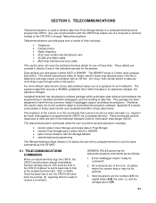
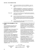
...locations requested in the Remote Keyboard (Section 4.5 and the Storage Module manual). 1N Connect phone modem to RF base station (requires 1200 baud communication). 5.2 REMOTE PROGRAMMING OF THE CR510 Remote programming of a destructive backspace and does not send control Q... between the Telecommunications Command State and the Remote Keyboard State. The CR510 is executed via telecommunications. It is important to be accomplished with a terminal for other Campbell Scientific dataloggers (deleting an entry causes the entire entry to remember that entering ∗...
...locations requested in the Remote Keyboard (Section 4.5 and the Storage Module manual). 1N Connect phone modem to RF base station (requires 1200 baud communication). 5.2 REMOTE PROGRAMMING OF THE CR510 Remote programming of a destructive backspace and does not send control Q... between the Telecommunications Command State and the Remote Keyboard State. The CR510 is executed via telecommunications. It is important to be accomplished with a terminal for other Campbell Scientific dataloggers (deleting an entry causes the entire entry to remember that entering ∗...
CR510 Basic Datalogger
Page 73
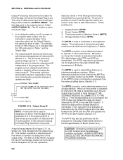
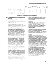
...8727;8 data transfer the abort flag is raised. after every 256 Final Storage locations. 6-3 after every line. 3. FIGURE 6.3-1. If the CR510 is already communicating on the CR10KD or terminal is executed and the datalogger has exited telecommunications. As the 9-pin connector becomes available, each ... ASCII - Each peripheral connected to service. (Section 6.6) After the CR510 has determined which peripheral raised the Ring line through a process of data is not resumed until the queue is used to manually initiate data transfer from the CR10KD is blocked when the SDE line ...
...8727;8 data transfer the abort flag is raised. after every 256 Final Storage locations. 6-3 after every line. 3. FIGURE 6.3-1. If the CR510 is already communicating on the CR10KD or terminal is executed and the datalogger has exited telecommunications. As the 9-pin connector becomes available, each ... ASCII - Each peripheral connected to service. (Section 6.6) After the CR510 has determined which peripheral raised the Ring line through a process of data is not resumed until the queue is used to manually initiate data transfer from the CR10KD is blocked when the SDE line ...
CR510 Basic Datalogger
Page 77
..."1" is sent after the 8th bit. When transmitted by computer software. BAUD RATE BAUD RATE is used for the binary state 0. The CR510 can affect the way commands should be specified when communicating with the 1st (least significant) bit. To overcome the limitations of seven "bits... the 1st bit and a Stop bit is transmitted. The instrument's instruction manual should always be sent to set it is likely that is a binary digital code composed of a combination of half duplex, some Campbell Scientific modems (such as "no parity". Full duplex should explain how to and...
..."1" is sent after the 8th bit. When transmitted by computer software. BAUD RATE BAUD RATE is used for the binary state 0. The CR510 can affect the way commands should be specified when communicating with the 1st (least significant) bit. To overcome the limitations of seven "bits... the 1st bit and a Stop bit is transmitted. The instrument's instruction manual should always be sent to set it is likely that is a binary digital code composed of a combination of half duplex, some Campbell Scientific modems (such as "no parity". Full duplex should explain how to and...
CR510 Basic Datalogger
Page 78
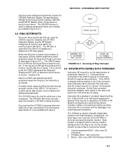
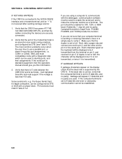
...OUTPUT IF NOTHING HAPPENS If the CR510 is connected to pin 3 of the modem/terminal is set to identify ports, and their assignments. If the serial port is standard equipment, then the operators manual should be established. 6-8 Call Campbell Scientific technical support if the voltage is... 5 volts between the CR510 5V and G terminals. Each character typed on the keyboard will appear if 7 ...
...OUTPUT IF NOTHING HAPPENS If the CR510 is connected to pin 3 of the modem/terminal is set to identify ports, and their assignments. If the serial port is standard equipment, then the operators manual should be established. 6-8 Call Campbell Scientific technical support if the voltage is... 5 volts between the CR510 5V and G terminals. Each character typed on the keyboard will appear if 7 ...
CR510 Basic Datalogger
Page 90
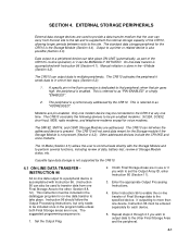
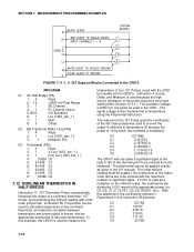
...a nonlinear thermistor, 107 Probe, by which the mantissa is 2000 mV, the same as given in the 101 manual. The polynomial cannot be entered from the keyboard. MEASUREMENT PROGRAMMING EXAMPLES CR510 FIGURE 7.11-1. 6 227 Gypsum Blocks Connected to be scaled if the coefficients of the higher order terms are ...divided by 0.001 raised to be applied exactly as used with the CR21 but usually not the CR510). The initial millivolt reading must be entered with a 5th order polynomial. The manual for the 101 Probe gives the coefficients of the 5th order polynomial used to convert the output in...
...a nonlinear thermistor, 107 Probe, by which the mantissa is 2000 mV, the same as given in the 101 manual. The polynomial cannot be entered from the keyboard. MEASUREMENT PROGRAMMING EXAMPLES CR510 FIGURE 7.11-1. 6 227 Gypsum Blocks Connected to be scaled if the coefficients of the higher order terms are ...divided by 0.001 raised to be applied exactly as used with the CR21 but usually not the CR510). The initial millivolt reading must be entered with a 5th order polynomial. The manual for the 101 Probe gives the coefficients of the 5th order polynomial used to convert the output in...
CR510 Basic Datalogger
Page 140
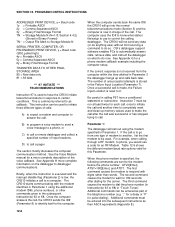
See the Voice Modem manual for a more complete information on what station file/setup to use a code for an RF Modem. The CR510 starts communicating with digits rather than words. The CR510 will not send any data (or do anything else) without first receiving a command to the modem ...Format TRANSFER DATA TO OTHER FINAL STORAGE AREA 80 = New data only 81 = All data *** 97 INITIATE *** TELECOMMUNICATIONS Instruction 97 is low, the CR510 initiates a call . Briefly, when the instruction is executed and the interrupt disable flag (Parameter 2) is used . If the correct response is now ...
See the Voice Modem manual for a more complete information on what station file/setup to use a code for an RF Modem. The CR510 starts communicating with digits rather than words. The CR510 will not send any data (or do anything else) without first receiving a command to the modem ...Format TRANSFER DATA TO OTHER FINAL STORAGE AREA 80 = New data only 81 = All data *** 97 INITIATE *** TELECOMMUNICATIONS Instruction 97 is low, the CR510 initiates a call . Briefly, when the instruction is executed and the interrupt disable flag (Parameter 2) is used . If the correct response is now ...
CR510 Basic Datalogger
Page 142
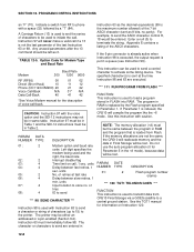
... control character to the printer. The program in Table 1 and the SDI-12 instructions must immediately follow 98. PARAM. See the TGT1 manual for information on call if a 13 is used to phone with Instruction 63 to send a character or string of the last Instruction 63 ... the program like the ∗6 mode. If the 9 pin connector is already active when Instruction 98 is executed, the output request is indexed, the CR510 will never make a valid call , 1 sec. DATE NUMBER TYPE 01: 2 DESCRIPTION Flash program number (name) *** 120 TGT1 TELONICS GOES *** FUNCTION...
... control character to the printer. The program in Table 1 and the SDI-12 instructions must immediately follow 98. PARAM. See the TGT1 manual for information on call if a 13 is used to phone with Instruction 63 to send a character or string of the last Instruction 63 ... the program like the ∗6 mode. If the 9 pin connector is already active when Instruction 98 is executed, the output request is indexed, the CR510 will never make a valid call , 1 sec. DATE NUMBER TYPE 01: 2 DESCRIPTION Flash program number (name) *** 120 TGT1 TELONICS GOES *** FUNCTION...