MD485 RS-485 Multidrop Interface
Page 2
... the problem, an RMA number will be issued. This warranty shall not apply to Campbell Scientific, Inc. directly. To obtain a Returned Materials Authorization (RMA), contact Campbell Scientific, Inc., phone (435) 753-2342. to repairing or replacing (at www.campbellsci.com/repair. Batteries have been subjected to 435-750-9579. Campbell Scientific, Inc.'s obligation under normal use and service for a particular purpose. Campbell Scientific, Inc. The following contact information is : CAMPBELL SCIENTIFIC...
... the problem, an RMA number will be issued. This warranty shall not apply to Campbell Scientific, Inc. directly. To obtain a Returned Materials Authorization (RMA), contact Campbell Scientific, Inc., phone (435) 753-2342. to repairing or replacing (at www.campbellsci.com/repair. Batteries have been subjected to 435-750-9579. Campbell Scientific, Inc.'s obligation under normal use and service for a particular purpose. Campbell Scientific, Inc. The following contact information is : CAMPBELL SCIENTIFIC...
MD485 RS-485 Multidrop Interface
Page 7
..., 57.6K, 38.4K, 19.2K, 9600, 1200 Communication cable: CABLE2TP-L two-twisted-pair cable 1 Specifications Size: 6.25 x 2.5 x .75 in the system is configurable to an RS-485 network (using Campbell Scientific's LoggerNet or similar software, the operation of the MD485 in . (15.88 x 6.35 x 1.91 cm) Weight: 4.5 oz. (127.6 g) Accessories: RS-232 cable, SC12 cable, 3-pin Terminal Block (2) Voltage: 12 Volts from datalogger or Transformer...
..., 57.6K, 38.4K, 19.2K, 9600, 1200 Communication cable: CABLE2TP-L two-twisted-pair cable 1 Specifications Size: 6.25 x 2.5 x .75 in the system is configurable to an RS-485 network (using Campbell Scientific's LoggerNet or similar software, the operation of the MD485 in . (15.88 x 6.35 x 1.91 cm) Weight: 4.5 oz. (127.6 g) Accessories: RS-232 cable, SC12 cable, 3-pin Terminal Block (2) Voltage: 12 Volts from datalogger or Transformer...

MD485 RS-485 Multidrop Interface
Page 8
... RS-485 receiving error. This most likely indicates a wiring problem between the CS I/O connector and the RS-232 connector (A) indicates activity on the CS I/O port, and the other active port (CS I/O or RS-232). When CS I/O and RS-232 are the active ports, the LED between the RS-485 ports of the base and remote MD485s. The LEDs then begin flashing once every...
... RS-485 receiving error. This most likely indicates a wiring problem between the CS I/O connector and the RS-232 connector (A) indicates activity on the CS I/O port, and the other active port (CS I/O or RS-232). When CS I/O and RS-232 are the active ports, the LED between the RS-485 ports of the base and remote MD485s. The LEDs then begin flashing once every...

MD485 RS-485 Multidrop Interface
Page 9
... I/O port while setting MD485 parameters on the MD485. MD485 Setup using the Device Configuration (DevConfig) utility, which is typically configured using DevConfig 3 Using DevConfig, you exit the Setup Menu. Changed settings are saved in Flash memory. MD485 RS-485 Multidrop Interface 3.1.3 Configuring the MD485 The MD485 is included with the message "Setup Timeout." Alternatively, a Setup Menu can be downloaded at no charge from our web site. If left idle, the Setup Menu will time...
... I/O port while setting MD485 parameters on the MD485. MD485 Setup using the Device Configuration (DevConfig) utility, which is typically configured using DevConfig 3 Using DevConfig, you exit the Setup Menu. Changed settings are saved in Flash memory. MD485 RS-485 Multidrop Interface 3.1.3 Configuring the MD485 The MD485 is included with the message "Setup Timeout." Alternatively, a Setup Menu can be downloaded at no charge from our web site. If left idle, the Setup Menu will time...
MD485 RS-485 Multidrop Interface
Page 10
...) of reverse polarity power. 3.3 RS-485 Cable The connection between supply inputs). MD485 RS-485 Multidrop Interface NOTE The baud rate for each port is set on other twisted pair is used for the differential data ("A" connects to "A"; Regardless of all MD485s in this manual.) The typical remote MD485 will be set to the same baud rate. 3.2 Power Supplies The typical base station MD485 connected directly to a PC uses a wall transformer to supply 12 VDC power.
...) of reverse polarity power. 3.3 RS-485 Cable The connection between supply inputs). MD485 RS-485 Multidrop Interface NOTE The baud rate for each port is set on other twisted pair is used for the differential data ("A" connects to "A"; Regardless of all MD485s in this manual.) The typical remote MD485 will be set to the same baud rate. 3.2 Power Supplies The typical base station MD485 connected directly to a PC uses a wall transformer to supply 12 VDC power.
MD485 RS-485 Multidrop Interface
Page 11
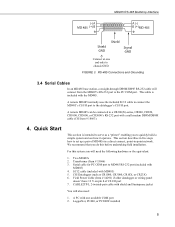
... Connections and Grounding 3.4 Serial Cables In an MD485 base station, a straight-through DB9M/DB9F RS-232 cable will also need the following hardware or the equivalent: 1. CABLE2TP-L 2-twisted-pair cable with MD485) 5. A remote MD485 can be connected to the PC COM port. LoggerNet, PC400, or PC208W installed 5 FIGURE 3. Transformer (Item # 15966) 3. This cable is intended to set up a pair of CS I /O port. Field Power Cable (Item # 14291) if older datalogger or wiring...
... Connections and Grounding 3.4 Serial Cables In an MD485 base station, a straight-through DB9M/DB9F RS-232 cable will also need the following hardware or the equivalent: 1. CABLE2TP-L 2-twisted-pair cable with MD485) 5. A remote MD485 can be connected to the PC COM port. LoggerNet, PC400, or PC208W installed 5 FIGURE 3. Transformer (Item # 15966) 3. This cable is intended to set up a pair of CS I /O port. Field Power Cable (Item # 14291) if older datalogger or wiring...

MD485 RS-485 Multidrop Interface
Page 12
... CR10 Wiring Panels PS512M Power Supply SERIAL NUMBER < 1765 < 2779 < 13443 All (black, gray, silver) < 1712 When you connect power to the MD485 (through the SC12 cable or the optional Field Power Cable) you can be left in Step 1 (assuming datalogger is powered). 6 TABLE 2. Plug transformer into AC outlet and plug barrel connector into base MD485 "DC Pwr" jack. Using DevConfig or the MD485 setup menu as explained in Section 3.1.3, change the active ports...
... CR10 Wiring Panels PS512M Power Supply SERIAL NUMBER < 1765 < 2779 < 13443 All (black, gray, silver) < 1712 When you connect power to the MD485 (through the SC12 cable or the optional Field Power Cable) you can be left in Step 1 (assuming datalogger is powered). 6 TABLE 2. Plug transformer into AC outlet and plug barrel connector into base MD485 "DC Pwr" jack. Using DevConfig or the MD485 setup menu as explained in Section 3.1.3, change the active ports...
MD485 RS-485 Multidrop Interface
Page 13
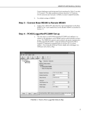
... not listed, check for 12 V between CS I/O connector pin 8 and pin 2 (GND) or contact Campbell Scientific. Connect Base MD485 to -Point LoggerNet Network Map 7 Connect the CABLE2TP cable from the 3-pin terminal block on the Base MD485 to PC400/LoggerNet/PC208W. The MD485 in the Device Map. Use default settings of MD485. If not using the EZSetup Wizard, simply add a datalogger to a COM port in a point-to-point network can operate transparent...
... not listed, check for 12 V between CS I/O connector pin 8 and pin 2 (GND) or contact Campbell Scientific. Connect Base MD485 to -Point LoggerNet Network Map 7 Connect the CABLE2TP cable from the 3-pin terminal block on the Base MD485 to PC400/LoggerNet/PC208W. The MD485 in the Device Map. Use default settings of MD485. If not using the EZSetup Wizard, simply add a datalogger to a COM port in a point-to-point network can operate transparent...

MD485 RS-485 Multidrop Interface
Page 14
... CS I/O FIGURE 6. Datalogger program transfer and data collection are now ready to Connect to your datalogger using MD485s. The datalogger "Extra Response Time" can be left at which is the rate at 0. Step 5 - System Configuration The block diagram in Figure 6 depicts the connection of a computer to -Multipoint Network 8 MD485 Point-to a network of Campbell Scientific dataloggers using PC400, LoggerNet, or PC208W Connect screen. Set the Maximum Baud...
... CS I/O FIGURE 6. Datalogger program transfer and data collection are now ready to Connect to your datalogger using MD485s. The datalogger "Extra Response Time" can be left at which is the rate at 0. Step 5 - System Configuration The block diagram in Figure 6 depicts the connection of a computer to -Multipoint Network 8 MD485 Point-to a network of Campbell Scientific dataloggers using PC400, LoggerNet, or PC208W Connect screen. Set the Maximum Baud...

MD485 RS-485 Multidrop Interface
Page 15
... I /O port. When data needs to be represented in the MD485 Setup Menu. When using the CS I /O configurations. Figure 7 shows an MD485 being used as a transparent device, the MD485 simply passes serial data from the datalogger CS I /O interface converter. A transformer supplies +12 VDC power to another. If communication rates are chosen as a full-duplex device, fully compatible with the CABLE2TP cable. In this mode the MD485 uses what is powered from...
... I /O port. When data needs to be represented in the MD485 Setup Menu. When using the CS I /O configurations. Figure 7 shows an MD485 being used as a transparent device, the MD485 simply passes serial data from the datalogger CS I /O interface converter. A transformer supplies +12 VDC power to another. If communication rates are chosen as a full-duplex device, fully compatible with the CABLE2TP cable. In this mode the MD485 uses what is powered from...

MD485 RS-485 Multidrop Interface
Page 18
... null modem cable to MD485 to MD485 to datalogger (see Appendix D) 5) Network to MD485: PC to Internet to NL100 to MD485 to MD485s then through null modem cable (or PS100 with PakBus addresses. They must be extended (see Appendix F). When using the MD9 emulation, PC400 software does not support these combined communication options; Networks with the CC640 digital camera and the AVW200 Vibrating Wire Interface...
... null modem cable to MD485 to MD485 to datalogger (see Appendix D) 5) Network to MD485: PC to Internet to NL100 to MD485 to MD485s then through null modem cable (or PS100 with PakBus addresses. They must be extended (see Appendix F). When using the MD9 emulation, PC400 software does not support these combined communication options; Networks with the CC640 digital camera and the AVW200 Vibrating Wire Interface...
MD485 RS-485 Multidrop Interface
Page 19
...-safe circuitry, which is possible through MD485s in transparent mode. Wiring Specifications 8.1 RS-485 Line Length The EIA/TIA RS-485 communications standard, an upgrade of RS-422, supports 32 devices (driver/receiver pairs) in a party line or multi-drop mode, on the bus. It does not specify cable type or data rate. The MD485 has a 1/8-unit-load receiver input impedance (96k ohm) that minimize EMI...
...-safe circuitry, which is possible through MD485s in transparent mode. Wiring Specifications 8.1 RS-485 Line Length The EIA/TIA RS-485 communications standard, an upgrade of RS-422, supports 32 devices (driver/receiver pairs) in a party line or multi-drop mode, on the bus. It does not specify cable type or data rate. The MD485 has a 1/8-unit-load receiver input impedance (96k ohm) that minimize EMI...
MD485 RS-485 Multidrop Interface
Page 20
... the ground wire. This connection should be no more information on ground connections. 8.3 Protection and Isolation The MD485 incorporates gas tubes and multilayer varistors on the distant node. It rarely solves problems when used as possible. • Connect the "signal ground" wire between MD485s. • Ground the shield at every node. The Model 485OP can also be used in the kilobit data range. In most...
... the ground wire. This connection should be no more information on ground connections. 8.3 Protection and Isolation The MD485 incorporates gas tubes and multilayer varistors on the distant node. It rarely solves problems when used as possible. • Connect the "signal ground" wire between MD485s. • Ground the shield at every node. The Model 485OP can also be used in the kilobit data range. In most...

MD485 RS-485 Multidrop Interface
Page 23
...) BATTERY - The SC12 cable from the COM220 is not possible with an MD485. A Campbell Scientific Model COM220 Telephone Modem is used in place of the PS100/A100 for system operation and the A100 performs the function of a null modem (the COM220 and MD485 are both "modem" devices). Connection to communicate with PakBus Networking. POWER TO 12V TERMINALS CHARGE CHARGE +12V FROM CHARGER OR...
...) BATTERY - The SC12 cable from the COM220 is not possible with an MD485. A Campbell Scientific Model COM220 Telephone Modem is used in place of the PS100/A100 for system operation and the A100 performs the function of a null modem (the COM220 and MD485 are both "modem" devices). Connection to communicate with PakBus Networking. POWER TO 12V TERMINALS CHARGE CHARGE +12V FROM CHARGER OR...
MD485 RS-485 Multidrop Interface
Page 29
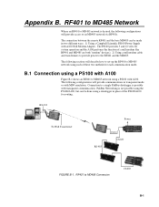
... in transparent mode or with A100 Null Modem Adapter. B.1 Connection using a PS100 with A100 Figure B-1 shows an RF401 to an MD485 network via RF401s. The following configurations will describe how to set-up the RF401 to the RF401 and the MD485. The following sections will provide communications in two different ways. 1) Using a Campbell Scientific PS100 Power Supply with MD9 emulation. EXTERNAL RECHARGEABLE BATTERY Logan, Utah...
... in transparent mode or with A100 Null Modem Adapter. B.1 Connection using a PS100 with A100 Figure B-1 shows an RF401 to an MD485 network via RF401s. The following configurations will describe how to set-up the RF401 to the RF401 and the MD485. The following sections will provide communications in two different ways. 1) Using a Campbell Scientific PS100 Power Supply with MD9 emulation. EXTERNAL RECHARGEABLE BATTERY Logan, Utah...
MD485 RS-485 Multidrop Interface
Page 32
... PS100. When you turn on the PS100 supply, the MD485 receives 12V power and you are ready to connect to set up hardware. Remote MD485s normally connect to the CS I /O and RS-485" 2) Communication Mode - The following configurations will see the LEDs light in their power-up the datalogger will start the MD485 operating. Three transformers (CSI Item #15966) d. Desired baud rate b. Remote MD485s 1) Active Ports - "MD9 Emulation" with...
... PS100. When you turn on the PS100 supply, the MD485 receives 12V power and you are ready to connect to set up hardware. Remote MD485s normally connect to the CS I /O and RS-485" 2) Communication Mode - The following configurations will see the LEDs light in their power-up the datalogger will start the MD485 operating. Three transformers (CSI Item #15966) d. Desired baud rate b. Remote MD485s 1) Active Ports - "MD9 Emulation" with...

MD485 RS-485 Multidrop Interface
Page 37
.... INTERNAL (12V 7 AMP HOUR) BATTERY - MD485 to RF401 network is desired, the following sections will provide communications in two different ways. 1) Using a Campbell Scientific PS100 Power Supply with transparent communication. The following configurations will describe how to set-up the MD485 to RF401 network using a datalogger in place of the PS100/A100 for each communication mode. The connection between the remote MD485 and the base RF401...
.... INTERNAL (12V 7 AMP HOUR) BATTERY - MD485 to RF401 network is desired, the following sections will provide communications in two different ways. 1) Using a Campbell Scientific PS100 Power Supply with transparent communication. The following configurations will describe how to set-up the MD485 to RF401 network using a datalogger in place of the PS100/A100 for each communication mode. The connection between the remote MD485 and the base RF401...

MD485 RS-485 Multidrop Interface
Page 48
... DC Pwr jack of the digital cellular modem and the base MD485. SC12 cables (one included with MD9 Emulation or PakBus Networking. 1. Dataloggers - Remote MD485 1) Active Ports - Attach the null modem cable to the datalogger. HARDWARE REQUIREMENTS a. MD485s b. CABLE2TP cable D-4 c. corresponding PakBus address, other setting defaults, schedule collections as desired MD485 Configuration a. "RS-232 and RS-485" 2) Communication Mode - "PakBus Networking" 3) RS-232 Port Configuration - Powering up hardware...
... DC Pwr jack of the digital cellular modem and the base MD485. SC12 cables (one included with MD9 Emulation or PakBus Networking. 1. Dataloggers - Remote MD485 1) Active Ports - Attach the null modem cable to the datalogger. HARDWARE REQUIREMENTS a. MD485s b. CABLE2TP cable D-4 c. corresponding PakBus address, other setting defaults, schedule collections as desired MD485 Configuration a. "RS-232 and RS-485" 2) Communication Mode - "PakBus Networking" 3) RS-232 Port Configuration - Powering up hardware...

MD485 RS-485 Multidrop Interface
Page 61
... CABLE5CBL cable to MD485 Connection Hardware Requirements a. Camera to the terminal block on the MD485. Communication Mode - a. RS-485 b. F-1 SC12 cable (one included with shield and Santoprene jacket MD485 Configuration a. Active Ports - SDC7 or SDC8 d. PakBus Networking c. MD485 b. CC640 Digital Camera c. PakBus Address -set to CC640 Digital Camera The MD485 is used with PakBus networking. MD485 to a unique value in the PakBus network c. MD485 to CC640 communications is only supported with the CC640 Digital Camera...
... CABLE5CBL cable to MD485 Connection Hardware Requirements a. Camera to the terminal block on the MD485. Communication Mode - a. RS-485 b. F-1 SC12 cable (one included with shield and Santoprene jacket MD485 Configuration a. Active Ports - SDC7 or SDC8 d. PakBus Networking c. MD485 b. CC640 Digital Camera c. PakBus Address -set to CC640 Digital Camera The MD485 is used with PakBus networking. MD485 to a unique value in the PakBus network c. MD485 to CC640 communications is only supported with the CC640 Digital Camera...

MD485 RS-485 Multidrop Interface
Page 65
... 12 VDC to power peripherals Serial data transmit line I /O port is Campbell Scientific's input/output port. It is configured as Data Communications Equipment (DCE) for direct cable connection to Data Terminal Equipment (DTE) such as a printer enable Used by datalogger to a datalogger. It is a partial implementation of RS-232C. MD485 Port Pin Descriptions CS I/O Port The CS I = Signal Into the MD485, O = Signal Out of the MD485, NC = No Connection RS-232 Port The "RS-232...
... 12 VDC to power peripherals Serial data transmit line I /O port is Campbell Scientific's input/output port. It is configured as Data Communications Equipment (DCE) for direct cable connection to Data Terminal Equipment (DTE) such as a printer enable Used by datalogger to a datalogger. It is a partial implementation of RS-232C. MD485 Port Pin Descriptions CS I/O Port The CS I = Signal Into the MD485, O = Signal Out of the MD485, NC = No Connection RS-232 Port The "RS-232...
