
Service Manual
Page 4
... produced with local law. When amendments are the registered trademarks or trademarks of Canon Inc. except in part, without the express written consent of the individual companies. BJ Products Quality Support Dept. 16-1, Shimonoge 3-chome, Takatsu-ku, Kawasaki-shi, Kanagawa 213, Japan... NTX-J laser beam printer; The following paragraph does not apply to the content of this manual, Canon will publish a revised version of internal business use. CANON INC. Copyright This manual is published by Canon Inc. Copyright © 1999 by Canon Inc. A Canon mo-5001S Magneto-Optical...
... produced with local law. When amendments are the registered trademarks or trademarks of Canon Inc. except in part, without the express written consent of the individual companies. BJ Products Quality Support Dept. 16-1, Shimonoge 3-chome, Takatsu-ku, Kawasaki-shi, Kanagawa 213, Japan... NTX-J laser beam printer; The following paragraph does not apply to the content of this manual, Canon will publish a revised version of internal business use. CANON INC. Copyright This manual is published by Canon Inc. Copyright © 1999 by Canon Inc. A Canon mo-5001S Magneto-Optical...

Service Manual
Page 8
... 1 5- 1 5- 1 5- 2 5- 2 5- 3 5- 4 5- 4 5- 4 5- 4 5- 5 5- 6 5- 6 5- 7 5- 8 5- 8 3.1.3 Purge unit 3.1.4 Paper feed unit 3.2 BJ Cartridge 3.2.1 Construction of the Black BJ cartridge 3.2.2 Construction of the Color/Photo BJ cartridge 3.2.3 Construction of the bubble jet head unit 3.3 Purge Unit 3.3.1 Function of the purge unit 3.3.2 Construction of the purge unit 3.4 Paper Feed Unit... Reassembly 4.2.1 Unlocking the carriage 4.2.2 Removing the printer unit 4.2.3 Removing the ASF unit 4.2.4 Removing the adjustable bearings supporting the carriage shaft 4.2.5 Paper feed gears 5. APPLYING GREASE 4.
... 1 5- 1 5- 1 5- 2 5- 2 5- 3 5- 4 5- 4 5- 4 5- 4 5- 5 5- 6 5- 6 5- 7 5- 8 5- 8 3.1.3 Purge unit 3.1.4 Paper feed unit 3.2 BJ Cartridge 3.2.1 Construction of the Black BJ cartridge 3.2.2 Construction of the Color/Photo BJ cartridge 3.2.3 Construction of the bubble jet head unit 3.3 Purge Unit 3.3.1 Function of the purge unit 3.3.2 Construction of the purge unit 3.4 Paper Feed Unit... Reassembly 4.2.1 Unlocking the carriage 4.2.2 Removing the printer unit 4.2.3 Removing the ASF unit 4.2.4 Removing the adjustable bearings supporting the carriage shaft 4.2.5 Paper feed gears 5. APPLYING GREASE 4.

Service Manual
Page 11
...) Interface Timing (Nibble Mode) Interface Timing (ECP mode, reverse transfer) Automatic Printing Position Alignment Printer's Mechanical System Black BJ Cartridge Color/Photo BJ Cartridge Bubble Jet Nozzle (part) Nozzle Arrangement Signal Contacts Purge Unit Purge Unit Pumping ... Sensor Part 5: MAINTENANCE Figure 5- 1 Grease Points Figure 5- 2 Unlocking the Carriage Figure 5- 3 Removing the Printer Unit Figure 5- 4 Removing the ASF Unit Figure 5- 5 Adjustable Bearings Supporting the Carriage Shaft Figure 5- 6 Feed Gear Unit Precautions Figure 5- 7 Carriage Belt Tension Adjustment Figure 5- 8 ...
...) Interface Timing (Nibble Mode) Interface Timing (ECP mode, reverse transfer) Automatic Printing Position Alignment Printer's Mechanical System Black BJ Cartridge Color/Photo BJ Cartridge Bubble Jet Nozzle (part) Nozzle Arrangement Signal Contacts Purge Unit Purge Unit Pumping ... Sensor Part 5: MAINTENANCE Figure 5- 1 Grease Points Figure 5- 2 Unlocking the Carriage Figure 5- 3 Removing the Printer Unit Figure 5- 4 Removing the ASF Unit Figure 5- 5 Adjustable Bearings Supporting the Carriage Shaft Figure 5- 6 Feed Gear Unit Precautions Figure 5- 7 Carriage Belt Tension Adjustment Figure 5- 8 ...

Service Manual
Page 31
BJC-6000 Part 2: Product Specifications 1. It accommodates two "drop-modulation" BJ cartridges on its carriage. For high quality use . The BJ cartridges use ink tanks which can be replaced individually, and whose quality is a desktop business/personal color bubble-jet printer for quality equal to lower running cost. For high speed use, a pigment-Black BJ...
BJC-6000 Part 2: Product Specifications 1. It accommodates two "drop-modulation" BJ cartridges on its carriage. For high quality use . The BJ cartridges use ink tanks which can be replaced individually, and whose quality is a desktop business/personal color bubble-jet printer for quality equal to lower running cost. For high speed use, a pigment-Black BJ...

Service Manual
Page 32
...BJC-6000 1.2 Features · Laser-printer quality using pigment black ink · Dual-cartridge system High quality printing at high speed from a combination of the Black and Color cartridges or the Color and Photo cartridges Black BJ cartridge: Drop modulation, replaceable ink tank (pigment black), 160 nozzle head Color...183; Automatic printing position adjustment Ensures accurate printing position regardless of cartridges being used or carriage movement direction · Supports a wide variety of print media · Up to A4/Letter full-bleed size paper and banner paper can be used &#...
...BJC-6000 1.2 Features · Laser-printer quality using pigment black ink · Dual-cartridge system High quality printing at high speed from a combination of the Black and Color cartridges or the Color and Photo cartridges Black BJ cartridge: Drop modulation, replaceable ink tank (pigment black), 160 nozzle head Color...183; Automatic printing position adjustment Ensures accurate printing position regardless of cartridges being used or carriage movement direction · Supports a wide variety of print media · Up to A4/Letter full-bleed size paper and banner paper can be used &#...
Service Manual
Page 40
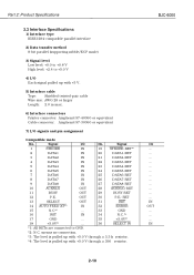
... BUSY OUT 29 BUSY-RET 12 P.E. Signal I /O IN OUT IN 2-10 BJC-6000 I /O No. Part 2: Product Specifications 2.3 Interface Specifications 1) Interface type IEEE1284-compatible parallel interface 2) Data transfer method 8-bit parallel (supporting nibble/ECP mode) 3) Signal level Low level: +0.0 to +0.8 V High level... Type: Shielded twisted-pair cable Wire size: AWG 28 or larger Length: 2.0 m max. 6) Interface connectors Printer connector: Amphenol 57-40360 or equivalent Cable connector: Amphenol 57-30360 or equivalent 7) I/O signals and pin assignment Compatible mode No.
... BUSY OUT 29 BUSY-RET 12 P.E. Signal I /O IN OUT IN 2-10 BJC-6000 I /O No. Part 2: Product Specifications 2.3 Interface Specifications 1) Interface type IEEE1284-compatible parallel interface 2) Data transfer method 8-bit parallel (supporting nibble/ECP mode) 3) Signal level Low level: +0.0 to +0.8 V High level... Type: Shielded twisted-pair cable Wire size: AWG 28 or larger Length: 2.0 m max. 6) Interface connectors Printer connector: Amphenol 57-40360 or equivalent Cable connector: Amphenol 57-30360 or equivalent 7) I/O signals and pin assignment Compatible mode No.

Service Manual
Page 43
... the pulse width of Host Clk. INIT (Input) When this signal goes "L," the printer is disabled. During negotiation, this signal tells the host computer whether or not the printer supports the nibble mode. This signal is the trigger signal for reading Data 1-8. When the ... the printer's mode settings (whether nibble mode is supported, reverse transmission data is a STROBE signal for sending the protocol confirmation to be maintained for notifying the host computer of the data by making Host Busy "H." Data 1-8 (Input) The printer receives data in response. BJC-6000 Part ...
... the pulse width of Host Clk. INIT (Input) When this signal goes "L," the printer is disabled. During negotiation, this signal tells the host computer whether or not the printer supports the nibble mode. This signal is the trigger signal for reading Data 1-8. When the ... the printer's mode settings (whether nibble mode is supported, reverse transmission data is a STROBE signal for sending the protocol confirmation to be maintained for notifying the host computer of the data by making Host Busy "H." Data 1-8 (Input) The printer receives data in response. BJC-6000 Part ...

Service Manual
Page 58
... to power on or off . Operator Panel Indicator Not lit when powered off the printer. BJC-6000 Paper Guide Lightly press this button to align them into the printer one by one. Set it to make the printer ready. When lit in orange, an error has occurred, and the print cannot print... Connects to support larger size paper. Part 3: Operating Instructions 1.4 Names of Parts and Their Functions The main parts of Parts and Their Functions 3-10 Auto Sheet Feeder Set sheets of the carriage holds the Black or Photo BJ cartridge, and the right side holds the Color BJ cartridge....
... to power on or off . Operator Panel Indicator Not lit when powered off the printer. BJC-6000 Paper Guide Lightly press this button to align them into the printer one by one. Set it to make the printer ready. When lit in orange, an error has occurred, and the print cannot print... Connects to support larger size paper. Part 3: Operating Instructions 1.4 Names of Parts and Their Functions The main parts of Parts and Their Functions 3-10 Auto Sheet Feeder Set sheets of the carriage holds the Black or Photo BJ cartridge, and the right side holds the Color BJ cartridge....
Service Manual
Page 82
... DRAM, it generates the ACNKLG signal and turns BUSY "Low" to the host computer the status data, including the device ID, printer status, etc. Part 4: Technical Reference BJC-6000 2. FIRMWARE 2.1 Interface This printer's interface supports compatible mode, nibble mode, and ECP mode in 8 bit units. It should be noted, however, that the computer must be...
... DRAM, it generates the ACNKLG signal and turns BUSY "Low" to the host computer the status data, including the device ID, printer status, etc. Part 4: Technical Reference BJC-6000 2. FIRMWARE 2.1 Interface This printer's interface supports compatible mode, nibble mode, and ECP mode in 8 bit units. It should be noted, however, that the computer must be...
Service Manual
Page 101
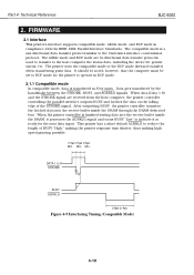
... Paper Thickness Selector Lever Eccentric Bearing Carriage Shaft Plain Paper Position Thick Paper Position Figure 4-23 Paper Thickness Adjustment Mechanism 4-29 This printer is supported by means of an eccentric bearing. BJC-6000 Part 4: Technical Reference b) Paper thickness adjustment The clearance between the head face of the BJ cartridge and the paper varies with...
... Paper Thickness Selector Lever Eccentric Bearing Carriage Shaft Plain Paper Position Thick Paper Position Figure 4-23 Paper Thickness Adjustment Mechanism 4-29 This printer is supported by means of an eccentric bearing. BJC-6000 Part 4: Technical Reference b) Paper thickness adjustment The clearance between the head face of the BJ cartridge and the paper varies with...
Service Manual
Page 107
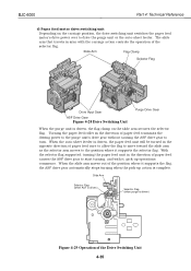
...paper feed transmits the driving power to the purge unit's drive gear without causing the ASF drive gear to the position where it supports the selector flag. Slide Arm Flag Clamp Selector Flag Drive Input Gear ASF Drive Gear Figure 4-28 Drive Switching Unit Purge Drive Gear...arm as the selector arm moves to turn. With the selector flag supported, turning the paper feed unit in sync with it supports the flag, the ASF drive gear automatically stops turning when the pick-up operations commence. BJC-6000 Part 4: Technical Reference d) Paper feed motor drive switching unit Depending...
...paper feed transmits the driving power to the purge unit's drive gear without causing the ASF drive gear to the position where it supports the selector flag. Slide Arm Flag Clamp Selector Flag Drive Input Gear ASF Drive Gear Figure 4-28 Drive Switching Unit Purge Drive Gear...arm as the selector arm moves to turn. With the selector flag supported, turning the paper feed unit in sync with it supports the flag, the ASF drive gear automatically stops turning when the pick-up operations commence. BJC-6000 Part 4: Technical Reference d) Paper feed motor drive switching unit Depending...
Service Manual
Page 124
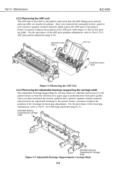
...up roller are adjusted and secured to the printer frame so that of the pickup roller. For the procedure of the head gap adjustment, refer to Part 5: 5.2.4 Head gap adjustment (page 5-11). Part 5: Maintenance BJC-6000 4.2.3 Removing the ASF unit The ASF unit... is maintained for head gap adjustment. Assembly Screw (Red) ASF Unit Assembly Screws (Red) Figure 5-4 Removing the ASF Unit 4.2.4 Removing the adjustable bearings supporting the carriage shaft The adjustable bearings supporting the carriage shaft are ...
...up roller are adjusted and secured to the printer frame so that of the pickup roller. For the procedure of the head gap adjustment, refer to Part 5: 5.2.4 Head gap adjustment (page 5-11). Part 5: Maintenance BJC-6000 4.2.3 Removing the ASF unit The ASF unit... is maintained for head gap adjustment. Assembly Screw (Red) ASF Unit Assembly Screws (Red) Figure 5-4 Removing the ASF Unit 4.2.4 Removing the adjustable bearings supporting the carriage shaft The adjustable bearings supporting the carriage shaft are ...
Service Manual
Page 126
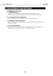
Part 5: Maintenance BJC-6000 5. ADJUSTMENTS AND SETTINGS 5.1 Adjustments and Settings 5.1.1 EEPROM setting 1) When the control board is replaced (see Figure 4 of the parts catalog). 2) When the waste ink absorber ... screws painted red are loosened)(see Figure 10 of the parts catalog). 5.1.4 Head gap adjustment When the screws securing the adjustable bearings (painted red) that support the carriage shaft are loosened (see Figure 12 of the parts catalog). 5-8
Part 5: Maintenance BJC-6000 5. ADJUSTMENTS AND SETTINGS 5.1 Adjustments and Settings 5.1.1 EEPROM setting 1) When the control board is replaced (see Figure 4 of the parts catalog). 2) When the waste ink absorber ... screws painted red are loosened)(see Figure 10 of the parts catalog). 5.1.4 Head gap adjustment When the screws securing the adjustable bearings (painted red) that support the carriage shaft are loosened (see Figure 12 of the parts catalog). 5-8

Service Manual
Page 129
...gauge is clean and not deformed. Ensure that CAUTION the platen is to be put on next. 2) Raise both the right and left adjustable bearings supporting the carriage shaft in the direction of arrow 1, and temporarily fix the bearings in that position using the fixing screws (red). 3) Remove the right...(red) Fixing Screw (painted red) Shaft Clip Black BJ Cartridge Paper Thickness Lever Normal Paper Position Thick Paper Position Figure 5-9 Head Gap Adjustment (1) 5-11 BJC-6000 Part 5: Maintenance 5.2.4 Head gap adjustment Preparation: 1) Reassemble to the level the top cover is clean.
...gauge is clean and not deformed. Ensure that CAUTION the platen is to be put on next. 2) Raise both the right and left adjustable bearings supporting the carriage shaft in the direction of arrow 1, and temporarily fix the bearings in that position using the fixing screws (red). 3) Remove the right...(red) Fixing Screw (painted red) Shaft Clip Black BJ Cartridge Paper Thickness Lever Normal Paper Position Thick Paper Position Figure 5-9 Head Gap Adjustment (1) 5-11 BJC-6000 Part 5: Maintenance 5.2.4 Head gap adjustment Preparation: 1) Reassemble to the level the top cover is clean.
Service Manual
Page 130
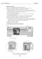
...BJC-6000 Adjustment procedure: 1) Set the 1.9-mm gap gauge (QY9-0038) in position A. 2) Move the carriage into position C by moving the carriage belt by hand. 3) Install the Black BJ cartridge on the left side of the carriage. 4) Slowly loosen, by half a turn, the fixing screw that secures the left adjustable bearing supporting... on the left side of the carriage. 10) Slowly loosen, by half a turn, the fixing screw that secures the right adjustable bearing supporting the carriage shaft, and move the paper thickness selector up and down two or three times, and tighten the fixing screw. 11) Remove...
...BJC-6000 Adjustment procedure: 1) Set the 1.9-mm gap gauge (QY9-0038) in position A. 2) Move the carriage into position C by moving the carriage belt by hand. 3) Install the Black BJ cartridge on the left side of the carriage. 4) Slowly loosen, by half a turn, the fixing screw that secures the left adjustable bearing supporting... on the left side of the carriage. 10) Slowly loosen, by half a turn, the fixing screw that secures the right adjustable bearing supporting the carriage shaft, and move the paper thickness selector up and down two or three times, and tighten the fixing screw. 11) Remove...

