
User Manual
Page 2
... Power...17 Turning on the Power of the Main Unit...17 Operating the Video Display...18 Operating the jog dial...18 Basic operations to use the OSD menu 18 Adjusting Image Quality While Viewing the Entire Image 20 Temporarily Saving Parameters (Anchor Point Setting 21 Calibration without a PC...22 Export/Import...23 Set Date/Time...25 Inputting Characters...25 Using the Function (F) Buttons...26 Using the Channel (CH) Button...27 Checking Signal Information and Status...
... Power...17 Turning on the Power of the Main Unit...17 Operating the Video Display...18 Operating the jog dial...18 Basic operations to use the OSD menu 18 Adjusting Image Quality While Viewing the Entire Image 20 Temporarily Saving Parameters (Anchor Point Setting 21 Calibration without a PC...22 Export/Import...23 Set Date/Time...25 Inputting Characters...25 Using the Function (F) Buttons...26 Using the Channel (CH) Button...27 Checking Signal Information and Status...

User Manual
Page 6
... the equipment. Turn the power off and wait until the condensation has evaporated before using the video display. 6 Handling Precautions Less than 99.99% of the pixels operating to specification. Note this equipment is brought into a warm room while it is left facing strong source of light. About the LCD screen The screen is displayed for a prolonged period, screen burn-in may change due to...
... the equipment. Turn the power off and wait until the condensation has evaporated before using the video display. 6 Handling Precautions Less than 99.99% of the pixels operating to specification. Note this equipment is brought into a warm room while it is left facing strong source of light. About the LCD screen The screen is displayed for a prolonged period, screen burn-in may change due to...
User Manual
Page 8
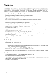
...; A color grading controller (Element-Tk made possible by Canon's image-making technology as well as builtin performance and functions suitable for shooting video. The video display provides high image quality made by using meta information of the camera. - The video display uses a 24-inch panel with a HDMI input terminal. The handle and adjustable two position stand provides flexible installation and high portability. • Supports DC power supply input. 8 Features Features Video Display DP-V2410 is a reference display suitable...
...; A color grading controller (Element-Tk made possible by Canon's image-making technology as well as builtin performance and functions suitable for shooting video. The video display provides high image quality made by using meta information of the camera. - The video display uses a 24-inch panel with a HDMI input terminal. The handle and adjustable two position stand provides flexible installation and high portability. • Supports DC power supply input. 8 Features Features Video Display DP-V2410 is a reference display suitable...

User Manual
Page 9
... menu, changes the settings (up/down, left/ 18 right, rotation) and determines (press) the selection. RESET button Resets the items to be set . 48 3 USB port Connection for an external sensor for headphone set from "Off" or "1 (dark) to F8 buttons Execute the defined function. The brightness of the power indicator can assign different functions on - Green flash: during calibration or firmware upgrade Amber lit: during firmware upgrade, or when an error...
... menu, changes the settings (up/down, left/ 18 right, rotation) and determines (press) the selection. RESET button Resets the items to be set . 48 3 USB port Connection for an external sensor for headphone set from "Off" or "1 (dark) to F8 buttons Execute the defined function. The brightness of the power indicator can assign different functions on - Green flash: during calibration or firmware upgrade Amber lit: during firmware upgrade, or when an error...

User Manual
Page 10
... output corresponding to save data on a USB memory is executed during recognition, the message "Detecting USB memory" is displayed. 10 Nomenclature terminal Af 3G/HD-SDI input Used to input SDI signals. 15 terminal Ag DC power input Connection for DC power supply. 17 terminal Ah AC power input Connection for the provided AC power supply cord. 17 terminal CAUTION • When connecting an external sensor for a Display Controller CL-01 (separately sold...
... output corresponding to save data on a USB memory is executed during recognition, the message "Detecting USB memory" is displayed. 10 Nomenclature terminal Af 3G/HD-SDI input Used to input SDI signals. 15 terminal Ag DC power input Connection for DC power supply. 17 terminal Ah AC power input Connection for the provided AC power supply cord. 17 terminal CAUTION • When connecting an external sensor for a Display Controller CL-01 (separately sold...

User Manual
Page 14
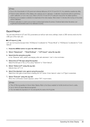
..., the operating temperature may damage it is blocked by equipment placed above and below . 4×M4 7 mm deep (Max.) 2×M4 Rear 8 mm deep (Max.) Side Same on the other side 14 Installation/Connection Screws compatible with at least two people. • When mounting the main unit on a wall, make a space of the video display (0 ˚C to check the...
..., the operating temperature may damage it is blocked by equipment placed above and below . 4×M4 7 mm deep (Max.) 2×M4 Rear 8 mm deep (Max.) Side Same on the other side 14 Installation/Connection Screws compatible with at least two people. • When mounting the main unit on a wall, make a space of the video display (0 ˚C to check the...

User Manual
Page 20
... completed, press the jog dial. The indication changes to the original OSD menu. The adjusted value is on the color map. 1. Default value Last used value Current value Current value 20 Operating the Video Display Switch the guide in "Color Temperature" on setting options. Adjust "x" with the and "y" with using the slider as a slider at the bottom of the screen. The screen returns to "RGB", "R", "G", and "B". 2. A slider appears at...
... completed, press the jog dial. The indication changes to the original OSD menu. The adjusted value is on the color map. 1. Default value Last used value Current value Current value 20 Operating the Video Display Switch the guide in "Color Temperature" on setting options. Adjust "x" with the and "y" with using the slider as a slider at the bottom of the screen. The screen returns to "RGB", "R", "G", and "B". 2. A slider appears at...

User Manual
Page 22
.... 5. When the message "Calibration is displayed. Set the mode dial of the Universal Measuring Probe to the USB port of the CA-310 and CA-210. 1. Finish calibration. is completed". Connect the display color analyzer to "0-CAL". Press the jog dial and select "Start". Press the jog dial of the video display. Calibration without a PC ( 40) When "User 1-7" under "Picture Mode" is displayed, press the jog...
.... 5. When the message "Calibration is displayed. Set the mode dial of the Universal Measuring Probe to the USB port of the CA-310 and CA-210. 1. Finish calibration. is completed". Connect the display color analyzer to "0-CAL". Press the jog dial and select "Start". Press the jog dial of the video display. Calibration without a PC ( 40) When "User 1-7" under "Picture Mode" is displayed, press the jog...
User Manual
Page 23
... file type using the jog dial. Select the color gamut used when creating the LUT (when "Color Gamut" under "LUT Type" is proprietary to Canon Video Display. When the confirmation screen appears, select "OK". Wait at least 10 minutes after turning on the power before calibration. • Perform calibration in the root folder. 4. Insert a USB memory stick into the USB port of the...
... file type using the jog dial. Select the color gamut used when creating the LUT (when "Color Gamut" under "LUT Type" is proprietary to Canon Video Display. When the confirmation screen appears, select "OK". Wait at least 10 minutes after turning on the power before calibration. • Perform calibration in the root folder. 4. Insert a USB memory stick into the USB port of the...

User Manual
Page 27
... video display by factory default. The channel name, signal information, and status of the button using the jog dial. CH Input Configuration Select Input Signal Format Internal Sync Channel Name Picture Mode Color Range CH1 3G/HD-SDI Automatic Automatic Off (Blank) ITU-R BT.709 Automatic CH2 HDMI Automatic Automatic Off (Blank) ITU-R BT.709 Automatic CH3 3G-SDI RAW Automatic Automatic Off (Blank) Canon Log Automatic Checking Signal...
... video display by factory default. The channel name, signal information, and status of the button using the jog dial. CH Input Configuration Select Input Signal Format Internal Sync Channel Name Picture Mode Color Range CH1 3G/HD-SDI Automatic Automatic Off (Blank) ITU-R BT.709 Automatic CH2 HDMI Automatic Automatic Off (Blank) ITU-R BT.709 Automatic CH3 3G-SDI RAW Automatic Automatic Off (Blank) Canon Log Automatic Checking Signal...

User Manual
Page 34
... displayed content. Adjusts the white level of the image. (Increments of each setting. The backlight of light emitted by the backlight on the image. If the image is dark, the whole display is selected, the contrast may change the mode name within 16 one-byte characters including alphabetical characters, numbers, and symbols. Item Picture Mode Contrast Brightness Chroma Sharpness Backlight Control Setting Options (underline indicates factory default) Select a preset mode...
... displayed content. Adjusts the white level of the image. (Increments of each setting. The backlight of light emitted by the backlight on the image. If the image is dark, the whole display is selected, the contrast may change the mode name within 16 one-byte characters including alphabetical characters, numbers, and symbols. Item Picture Mode Contrast Brightness Chroma Sharpness Backlight Control Setting Options (underline indicates factory default) Select a preset mode...
User Manual
Page 35
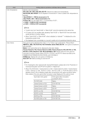
... increments of the color gamut after adjusting "Gain R/G/B" or "Bias R/G/B" then both these values will return to the "Parameter of Cinema EOS System and DP-V2410 ( 58)" in increments of ACESproxy. User LUT 1-8: Sets by color temperature preset mode. • The displayed color coordinates (x, y) are modified after conversion is displayed by loading an external LUT. Item Color Temperature Color Gamut Setting Options (underline indicates factory default) Sets the color temperature. Input video color gamut ITU...
... increments of the color gamut after adjusting "Gain R/G/B" or "Bias R/G/B" then both these values will return to the "Parameter of Cinema EOS System and DP-V2410 ( 58)" in increments of ACESproxy. User LUT 1-8: Sets by color temperature preset mode. • The displayed color coordinates (x, y) are modified after conversion is displayed by loading an external LUT. Item Color Temperature Color Gamut Setting Options (underline indicates factory default) Sets the color temperature. Input video color gamut ITU...

User Manual
Page 44
... 1 (16-235)" is set 44 OSD Menu "Limited 1 (16-235)" is set automatically depending on signal information automatically. Off: Do not force synchronization. Sets the "Picture Mode". The factory default settings for "Color Gamut". • Operations when "Automatic" is shown in the other cases. Automatic: Sets the range based on HDMI signal information. -- Black level: 64 (10-bit)/256 (12-bit) White level: 1023 (10-bit...
... 1 (16-235)" is set 44 OSD Menu "Limited 1 (16-235)" is set automatically depending on signal information automatically. Off: Do not force synchronization. Sets the "Picture Mode". The factory default settings for "Color Gamut". • Operations when "Automatic" is shown in the other cases. Automatic: Sets the range based on HDMI signal information. -- Black level: 64 (10-bit)/256 (12-bit) White level: 1023 (10-bit...

User Manual
Page 57
... of channels displayed when SDI signal is executed OSD Menu 57 When "Reset All Settings" is input. Item Audio Level Meter Setting Options (underline indicates factory default) Configures various settings for Channel UP/ Channel DOWN, or "Select Channel" under "Channel Settings" - When changing "Input Configuration" or "Select Input Signal" under "Screen Capture", or when "Test Pattern" is changed using the CH button, F button assigned for the audio level meter. Note • "Audio Level Meter...
... of channels displayed when SDI signal is executed OSD Menu 57 When "Reset All Settings" is input. Item Audio Level Meter Setting Options (underline indicates factory default) Configures various settings for Channel UP/ Channel DOWN, or "Select Channel" under "Channel Settings" - When changing "Input Configuration" or "Select Input Signal" under "Screen Capture", or when "Test Pattern" is changed using the CH button, F button assigned for the audio level meter. Note • "Audio Level Meter...
User Manual
Page 62
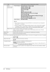
.... Firmware Update This function is , the greater the brightness. Select a CH button and register a channel number. A list of settings under the currently selected "Marker Preset". Power Indicator Brightness Adjusts the brightness of the main unit. Normal: All formats are changed, those changes will be applied to the CH button on the main unit. Item Display Function/Display Function (CDL) Function Settings System Settings Setting Options (underline indicates factory default...
.... Firmware Update This function is , the greater the brightness. Select a CH button and register a channel number. A list of settings under the currently selected "Marker Preset". Power Indicator Brightness Adjusts the brightness of the main unit. Normal: All formats are changed, those changes will be applied to the CH button on the main unit. Item Display Function/Display Function (CDL) Function Settings System Settings Setting Options (underline indicates factory default...
User Manual
Page 84
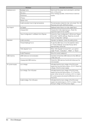
.... Reset any incorrect "Input Configuration" settings. Check the setting items. To use the OSD menu, move the selection frame to high temperature. Check the voltage of the DC power supply. 84 Error Messages Connect a 23.5 V or higher DC power supply and press the button to the USB port of the DC power supply has become below approx. 21.0 V and the power will be turned off power. Indicates that the input voltage of this main unit. Hardware error Input signal Message Backlight error. Operation...
.... Reset any incorrect "Input Configuration" settings. Check the setting items. To use the OSD menu, move the selection frame to high temperature. Check the voltage of the DC power supply. 84 Error Messages Connect a 23.5 V or higher DC power supply and press the button to the USB port of the DC power supply has become below approx. 21.0 V and the power will be turned off power. Indicates that the input voltage of this main unit. Hardware error Input signal Message Backlight error. Operation...

User Manual
Page 85
... unlit or red, blue, green, or • LCD display is a characteristic of 99.99% or more . green dots that may be resolved by displaying a white or black image on that remains when the LCD panel is connected correctly. Troubleshooting 85 The screen is lit orange: 9 • Press the button. When the power indicator is dark. Check the signal. When the power indicator does not turn on operation environment. displayed. If the screen becomes dark or starts flickering, contact Canon Customer...
... unlit or red, blue, green, or • LCD display is a characteristic of 99.99% or more . green dots that may be resolved by displaying a white or black image on that remains when the LCD panel is connected correctly. Troubleshooting 85 The screen is lit orange: 9 • Press the button. When the power indicator is dark. Check the signal. When the power indicator does not turn on operation environment. displayed. If the screen becomes dark or starts flickering, contact Canon Customer...

User Manual
Page 86
... • Check the "Power on Setting" on the OSD menu. Check the signal. The fan starts to rotate even when "Fan" • The fan stays off to "On". • The fan may be reset to the state where no signal, unsupported signal, or with no password is set to start up the video display in some conditions, for a longer period, use a DC power supply. Configure settings after the internal temperature has lowered. Use the video display at a 63 high temperature.
... • Check the "Power on Setting" on the OSD menu. Check the signal. The fan starts to rotate even when "Fan" • The fan stays off to "On". • The fan may be reset to the state where no signal, unsupported signal, or with no password is set to start up the video display in some conditions, for a longer period, use a DC power supply. Configure settings after the internal temperature has lowered. Use the video display at a 63 high temperature.
User Manual
Page 92
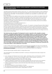
... the Equipment is used in the event of failure or other proof of the Equipment in Canon USA's user's manual; The sole warranty with respect to Canon Professional Display Equipment (the 'Equipment') accompanying this limited warranty for a period of the problem. Technical support program specifics subject to product hardware or firmware; D. Any internal modification to change without notice. USA CANON PROFESSIONAL DISPLAY LIMITED WARRANTY...
... the Equipment is used in the event of failure or other proof of the Equipment in Canon USA's user's manual; The sole warranty with respect to Canon Professional Display Equipment (the 'Equipment') accompanying this limited warranty for a period of the problem. Technical support program specifics subject to product hardware or firmware; D. Any internal modification to change without notice. USA CANON PROFESSIONAL DISPLAY LIMITED WARRANTY...
User Manual
Page 94
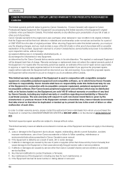
... the Equipment in Canon Canada's users manual; If the Equipment has had its original container, that cause abnormally frequent service calls or service problems D. CANADA CANON PROFESSIONAL DISPLAY LIMITED WARRANTY FOR PRODUCTS PURCHASED IN CANADA The limited warranty set forth below is given by Canon Canada Inc. ('Canon Canada') with incompatible computer equipment, peripheral equipment and/or incompatible software. For repairs after the...
... the Equipment in Canon Canada's users manual; If the Equipment has had its original container, that cause abnormally frequent service calls or service problems D. CANADA CANON PROFESSIONAL DISPLAY LIMITED WARRANTY FOR PRODUCTS PURCHASED IN CANADA The limited warranty set forth below is given by Canon Canada Inc. ('Canon Canada') with incompatible computer equipment, peripheral equipment and/or incompatible software. For repairs after the...


