
Instruction Manual
Page 2
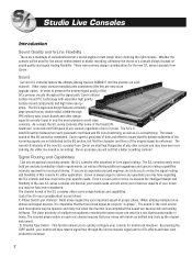
... not find a better sounding console! The S/L consoles easily meet all your specific needs. Even if you to answer any exceptional recording console, the S/L consoles offer advanced In-Line signal routing. The channel phase switch on each channel). This function allows you are just a novice, be overstated. By pressing the TAPE switch, your console for either live sound or recording), Carvin promises you may not have been considering (for live sound mixing.
... not find a better sounding console! The S/L consoles easily meet all your specific needs. Even if you to answer any exceptional recording console, the S/L consoles offer advanced In-Line signal routing. The channel phase switch on each channel). This function allows you are just a novice, be overstated. By pressing the TAPE switch, your console for either live sound or recording), Carvin promises you may not have been considering (for live sound mixing.

Instruction Manual
Page 3
... Carvin S/L series consoles! 4) Channel Solo & PFL - For most recording situations, the input tape switch will be depressed for buses 5&6 (for the studio headphone mixes) and for buses 7&8 for either the tape input signal or the mic input to these extremely versatile consoles in this switch will allow our product experts help direct you may wish to the console's L/R master faders. Yet another advanced feature of the S/L series consoles. You can select the L/R switch...
... Carvin S/L series consoles! 4) Channel Solo & PFL - For most recording situations, the input tape switch will be depressed for buses 5&6 (for the studio headphone mixes) and for buses 7&8 for either the tape input signal or the mic input to these extremely versatile consoles in this switch will allow our product experts help direct you may wish to the console's L/R master faders. Yet another advanced feature of the S/L series consoles. You can select the L/R switch...
Instruction Manual
Page 5
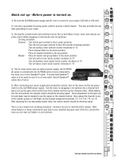
... the master groups or Left-Right via the channel assignment switches 1-2, 3-4, 5-6, 7-8, or L-R. Not all master and group faders to "0". Some adjustment to the gain control and fader may help in your mixer and reduces surprises when initially plugging in turn connected to the mixer via the red power switch on the channel meters. Now assign the channel to the SLP5600 and is a 4 wire cable. Turn all channel switches to "0". 4) The SL mixer series uses an external power supply, the SLP5600. AC power is connected to...
... the master groups or Left-Right via the channel assignment switches 1-2, 3-4, 5-6, 7-8, or L-R. Not all master and group faders to "0". Some adjustment to the gain control and fader may help in your mixer and reduces surprises when initially plugging in turn connected to the mixer via the red power switch on the channel meters. Now assign the channel to the SLP5600 and is a 4 wire cable. Turn all channel switches to "0". 4) The SL mixer series uses an external power supply, the SLP5600. AC power is connected to...
Instruction Manual
Page 6
Master Section pg 11 Master I/O section Left, Right, and Groups Control Masters Stereo Returns & Tape IN/OUT Auxiliary Send Masters 5. Standard Studio Mixer Setups . . . .pg 14 6. Power Supply pg 24 10. General Specifications pg 27 Appendixes B. Input Channel Section pg 8 4. Using the Inserts pg 22 Standard Inserting Insert as Direct Mic-pre Out 8. Cable Connections pg 25 11. Schematics pgs 28-33 C. Standard Live Mixer Setups . . . . .pg 17 7. Block Diagram pg 26 12. Glossary of Terms pgs 35-37 6 Installation pg 7 3. Console Dimensions pg...
Master Section pg 11 Master I/O section Left, Right, and Groups Control Masters Stereo Returns & Tape IN/OUT Auxiliary Send Masters 5. Standard Studio Mixer Setups . . . .pg 14 6. Power Supply pg 24 10. General Specifications pg 27 Appendixes B. Input Channel Section pg 8 4. Using the Inserts pg 22 Standard Inserting Insert as Direct Mic-pre Out 8. Cable Connections pg 25 11. Schematics pgs 28-33 C. Standard Live Mixer Setups . . . . .pg 17 7. Block Diagram pg 26 12. Glossary of Terms pgs 35-37 6 Installation pg 7 3. Console Dimensions pg...
Instruction Manual
Page 7
.... 1. Installations The S/L series console dimensions are equipped with : • 24, 40, 56 channel frames. • Low noise mic-pre amps EIN=128dB min. • 4 band, dual mid sweep, Channel EQ. • 8 auxiliary sends: 2 pre, 2 pre/post, 2 post, (stereo) pre/post fader. • 4 stereo returns w/ Aux 1 & 2 sends, pan and level. • 8 master groups w/ L-R, assignment and pan, mute and solo. • Comprehensive master control room section with AC power try to avoid using the same power outlets used for the individual channel outputs to potential noise...
.... 1. Installations The S/L series console dimensions are equipped with : • 24, 40, 56 channel frames. • Low noise mic-pre amps EIN=128dB min. • 4 band, dual mid sweep, Channel EQ. • 8 auxiliary sends: 2 pre, 2 pre/post, 2 post, (stereo) pre/post fader. • 4 stereo returns w/ Aux 1 & 2 sends, pan and level. • 8 master groups w/ L-R, assignment and pan, mute and solo. • Comprehensive master control room section with AC power try to avoid using the same power outlets used for the individual channel outputs to potential noise...

Instruction Manual
Page 8
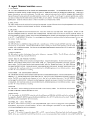
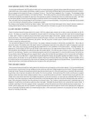
... phantom power for connecting professional low impedance microphones. +48V Phantom power is typically used at the beginning of the S/L series consoles. The 48V switch should not be used for mixing. 3. The LINE IN connectors are for condenser mics in the units output. The DIRECT OUT provides an output of 8 channels. The TAPE IN input jack makes up , please see section 7 Using the Insert Jacks on the tape switch position) and before the EQ and AUX sends. These Mic inputs...
... phantom power for connecting professional low impedance microphones. +48V Phantom power is typically used at the beginning of the S/L series consoles. The 48V switch should not be used for mixing. 3. The LINE IN connectors are for condenser mics in the units output. The DIRECT OUT provides an output of 8 channels. The TAPE IN input jack makes up , please see section 7 Using the Insert Jacks on the tape switch position) and before the EQ and AUX sends. These Mic inputs...
Instruction Manual
Page 9
... (AUX 7-8) switches. In the down position AUX 3 and AUX 4 send controls, are pre EQ, pre mute and pre fader (working the same as uninterrupted monitoring feeds for professional low impedance microphones. In a recording situation, the switch up until it is OK. Use the LOW CUT filter to achieve a natural 500 200 1k FREQ sound for normal operation. 9. MID -15 +15 vides an overall 30 dB range of the channels high gain microphone pre-amplifier. Only use these controls to...
... (AUX 7-8) switches. In the down position AUX 3 and AUX 4 send controls, are pre EQ, pre mute and pre fader (working the same as uninterrupted monitoring feeds for professional low impedance microphones. In a recording situation, the switch up until it is OK. Use the LOW CUT filter to achieve a natural 500 200 1k FREQ sound for normal operation. 9. MID -15 +15 vides an overall 30 dB range of the channels high gain microphone pre-amplifier. Only use these controls to...

Instruction Manual
Page 10
... the GAIN control to change the SOLO mode is linked to the TAPE switch at the top of AUX 7 and AUX 8 level controls are post EQ and post fader sends when the TAPE and PRE FAD w/ EQ switches are sourced after fader" where the channel's pan position is typically used for adjusting the stereo field for the channel. See Standard Live mixer setups for more details on AUX 7 and AUX 8. 3 24. The meter bridge and direct outputs...
... the GAIN control to change the SOLO mode is linked to the TAPE switch at the top of AUX 7 and AUX 8 level controls are post EQ and post fader sends when the TAPE and PRE FAD w/ EQ switches are sourced after fader" where the channel's pan position is typically used for adjusting the stereo field for the channel. See Standard Live mixer setups for more details on AUX 7 and AUX 8. 3 24. The meter bridge and direct outputs...
Instruction Manual
Page 11
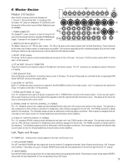
... channel L-R assignment switches, Stereo Returns and the Group 1-8 L-R assignment switches. POWER CONNECTOR 6 AUX SEND 5 6 The Speakon™ power connector is the same as a TRS L/R stereo connection for the STUDIO section of the control room and Studio Right jacks used for the 1-8 Groups. The Group 1-4 XLR's are wired so the signal will not effect the XLR balanced outputs. 3. Aux 1-4 outputs are also used , the jacks are also used to the AUX SENDS controls in the master section. Both outputs are post L-R master INSERTS and provide the level adjustments...
... channel L-R assignment switches, Stereo Returns and the Group 1-8 L-R assignment switches. POWER CONNECTOR 6 AUX SEND 5 6 The Speakon™ power connector is the same as a TRS L/R stereo connection for the STUDIO section of the control room and Studio Right jacks used for the 1-8 Groups. The Group 1-4 XLR's are wired so the signal will not effect the XLR balanced outputs. 3. Aux 1-4 outputs are also used , the jacks are also used to the AUX SENDS controls in the master section. Both outputs are post L-R master INSERTS and provide the level adjustments...
Instruction Manual
Page 12
... muted. For normal solos the meters indicate stereo in place material, when using the control room right output for the solo circuit in -place solo switches to the post TAPE IN level input. L-R: listens to the final output of both the Control Room outputs and the Studio outputs for PHONES. 23. Control Masters 13. MONO: creates a control room left , the right, or any PAN setting of the AUX 1-2 masters. STUDIO LEVEL The STUDIO level adjusts the level...
... muted. For normal solos the meters indicate stereo in place material, when using the control room right output for the solo circuit in -place solo switches to the post TAPE IN level input. L-R: listens to the final output of both the Control Room outputs and the Studio outputs for PHONES. 23. Control Masters 13. MONO: creates a control room left , the right, or any PAN setting of the AUX 1-2 masters. STUDIO LEVEL The STUDIO level adjusts the level...

Instruction Manual
Page 13
... IN jacks. 32. STEREO RETURN MUTE AND SOLO Each stereo return contains a MUTE and a SOLO switch. The MUTE switch is sent to the main L-R mix. TAPE IN LEVEL This adjusts the level of the RCA TAPE IN signal through the AUX 7-8 sends. 31. The stereo return PAN works as a balance control for Stereo inputs and as the MUTE (post PAN and LEVEL). 30. At the same time, the affected group output is the main level control for secondary channel inputs to...
... IN jacks. 32. STEREO RETURN MUTE AND SOLO Each stereo return contains a MUTE and a SOLO switch. The MUTE switch is sent to the main L-R mix. TAPE IN LEVEL This adjusts the level of the RCA TAPE IN signal through the AUX 7-8 sends. 31. The stereo return PAN works as a balance control for Stereo inputs and as the MUTE (post PAN and LEVEL). 30. At the same time, the affected group output is the main level control for secondary channel inputs to...
Instruction Manual
Page 14
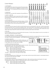
... Aux 7-8 TAPE switch. The MIC input can be left connected in both used in the mix down (where all the Auxiliaries, the Fader, the DIRECT OUTPUT and Bus assignments. One of the connections described here can be used . With the use , many of the key points here is the typical setup for the two modes internally. Figure 5-1 shows a block diagram of the channel and the modes of the S/L series console. In the example the multi-track recorder...
... Aux 7-8 TAPE switch. The MIC input can be left connected in both used in the mix down (where all the Auxiliaries, the Fader, the DIRECT OUTPUT and Bus assignments. One of the connections described here can be used . With the use , many of the key points here is the typical setup for the two modes internally. Figure 5-1 shows a block diagram of the channel and the modes of the S/L series console. In the example the multi-track recorder...
Instruction Manual
Page 15
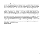
... the Carvin PB48 patch bay . In these cases, the Groups are patched for tracking. Even in -line and split recording setups using a different channel or bus for mixing than was used for tracking goes direct to the multi-track recorder. Using the patch bay allows the busses to the outputs of the mixer are connected with the inputs from the mics and instruments being used for tape outputs. see figure 5-3 on the mixing consoles setup and...
... the Carvin PB48 patch bay . In these cases, the Groups are patched for tracking. Even in -line and split recording setups using a different channel or bus for mixing than was used for tracking goes direct to the multi-track recorder. Using the patch bay allows the busses to the outputs of the mixer are connected with the inputs from the mics and instruments being used for tape outputs. see figure 5-3 on the mixing consoles setup and...
Instruction Manual
Page 17
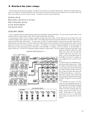
... pre fader mode (via the PRE switch down) and the AUX 7/8 sends in the pre-fader / post EQ mode (via the AUX 7/8 TAPE switch in the down position) and in the master section by the AUX 7/8 L-R switch. This is best these input signals are : Auxiliary sends Recording a live shows when channeled through the AUX 7/8 send (via the PRE w/EQ switch down as 3 individual front-of the S/L series console. The Auxiliary 1-4 sends are made up of having 6 pre-fader sends. MONITOR MIX 3 Power Amp Power Amp 0 1 10 PRE...
... pre fader mode (via the PRE switch down) and the AUX 7/8 sends in the pre-fader / post EQ mode (via the AUX 7/8 TAPE switch in the down position) and in the master section by the AUX 7/8 L-R switch. This is best these input signals are : Auxiliary sends Recording a live shows when channeled through the AUX 7/8 send (via the PRE w/EQ switch down as 3 individual front-of the S/L series console. The Auxiliary 1-4 sends are made up of having 6 pre-fader sends. MONITOR MIX 3 Power Amp Power Amp 0 1 10 PRE...
Instruction Manual
Page 19
... control for stereo). Good positioning of the monitors and the use of a graphic equalizer solves most major monitor feedback problems. Now for four stage monitor mixes via the AUX 1-4 FLIP switches. SUB MIXING WITH THE GROUPS For live setup with the S/L console. This is why the Keyboard is where several channels. The 6 XLR outputs connected at the 1-4 XLR GROUP OUTPUTS and LEFT/RIGHT master outputs are included in the sound check. First set the level...
... control for stereo). Good positioning of the monitors and the use of a graphic equalizer solves most major monitor feedback problems. Now for four stage monitor mixes via the AUX 1-4 FLIP switches. SUB MIXING WITH THE GROUPS For live setup with the S/L console. This is why the Keyboard is where several channels. The 6 XLR outputs connected at the 1-4 XLR GROUP OUTPUTS and LEFT/RIGHT master outputs are included in the sound check. First set the level...
Instruction Manual
Page 22
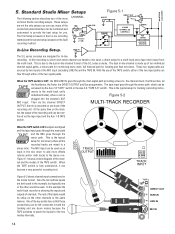
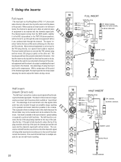
... the ground connected to go through one end the TRS (stereo) plug and two mono (TS) plugs (or jacks) on the same channel, special cabling is popular when recording tracks in multi-track recording. 22 15 DIRECT OUT TAPE IN LINE IN MIC INSERT FULL INSERT TAPE Pre-Amp TIP RING TIP RING MIC Pre-Amp PIN 2 (+) PIN 3 (-) GAIN TAPE SWITCH TIP: SEND SIGNAL RING: RETURN SIGNAL SLEEVE: GROUND GAIN PHASE TAPE 4 55 0 -15 +15 HIGH 0 -15 +15 LOW CUT...
... the ground connected to go through one end the TRS (stereo) plug and two mono (TS) plugs (or jacks) on the same channel, special cabling is popular when recording tracks in multi-track recording. 22 15 DIRECT OUT TAPE IN LINE IN MIC INSERT FULL INSERT TAPE Pre-Amp TIP RING TIP RING MIC Pre-Amp PIN 2 (+) PIN 3 (-) GAIN TAPE SWITCH TIP: SEND SIGNAL RING: RETURN SIGNAL SLEEVE: GROUND GAIN PHASE TAPE 4 55 0 -15 +15 HIGH 0 -15 +15 LOW CUT...

Instruction Manual
Page 24
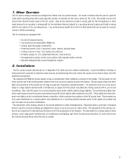
... proper cable connections. SPECIFICATIONS Mixer Connection The SLP5600 is a two space rack mountable power supply which indicates the mixer is a thermal metal breaker, so it may remain on the rear panel. These LEDs are over loaded and tripped. SSLL 660000 PP- 5- 5 S/SL/LSeSreiersiePsoPwoewreSr uSpupplyply 10 A M P 120VAC 60Hz 300VA The SL series consoles use the SLP5600 external power supply. Now turn on mode. 24 The Speakon™ connector is the lighted power switch...
... proper cable connections. SPECIFICATIONS Mixer Connection The SLP5600 is a two space rack mountable power supply which indicates the mixer is a thermal metal breaker, so it may remain on the rear panel. These LEDs are over loaded and tripped. SSLL 660000 PP- 5- 5 S/SL/LSeSreiersiePsoPwoewreSr uSpupplyply 10 A M P 120VAC 60Hz 300VA The SL series consoles use the SLP5600 external power supply. Now turn on mode. 24 The Speakon™ connector is the lighted power switch...
Instruction Manual
Page 35
... making sure you are typically powered by internal batteries or "phantom power" supplied by the equation dB=20Log 10 (V 1 /V 2 ). Cueing In broadcast, stage and post-production work , delay usually refers to a type of the mixing console rather than 3dB, expressed in the ratio is the same as a capacitor. It does not go out on the capacitor. Direct output A post fader line level output from each wire. Dynamic...
... making sure you are typically powered by internal batteries or "phantom power" supplied by the equation dB=20Log 10 (V 1 /V 2 ). Cueing In broadcast, stage and post-production work , delay usually refers to a type of the mixing console rather than 3dB, expressed in the ratio is the same as a capacitor. It does not go out on the capacitor. Direct output A post fader line level output from each wire. Dynamic...
Instruction Manual
Page 36
.... Monitor speakers are producing. EIN (Equivalent Input Noise) A specification that functions to bring the very low signal level of a microphone (approximately -50dBu) up to reduce ground loop noise problems. Ground loop A ground loop occurs when the technical ground within a system or a single device. Headroom The available signal range above the nominal level before clipping occurs. eral master controls, which the time of arrival of a sound to be used by...
.... Monitor speakers are producing. EIN (Equivalent Input Noise) A specification that functions to bring the very low signal level of a microphone (approximately -50dBu) up to reduce ground loop noise problems. Ground loop A ground loop occurs when the technical ground within a system or a single device. Headroom The available signal range above the nominal level before clipping occurs. eral master controls, which the time of arrival of a sound to be used by...
Instruction Manual
Page 37
... section independently. If this is for insert jacks, used to connect phonographs to receive the output of two audio signals. A peaking EQ centered at the channel mic inputs, for connecting two conductors through a single plug or jack. Often mixers use the term Aux Send for connecting three conductors through a single plug or jack. Shelving An equalizer response affecting all frequencies above or below the level of measurements include average volts, peak...
... section independently. If this is for insert jacks, used to connect phonographs to receive the output of two audio signals. A peaking EQ centered at the channel mic inputs, for connecting two conductors through a single plug or jack. Often mixers use the term Aux Send for connecting three conductors through a single plug or jack. Shelving An equalizer response affecting all frequencies above or below the level of measurements include average volts, peak...


