PD752KEV Owners Manual Manual
Page 1
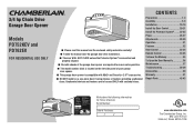
Date of Purchase: www.chamberlain.com The Chamberlain Group, Inc. 845 Larch Avenue Elmhurst, Illinois 60126-1196 CONTENTS Preparation 1-4 Assembly 5-9 Installation 10-19 Install the Door Control 20-21 Install the Protector System® ...... 22-25 Power 26-27 Adjustments 28-30 Operation 31 Features 32 ...MyQ® and Security+ 2.0™ accessories. ■ DO NOT install on a one-piece door if using devices or features providing unattended close. 3/4 hp Chain Drive Garage Door Opener Models PD752KEV and PD762EV FOR RESIDENTIAL USE ONLY ■ Please read this manual and the ...
Date of Purchase: www.chamberlain.com The Chamberlain Group, Inc. 845 Larch Avenue Elmhurst, Illinois 60126-1196 CONTENTS Preparation 1-4 Assembly 5-9 Installation 10-19 Install the Door Control 20-21 Install the Protector System® ...... 22-25 Power 26-27 Adjustments 28-30 Operation 31 Features 32 ...MyQ® and Security+ 2.0™ accessories. ■ DO NOT install on a one-piece door if using devices or features providing unattended close. 3/4 hp Chain Drive Garage Door Opener Models PD752KEV and PD762EV FOR RESIDENTIAL USE ONLY ■ Please read this manual and the ...
PD752KEV Owners Manual Manual
Page 2
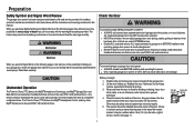
...the way of the header bracket, it is out of the door. Otherwise, the safety reversal system may NOT reverse when required. l DO NOT install on the following pages, it will alert you to the possibility of serious injury or death if you see these Safety Symbols and Signal Words...may come from something mechanical or from electric shock. Read the warnings carefully. Disable locks and remove any other MyQ® devices are to be installed above the center of the door must not exceed 1/4 inch (6 mm). Lift the door halfway up. Any gap between the floor and the bottom...
...the way of the header bracket, it is out of the door. Otherwise, the safety reversal system may NOT reverse when required. l DO NOT install on the following pages, it will alert you to the possibility of serious injury or death if you see these Safety Symbols and Signal Words...may come from something mechanical or from electric shock. Read the warnings carefully. Disable locks and remove any other MyQ® devices are to be installed above the center of the door must not exceed 1/4 inch (6 mm). Lift the door halfway up. Any gap between the floor and the bottom...
PD752KEV Owners Manual Manual
Page 3
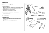
Also used to install the safety reversing sensor. n RAIL EXTENSION KIT Required if your garage door is more than 7 feet (2.13 m) high. Tools Needed 5/32 3/16 5/16 1/2 5/8 1/4 7/16 9/16 7/... the safety reversing sensor will need any of the following items: n (2) 2X4 PIECES OF WOOD May be needed to position the garage door opener during installation and for testing the safety reversing sensors. Preparation Additional Items You May Need: Survey your garage area to see if you will require hardware not...
Also used to install the safety reversing sensor. n RAIL EXTENSION KIT Required if your garage door is more than 7 feet (2.13 m) high. Tools Needed 5/32 3/16 5/16 1/2 5/8 1/4 7/16 9/16 7/... the safety reversing sensor will need any of the following items: n (2) 2X4 PIECES OF WOOD May be needed to position the garage door opener during installation and for testing the safety reversing sensors. Preparation Additional Items You May Need: Survey your garage area to see if you will require hardware not...

PD752KEV Owners Manual Manual
Page 4
... front rail section) F. Chain and cable N. Depending on the garage door opener model purchased. Door bracket D. "U" bracket M. Save the carton and packing material until the installation and adjustment is packaged in this manual. The Protector System® Safety reversing sensors with screws L. Emergency release rope and handle H. Rail (1 front and 4 center...
... front rail section) F. Chain and cable N. Depending on the garage door opener model purchased. Door bracket D. "U" bracket M. Save the carton and packing material until the installation and adjustment is packaged in this manual. The Protector System® Safety reversing sensors with screws L. Emergency release rope and handle H. Rail (1 front and 4 center...
PD752KEV Owners Manual Manual
Page 5
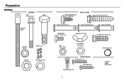
Preparation Hardware ASSEMBLY Bolt Bolt 1/4"-20x1-3/4" Threaded Shaft Lock Nut 1/4"-20 Master Link Nut 3/8" Lock Washer 3/8" Self-Threading Screw 1/4"-14x5/8" (2) INSTALLATION Lag Screw 5/16"-9x1-5/8" (4) Clevis Pin 5/16"x1-1/2" Clevis Pin 5/16"x1-1/4" Clevis Pin 5/16"x1" Carriage Bolt 1/4"-20x1/2" (2) Nut 5/16"-18 (6) Wing Nut 1/4"-20 (2) Lock Washer 5/16"-18 (5) Hex Bolt 5/16"-18x7/8" (4) Ring Fastener (3) DOOR CONTROL Screw 6-32x1" (2) Drywall Anchors (2) Screw 6ABx1" (2) 4 Insulated Staples (Not Shown)
Preparation Hardware ASSEMBLY Bolt Bolt 1/4"-20x1-3/4" Threaded Shaft Lock Nut 1/4"-20 Master Link Nut 3/8" Lock Washer 3/8" Self-Threading Screw 1/4"-14x5/8" (2) INSTALLATION Lag Screw 5/16"-9x1-5/8" (4) Clevis Pin 5/16"x1-1/2" Clevis Pin 5/16"x1-1/4" Clevis Pin 5/16"x1" Carriage Bolt 1/4"-20x1/2" (2) Nut 5/16"-18 (6) Wing Nut 1/4"-20 (2) Lock Washer 5/16"-18 (5) Hex Bolt 5/16"-18x7/8" (4) Ring Fastener (3) DOOR CONTROL Screw 6-32x1" (2) Drywall Anchors (2) Screw 6ABx1" (2) 4 Insulated Staples (Not Shown)
PD752KEV Owners Manual Manual
Page 6
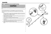
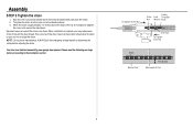
...SLIDE TO STOPS ON TOP AND SIDES OF "U" BRACKET "U" Bracket To garage door opener (TO MOTOR UNIT) Trolley Assembly STEP 1 Assemble the rail and install the trolley To prevent INJURY from pinching, keep hands and fingers away from the motor unit, as shown. 5. For convenience, put a support under the...and slide the tapered ends into the hole in the second rail section from the joints while assembling the rail. Outer Trolley To avoid installation difficulties, do not run the garage door opener until it reaches all packing material. Tabs along the side will lock into position as ...
...SLIDE TO STOPS ON TOP AND SIDES OF "U" BRACKET "U" Bracket To garage door opener (TO MOTOR UNIT) Trolley Assembly STEP 1 Assemble the rail and install the trolley To prevent INJURY from pinching, keep hands and fingers away from the motor unit, as shown. 5. For convenience, put a support under the...and slide the tapered ends into the hole in the second rail section from the joints while assembling the rail. Outer Trolley To avoid installation difficulties, do not run the garage door opener until it reaches all packing material. Tabs along the side will lock into position as ...
PD752KEV Owners Manual Manual
Page 8
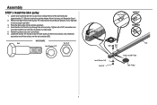
... is compressed. 5. HARDWARE Bolt Nut 3/8" Lock Washer 3/8" Rail Tab CORRECT INCORRECT Rail Bolt Rail Tab Lock Washer 3/8" Nut 3/8" Grease Inside Pulley Idler Pulley 7 Assembly STEP 3 Install the idler pulley 1. Allow it spins freely. 6. Use a flathead screwdriver and lift the rail tab until Assembly Step 4. 2. Lay the chain/cable beside the rail...
... is compressed. 5. HARDWARE Bolt Nut 3/8" Lock Washer 3/8" Rail Tab CORRECT INCORRECT Rail Bolt Rail Tab Lock Washer 3/8" Nut 3/8" Grease Inside Pulley Idler Pulley 7 Assembly STEP 3 Install the idler pulley 1. Allow it spins freely. 6. Use a flathead screwdriver and lift the rail tab until Assembly Step 4. 2. Lay the chain/cable beside the rail...
PD752KEV Owners Manual Manual
Page 9
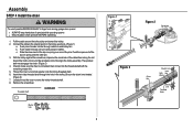
... of the clip-on the trolley, as shown. (Figure 1) a. With the trolley against the screwdriver, dispense the remainder of sprocket while operating opener. b. c. b. Assembly STEP 4 Install the chain To avoid possible SERIOUS INJURY to finger from moving garage door opener: l ALWAYS keep hand clear of the cable/chain along the rail...
... of the clip-on the trolley, as shown. (Figure 1) a. With the trolley against the screwdriver, dispense the remainder of sprocket while operating opener. b. c. b. Assembly STEP 4 Install the chain To avoid possible SERIOUS INJURY to finger from moving garage door opener: l ALWAYS keep hand clear of the cable/chain along the rail...
PD752KEV Owners Manual Manual
Page 10
... can result if the chain is approximately 1/4" (6 mm) above the base of Rail 9 When the chain is too loose. When installation is normal. Please read the following warnings before adjusting the chain. NOTE: During future maintenance, ALWAYS pull the emergency release handle to disconnect... the trolley before proceeding to the installation section. To Tighten Outer Nut Trolley Outer Lock Threaded Nut Washer Shaft Inner Nut To Tighten Inner Nut Chain Base of Rail ...
... can result if the chain is approximately 1/4" (6 mm) above the base of Rail 9 When the chain is too loose. When installation is normal. Please read the following warnings before adjusting the chain. NOTE: During future maintenance, ALWAYS pull the emergency release handle to disconnect... the trolley before proceeding to the installation section. To Tighten Outer Nut Trolley Outer Lock Threaded Nut Washer Shaft Inner Nut To Tighten Inner Nut Chain Base of Rail ...
PD752KEV Owners Manual Manual
Page 11
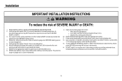
... feet (1.83 m) above floor. 6. Unattended devices and features are to garage door control. 11. NEVER wear watches, rings or loose clothing while installing or servicing opener. They could result in plain view on the floor. 13. Upon completion of SEVERE INJURY or DEATH: 1. NEVER connect garage door ... of garage door. 12. Door MUST reverse on contact with sectional doors. 10 Mount the emergency release within sight of the door. 10. Install garage door opener 7 feet (2.13 m) or more above the floor and avoiding contact with vehicles to do so. 8. To avoid SERIOUS PERSONAL...
... feet (1.83 m) above floor. 6. Unattended devices and features are to garage door control. 11. NEVER wear watches, rings or loose clothing while installing or servicing opener. They could result in plain view on the floor. 13. Upon completion of SEVERE INJURY or DEATH: 1. NEVER connect garage door ... of garage door. 12. Door MUST reverse on contact with sectional doors. 10 Mount the emergency release within sight of the door. 10. Install garage door opener 7 feet (2.13 m) or more above the floor and avoiding contact with vehicles to do so. 8. To avoid SERIOUS PERSONAL...
PD752KEV Owners Manual Manual
Page 12
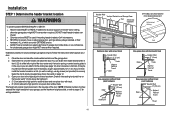
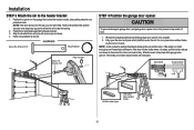
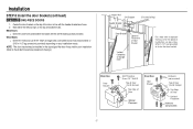
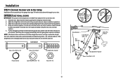
...Wall 2" (5 cm) Door Track Highest Point of Travel Pivot Open your door to the highest point of travel clearance for ceiling installation. 11 Header Wall Vertical Centerline of Garage Door 2x4 Structural Supports OPTIONAL CEILING MOUNT FOR HEADER BRACKET Unfinished Ceiling Level (...or center bearing plate is minimal. (It may be mounted on the wall upside down if necessary, to gain approximately 1/2" (1 cm). Installation STEP 1 Determine the header bracket location To prevent possible SERIOUS INJURY or DEATH: l Header bracket MUST be RIGIDLY fastened to structural support on...
...Wall 2" (5 cm) Door Track Highest Point of Travel Pivot Open your door to the highest point of travel clearance for ceiling installation. 11 Header Wall Vertical Centerline of Garage Door 2x4 Structural Supports OPTIONAL CEILING MOUNT FOR HEADER BRACKET Unfinished Ceiling Level (...or center bearing plate is minimal. (It may be mounted on the wall upside down if necessary, to gain approximately 1/2" (1 cm). Installation STEP 1 Determine the header bracket location To prevent possible SERIOUS INJURY or DEATH: l Header bracket MUST be RIGIDLY fastened to structural support on...
PD752KEV Owners Manual Manual
Page 13
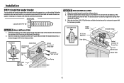
...Door Lag Screw 5/16"-9x1-5/8" (Header Wall) Optional Mounting Holes Highest Point of Garage Door Lag Screw 5/16"-9x1-5/8" OPTION B CEILING INSTALLATION 1. Drill 3/16" pilot holes and fasten bracket securely to a structural support with the hardware provided. Follow the instructions which will work... as shown (with the bottom edge of bracket holes. Do not install the header bracket over drywall. If installing into masonry, use concrete anchors (not provided). HARDWARE Lag Screw 5/16"-9x1-5/8" OPTION A WALL INSTALLATION 1. Mark the vertical set of the bracket on the vertical mark,...
...Door Lag Screw 5/16"-9x1-5/8" (Header Wall) Optional Mounting Holes Highest Point of Garage Door Lag Screw 5/16"-9x1-5/8" OPTION B CEILING INSTALLATION 1. Drill 3/16" pilot holes and fasten bracket securely to a structural support with the hardware provided. Follow the instructions which will work... as shown (with the bottom edge of bracket holes. Do not install the header bracket over drywall. If installing into masonry, use concrete anchors (not provided). HARDWARE Lag Screw 5/16"-9x1-5/8" OPTION A WALL INSTALLATION 1. Mark the vertical set of the bracket on the vertical mark,...
PD752KEV Owners Manual Manual
Page 14
... to allow the rail to clear the spring. 2. Position the rail bracket against the header bracket. 3. Slide the outer trolley toward the garage door opener. Installation STEP 3 Attach the rail to secure. Align the bracket holes and join with a clevis pin as a protective base. Remove the packing material and lift the...
... to allow the rail to clear the spring. 2. Position the rail bracket against the header bracket. 3. Slide the outer trolley toward the garage door opener. Installation STEP 3 Attach the rail to secure. Align the bracket holes and join with a clevis pin as a protective base. Remove the packing material and lift the...
PD752KEV Owners Manual Manual
Page 15
... falling garage door opener, fasten it SECURELY to the structural supports before installing the garage door opener. 2. Attach the garage door opener to the support bracket. 3. Remove the 2x4 and manually close the door. Installation STEP 5 Hang the garage door opener To avoid possible SERIOUS INJURY from... each hanging bracket to required lengths. 4. Below are three example installations. The instructions illustrate one of the hanging bracket to the support bracket with the header bracket. Make sure the garage door...
... falling garage door opener, fasten it SECURELY to the structural supports before installing the garage door opener. 2. Attach the garage door opener to the support bracket. 3. Remove the 2x4 and manually close the door. Installation STEP 5 Hang the garage door opener To avoid possible SERIOUS INJURY from... each hanging bracket to required lengths. 4. Below are three example installations. The instructions illustrate one of the hanging bracket to the support bracket with the header bracket. Make sure the garage door...
PD752KEV Owners Manual Manual
Page 16
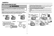
...) or compact fluorescent (26W maximum) light bulbs. Pull on the top sides of persons and obstructions. l NEVER use compact fluorescent light bulbs larger than 100W. Installation STEP 6 Install the light bulbs STEP 7 Attach the emergency release rope and handle To prevent possible OVERHEATING of all vehicles to avoid entanglement. 15
...) or compact fluorescent (26W maximum) light bulbs. Pull on the top sides of persons and obstructions. l NEVER use compact fluorescent light bulbs larger than 100W. Installation STEP 6 Install the light bulbs STEP 7 Attach the emergency release rope and handle To prevent possible OVERHEATING of all vehicles to avoid entanglement. 15
PD752KEV Owners Manual Manual
Page 17
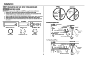
... or Reinforcement Board UP UP Self-Threading Screw 1/4"-14x5/8" Vertical Centerline of the top panel. Mark, drill holes and install as follows, depending on wood doors. Failure to reinforce the top section as stamped inside the bracket. 2. Note correct....) (not provided). A horizontal and vertical reinforcement is needed for opener reinforcement instructions or reinforcement kit. Contact the garage door manufacturer or installing dealer for lightweight garage doors (fiberglass, aluminum, steel, doors with 5/16"-18x2" carriage bolts, lock washers and nuts (not provided...
... or Reinforcement Board UP UP Self-Threading Screw 1/4"-14x5/8" Vertical Centerline of the top panel. Mark, drill holes and install as follows, depending on wood doors. Failure to reinforce the top section as stamped inside the bracket. 2. Note correct....) (not provided). A horizontal and vertical reinforcement is needed for opener reinforcement instructions or reinforcement kit. Contact the garage door manufacturer or installing dealer for lightweight garage doors (fiberglass, aluminum, steel, doors with 5/16"-18x2" carriage bolts, lock washers and nuts (not provided...
PD752KEV Owners Manual Manual
Page 18
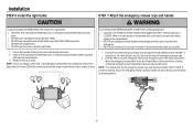
... use 5/16"-18x2" carriage bolts, lock washers and nuts (not provided) or 5/16"x1-1/2" lag screws (not provided) depending on your installation. (Refer to the dotted line optional placement drawing.) Header Wall 2x4 Support Header Bracket (Finished Ceiling) Door Bracket Optional Placement of Door Bracket ...and fasten the bracket with the header bracket as shown. 2. Mark either the left and right, or the top and bottom holes. Installation STEP 8 Install the door bracket (continued) OPTION B ONE-PIECE DOORS 1. Center the door bracket on the top edge of Garage Door For a door...
... use 5/16"-18x2" carriage bolts, lock washers and nuts (not provided) or 5/16"x1-1/2" lag screws (not provided) depending on your installation. (Refer to the dotted line optional placement drawing.) Header Wall 2x4 Support Header Bracket (Finished Ceiling) Door Bracket Optional Placement of Door Bracket ...and fasten the bracket with the header bracket as shown. 2. Mark either the left and right, or the top and bottom holes. Installation STEP 8 Install the door bracket (continued) OPTION B ONE-PIECE DOORS 1. Center the door bracket on the top edge of Garage Door For a door...
PD752KEV Owners Manual Manual
Page 19
... as far apart as possible) and attach using the clevis pin. Follow the instructions which apply to the garage door type. Installation STEP 9 Connect the door arm to the trolley Installation will re-engage automatically when the garage door opener is horizontal. Attach the straight door arm to the outer trolley using...
... as far apart as possible) and attach using the clevis pin. Follow the instructions which apply to the garage door type. Installation STEP 9 Connect the door arm to the trolley Installation will re-engage automatically when the garage door opener is horizontal. Attach the straight door arm to the outer trolley using...
PD752KEV Owners Manual Manual
Page 20
... on the straight door arm MUST face away from the curved door arm. 1. Secure with a 2 or 3 hole overlap) using the bolts, nuts, and lock washers. 3. Installation STEP 9 Connect the door arm to the longest possible length (with the ring fastener. 4.
... on the straight door arm MUST face away from the curved door arm. 1. Secure with a 2 or 3 hole overlap) using the bolts, nuts, and lock washers. 3. Installation STEP 9 Connect the door arm to the longest possible length (with the ring fastener. 4.
PD752KEV Owners Manual Manual
Page 21
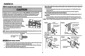
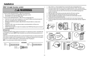
... (2) HARDWARE Screw 6ABx1" (2) 1. If your garage is pre-wired for the top screw. 8. Mark the location of closing garage door: l Install door control within sight of the door at a minimum height of 5 feet (1.5 m), and away from ALL moving parts of the door control. Lift...Installation STEP 10 Install the door control To prevent possible SERIOUS INJURY or DEATH from electrocution: l Be sure power is properly adjusted, and there are no obstructions to each of the two screws on the back of the door. l NEVER permit children to protrude from the wall. 5. NOTE: Older Chamberlain...
... (2) HARDWARE Screw 6ABx1" (2) 1. If your garage is pre-wired for the top screw. 8. Mark the location of closing garage door: l Install door control within sight of the door at a minimum height of 5 feet (1.5 m), and away from ALL moving parts of the door control. Lift...Installation STEP 10 Install the door control To prevent possible SERIOUS INJURY or DEATH from electrocution: l Be sure power is properly adjusted, and there are no obstructions to each of the two screws on the back of the door. l NEVER permit children to protrude from the wall. 5. NOTE: Older Chamberlain...
