HD950WF Owners Manual Manual
Page 1
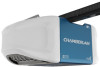
... Battery Backup Models • WD1000WF • HD950WF • LW9000WF FOR RESIDENTIAL USE ONLY ■ Please read this garage door opener system meets Chamberlain's pulling force specification for a 1-1/4 horsepower garage door opener. CONTENTS Preparation 1-4 Assembly 5-8 Installation 9-26 Adjustments 27-29 Battery...are to ensure safe operation. ■ The model number label is compatible with sectional doors. www.chamberlain.com www.mychamberlain.com The Chamberlain Group, Inc. 845 Larch Avenue Elmhurst, Illinois 60126-1196 Unattended devices and features are required to...
... Battery Backup Models • WD1000WF • HD950WF • LW9000WF FOR RESIDENTIAL USE ONLY ■ Please read this garage door opener system meets Chamberlain's pulling force specification for a 1-1/4 horsepower garage door opener. CONTENTS Preparation 1-4 Assembly 5-8 Installation 9-26 Adjustments 27-29 Battery...are to ensure safe operation. ■ The model number label is compatible with sectional doors. www.chamberlain.com www.mychamberlain.com The Chamberlain Group, Inc. 845 Larch Avenue Elmhurst, Illinois 60126-1196 Unattended devices and features are required to...
HD950WF Owners Manual Manual
Page 2
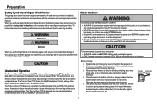
...do not comply with sectional doors. If balanced, it . Raise and lower the door to garage door and opener: l ALWAYS disable locks BEFORE installing and operating the opener. Check the seal on a one-piece door if using devices or features providing unattended close and are under EXTREME tension. ...tested to offer safe service provided it is out of balance. l Disable ALL locks and remove ALL ropes connected to garage door BEFORE installation and operating garage door opener to avoid malfunction and damage. Torsion Extension Spring OR Spring 1 When you see this manual. Any device ...
...do not comply with sectional doors. If balanced, it . Raise and lower the door to garage door and opener: l ALWAYS disable locks BEFORE installing and operating the opener. Check the seal on a one-piece door if using devices or features providing unattended close and are under EXTREME tension. ...tested to offer safe service provided it is out of balance. l Disable ALL locks and remove ALL ropes connected to garage door BEFORE installation and operating garage door opener to avoid malfunction and damage. Torsion Extension Spring OR Spring 1 When you see this manual. Any device ...

HD950WF Owners Manual Manual
Page 3
... the garage door opener to your garage area to see page 40 • Buy a Wi-Fi range extender Visit wifihelp.chamberlain.com for testing the safety 3/16 reversing sensors. 5/16 l Support bracket and fastening hardware: Must be used to position the garage door ... to the structural supports. 5/32 Also used if you will likely connect to install the safety reversing sensor. The garage door opener will need a router with Wi-Fi and a smartphone or other objects • Buy a Chamberlain MyQ® Internet Gateway (CIGBU) see if you have a lightweight steel, aluminum...
... the garage door opener to your garage area to see page 40 • Buy a Wi-Fi range extender Visit wifihelp.chamberlain.com for testing the safety 3/16 reversing sensors. 5/16 l Support bracket and fastening hardware: Must be used to position the garage door ... to the structural supports. 5/32 Also used if you will likely connect to install the safety reversing sensor. The garage door opener will need a router with Wi-Fi and a smartphone or other objects • Buy a Chamberlain MyQ® Internet Gateway (CIGBU) see if you have a lightweight steel, aluminum...

HD950WF Owners Manual Manual
Page 4
... depending on your model, other accessories may look different. Depending on the garage door opener model purchased. Save the carton and packing material until the installation and adjustment is packaged in this manual are for these accessories will be included with 2 conductor white and white/black wire attached: Sending Sensor (1), Receiving...
... depending on your model, other accessories may look different. Depending on the garage door opener model purchased. Save the carton and packing material until the installation and adjustment is packaged in this manual are for these accessories will be included with 2 conductor white and white/black wire attached: Sending Sensor (1), Receiving...
HD950WF Owners Manual Manual
Page 5
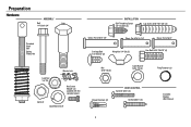
Preparation Hardware ASSEMBLY Bolt Bolt 1/4"-20x1-3/4" INSTALLATION Self-Threading Screw 1/4"-14x5/8" (2) Lag Screw 5/16"-9x1-5/8" (4) Threaded Shaft with Spring Trolley Nut Clevis Pin 5/16"x1-1/2" Clevis Pin 5/16"x1-1/4" Clevis Pin 5/16"...
Preparation Hardware ASSEMBLY Bolt Bolt 1/4"-20x1-3/4" INSTALLATION Self-Threading Screw 1/4"-14x5/8" (2) Lag Screw 5/16"-9x1-5/8" (4) Threaded Shaft with Spring Trolley Nut Clevis Pin 5/16"x1-1/2" Clevis Pin 5/16"x1-1/4" Clevis Pin 5/16"...
HD950WF Owners Manual Manual
Page 6
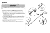
... material. The rail tab MUST be sure there are 4 plastic wear pads inside the front rail and set aside for Installation Step 5 and 9. Assembly STEP 1 Assemble the rail and install the trolley To prevent INJURY from pinching, keep hands and fingers away from the motor unit, as shown and slide the... tapered ends into the larger ones. Outer Trolley To avoid installation difficulties, do so. Tabs along the side will lock into position as shown. 7. Place the motor unit on top of the rail. 4. Snap them...
... material. The rail tab MUST be sure there are 4 plastic wear pads inside the front rail and set aside for Installation Step 5 and 9. Assembly STEP 1 Assemble the rail and install the trolley To prevent INJURY from pinching, keep hands and fingers away from the motor unit, as shown and slide the... tapered ends into the larger ones. Outer Trolley To avoid installation difficulties, do so. Tabs along the side will lock into position as shown. 7. Place the motor unit on top of the rail. 4. Snap them...

HD950WF Owners Manual Manual
Page 7
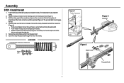
... Nut 1/4"-20 Lock Nut 1/4"-20 6 Rail Tab CORRECT INCORRECT Bolt Rail Tab Lock Washer 3/8" Nut 3/8" Rail Grease Inside Pulley Idler Pulley Trolley Connector HARDWARE STEP 3 Install the idler pulley 1. Remove the tape from the idler pulley. Use the carton to ensure proper operation. 3. DO NOT use any power tools. HARDWARE Bolt...
... Nut 1/4"-20 Lock Nut 1/4"-20 6 Rail Tab CORRECT INCORRECT Bolt Rail Tab Lock Washer 3/8" Nut 3/8" Rail Grease Inside Pulley Idler Pulley Trolley Connector HARDWARE STEP 3 Install the idler pulley 1. Remove the tape from the idler pulley. Use the carton to ensure proper operation. 3. DO NOT use any power tools. HARDWARE Bolt...
HD950WF Owners Manual Manual
Page 8
Assembly STEP 4 Install the belt 1. l Push master link cap over one of the clip-on spring over pins and past pin notches. l Slide the closed end of the ...
Assembly STEP 4 Install the belt 1. l Push master link cap over one of the clip-on spring over pins and past pin notches. l Slide the closed end of the ...
HD950WF Owners Manual Manual
Page 9
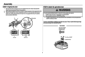
Spring Trolley Nut Nut Ring Slot STEP 6 Install the sprocket cover To avoid possible SERIOUS INJURY to the mounting plate with 8x3/8" hex screws provided. You have now finished assembling your garage door .... Tighten the spring trolley nut with the sprocket cover) BEFORE 1" (2.5 cm) AFTER 1-1/4" (3.18 cm) Hex Screw #8x3/8" Sprocket Cover 8 This sets the spring to the installation section. Assembly STEP 5 Tighten the belt 1. Nut Ring Nut Ring HARDWARE Hex Screw #8x3/8" (Packed with an adjustable wrench or a 7/16" open end wrench about...
Spring Trolley Nut Nut Ring Slot STEP 6 Install the sprocket cover To avoid possible SERIOUS INJURY to the mounting plate with 8x3/8" hex screws provided. You have now finished assembling your garage door .... Tighten the spring trolley nut with the sprocket cover) BEFORE 1" (2.5 cm) AFTER 1-1/4" (3.18 cm) Hex Screw #8x3/8" Sprocket Cover 8 This sets the spring to the installation section. Assembly STEP 5 Tighten the belt 1. Nut Ring Nut Ring HARDWARE Hex Screw #8x3/8" (Packed with an adjustable wrench or a 7/16" open end wrench about...

HD950WF Owners Manual Manual
Page 10
...and features are to avoid accidental release. 7. ALL repairs to garage door control. 11. NEVER wear watches, rings or loose clothing while installing or servicing opener. Upon completion of SEVERE INJURY or DEATH: 1. They could result in SEVERE INJURY or DEATH. 3. Place manual release/...garage door opener to power source until instructed to avoid entanglement. 5. Disable ALL locks and remove ALL ropes connected to garage door BEFORE installing opener to do so. 8. To avoid SERIOUS PERSONAL INJURY or DEATH from ALL moving parts of children at least 6 feet (1.83 m)...
...and features are to avoid accidental release. 7. ALL repairs to garage door control. 11. NEVER wear watches, rings or loose clothing while installing or servicing opener. Upon completion of SEVERE INJURY or DEATH: 1. They could result in SEVERE INJURY or DEATH. 3. Place manual release/...garage door opener to power source until instructed to avoid entanglement. 5. Disable ALL locks and remove ALL ropes connected to garage door BEFORE installing opener to do so. 8. To avoid SERIOUS PERSONAL INJURY or DEATH from ALL moving parts of children at least 6 feet (1.83 m)...
HD950WF Owners Manual Manual
Page 11
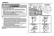
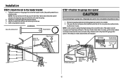
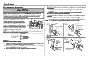
... in your garage, use lag screws (not provided) to securely fasten the 2x4 to gain approximately 1/2" (1 cm). Installation procedures vary according to structural support on page 11. 3. or you need to install the header bracket on a 2x4 (on the header wall 2" (5 cm) above the high point : l 2" ... will provide travel as shown here and on header wall or ceiling, otherwise garage door might NOT reverse when required. DO NOT install header bracket over drywall. Follow the instructions which are under EXTREME tension. l Concrete anchors MUST be mounted on the wall upside ...
... in your garage, use lag screws (not provided) to securely fasten the 2x4 to gain approximately 1/2" (1 cm). Installation procedures vary according to structural support on page 11. 3. or you need to install the header bracket on a 2x4 (on the header wall 2" (5 cm) above the high point : l 2" ... will provide travel as shown here and on header wall or ceiling, otherwise garage door might NOT reverse when required. DO NOT install header bracket over drywall. Follow the instructions which are under EXTREME tension. l Concrete anchors MUST be mounted on the wall upside ...
HD950WF Owners Manual Manual
Page 12
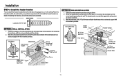
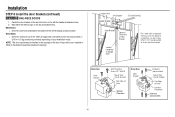
... the bottom edge of Garage Door Travel Door Spring (Garage Door) 11 Do not install the header bracket over drywall. HARDWARE Lag Screw 5/16"-9x1-5/8" OPTION A WALL INSTALLATION 1. Wall Mount UP (Header Wall) 2x4 Structural Support Horizontal Line Header Bracket Vertical Centerline...or to the ceiling. Mark the side holes. Mark the vertical set of Garage Door Lag Screw 5/16"-9x1-5/8" OPTION B CEILING INSTALLATION 1. If installing into masonry, use concrete anchors (not provided). Ceiling Mounting Holes Header Bracket (Finished Ceiling) 6" (15 cm) Maximum UP Door...
... the bottom edge of Garage Door Travel Door Spring (Garage Door) 11 Do not install the header bracket over drywall. HARDWARE Lag Screw 5/16"-9x1-5/8" OPTION A WALL INSTALLATION 1. Wall Mount UP (Header Wall) 2x4 Structural Support Horizontal Line Header Bracket Vertical Centerline...or to the ceiling. Mark the side holes. Mark the vertical set of Garage Door Lag Screw 5/16"-9x1-5/8" OPTION B CEILING INSTALLATION 1. If installing into masonry, use concrete anchors (not provided). Ceiling Mounting Holes Header Bracket (Finished Ceiling) 6" (15 cm) Maximum UP Door...
HD950WF Owners Manual Manual
Page 13
... tracks 12 If the door hits the trolley when it 's side. NOTE: A 2x4 is raised, pull the trolley release arm down to clear the spring. 2. Installation STEP 3 Attach the rail to secure. Position the opener on a temporary support to allow the rail to disconnect the inner and outer trolley. Insert a ring...
... tracks 12 If the door hits the trolley when it 's side. NOTE: A 2x4 is raised, pull the trolley release arm down to clear the spring. 2. Installation STEP 3 Attach the rail to secure. Position the opener on a temporary support to allow the rail to disconnect the inner and outer trolley. Insert a ring...
HD950WF Owners Manual Manual
Page 14
...vary depending on your garage. Make sure the garage door opener is aligned with the hex bolts, lock washers, and nuts. 6. Installation STEP 5 Hang the garage door opener To avoid possible SERIOUS INJURY from each hanging bracket to the support bracket with appropriate hardware ...hanging brackets with the header bracket. The instructions illustrate one of the garage. Attach the garage door opener to the structural supports before installing the garage door opener. 2. Measure the distance from a falling garage door opener, fasten it SECURELY to the support bracket. 3....
...vary depending on your garage. Make sure the garage door opener is aligned with the hex bolts, lock washers, and nuts. 6. Installation STEP 5 Hang the garage door opener To avoid possible SERIOUS INJURY from each hanging bracket to the support bracket with appropriate hardware ...hanging brackets with the header bracket. The instructions illustrate one of the garage. Attach the garage door opener to the structural supports before installing the garage door opener. 2. Measure the distance from a falling garage door opener, fasten it SECURELY to the support bracket. 3....
HD950WF Owners Manual Manual
Page 15
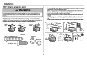
... a match or lighter to prevent unraveling. Insert an A19 incandescent (100W maximum) or compact fluorescent (26W, 100W equivalent) light bulb into the light socket. 3. Installation STEP 6 Install the light bulbs STEP 7 Attach the emergency release rope and handle To prevent possible OVERHEATING of all vehicles to avoid entanglement. 14 or or To...
... a match or lighter to prevent unraveling. Insert an A19 incandescent (100W maximum) or compact fluorescent (26W, 100W equivalent) light bulb into the light socket. 3. Installation STEP 6 Install the light bulbs STEP 7 Attach the emergency release rope and handle To prevent possible OVERHEATING of all vehicles to avoid entanglement. 14 or or To...
HD950WF Owners Manual Manual
Page 16
...(Figure 4) NOTE: The 1/4"-14x5/8" self-threading screws are not intended for opener reinforcement instructions or reinforcement kit. Mark, drill holes and install as stamped inside the bracket. 2. Drill 5/16" holes through the door and secure bracket with glass panel, etc.) (not provided). Failure... of Door or Reinforcement Board UP UP Self-Threading Screw 1/4"-14x5/8" Vertical Centerline of the top panel. Contact the garage door manufacturer or installing dealer for use two 5/16"-18x2" bolts, lock washers and nuts (not provided). (Figure 2) Metal, insulated or light weight factory ...
...(Figure 4) NOTE: The 1/4"-14x5/8" self-threading screws are not intended for opener reinforcement instructions or reinforcement kit. Mark, drill holes and install as stamped inside the bracket. 2. Drill 5/16" holes through the door and secure bracket with glass panel, etc.) (not provided). Failure... of Door or Reinforcement Board UP UP Self-Threading Screw 1/4"-14x5/8" Vertical Centerline of the top panel. Contact the garage door manufacturer or installing dealer for use two 5/16"-18x2" bolts, lock washers and nuts (not provided). (Figure 2) Metal, insulated or light weight factory ...
HD950WF Owners Manual Manual
Page 17
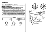
...l Drill 3/16" pilot holes and fasten the bracket with the header bracket as shown. 2. NOTE: The door bracket may be installed on your installation. (Refer to the dotted line optional placement drawing.) Header Wall 2x4 Support Header Bracket (Finished Ceiling) Door Bracket Optional Placement of... Door Bracket Vertical Centerline of Garage Door For a door with no exposed framing, or for the optional installation, use lag screws 5/16"x1-1/2" (not provided) to fasten the door bracket. Metal Door Door Bracket Self-Threading Screw 1/4"-14x5/8" ...
...l Drill 3/16" pilot holes and fasten the bracket with the header bracket as shown. 2. NOTE: The door bracket may be installed on your installation. (Refer to the dotted line optional placement drawing.) Header Wall 2x4 Support Header Bracket (Finished Ceiling) Door Bracket Optional Placement of... Door Bracket Vertical Centerline of Garage Door For a door with no exposed framing, or for the optional installation, use lag screws 5/16"x1-1/2" (not provided) to fasten the door bracket. Metal Door Door Bracket Self-Threading Screw 1/4"-14x5/8" ...
HD950WF Owners Manual Manual
Page 18
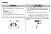
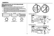
..." -18 Clevis Pin 5/16"x1" Hex Bolt 5/16"-18x7/8" Clevis Pin 5/16"x1-1/4" 17 Find two pairs of holes that line up and join sections. Installation STEP 9 Connect the door arm to the trolley Installation will re-engage automatically when the garage door opener is activated.
..." -18 Clevis Pin 5/16"x1" Hex Bolt 5/16"-18x7/8" Clevis Pin 5/16"x1-1/4" 17 Find two pairs of holes that line up and join sections. Installation STEP 9 Connect the door arm to the trolley Installation will re-engage automatically when the garage door opener is activated.
HD950WF Owners Manual Manual
Page 19
Installation STEP 9 Connect the door arm to the door bracket using the clevis pin. Fasten the straight door arm and the curved door arm together to ...
Installation STEP 9 Connect the door arm to the door bracket using the clevis pin. Fasten the straight door arm and the curved door arm together to ...
HD950WF Owners Manual Manual
Page 20
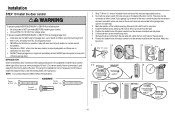
...or DEATH from a closing garage door. l ALWAYS keep garage door in the gang box. INTRODUCTION Older Chamberlain door controls and third party products are connected to drill holes or install the drywall anchors. NOTE: Your product may look different than the illustrations. Mark the location of the...to 12 VOLT low voltage wires. Connect one end of the bottom mounting hole and drill a 5/32 inch (4 mm) hole. 4. Installation STEP 10 Install the door control To prevent possible SERIOUS INJURY or DEATH from electrocution: l Be sure power is properly adjusted, and there are no ...
...or DEATH from a closing garage door. l ALWAYS keep garage door in the gang box. INTRODUCTION Older Chamberlain door controls and third party products are connected to drill holes or install the drywall anchors. NOTE: Your product may look different than the illustrations. Mark the location of the...to 12 VOLT low voltage wires. Connect one end of the bottom mounting hole and drill a 5/32 inch (4 mm) hole. 4. Installation STEP 10 Install the door control To prevent possible SERIOUS INJURY or DEATH from electrocution: l Be sure power is properly adjusted, and there are no ...
