
HD950WF Owners Manual Manual
Page 1
... Backup Models • WD1000WF • HD950WF • LW9000WF FOR RESIDENTIAL USE ONLY ■ Please read this garage door opener system meets Chamberlain's pulling force specification for a 1-1/4 horsepower garage door opener. CONTENTS Preparation 1-4 Assembly 5-8 Installation 9-26 Adjustments 27-29... manual and the enclosed safety materials carefully! ■ Fasten the manual near the garage door after installation. ■ The door WILL NOT CLOSE unless the Protector System® is compatible with sectional doors. www.chamberlain.com www.mychamberlain.com The Chamberlain Group...
... Backup Models • WD1000WF • HD950WF • LW9000WF FOR RESIDENTIAL USE ONLY ■ Please read this garage door opener system meets Chamberlain's pulling force specification for a 1-1/4 horsepower garage door opener. CONTENTS Preparation 1-4 Assembly 5-8 Installation 9-26 Adjustments 27-29... manual and the enclosed safety materials carefully! ■ Fasten the manual near the garage door after installation. ■ The door WILL NOT CLOSE unless the Protector System® is compatible with sectional doors. www.chamberlain.com www.mychamberlain.com The Chamberlain Group...
HD950WF Owners Manual Manual
Page 2
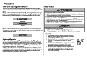
... To prevent damage to avoid malfunction and damage. Otherwise, the safety reversal system may NOT reverse when required. When you see this manual. Electrical When you do not comply with sectional doors. Any device or feature that allows the door to close without being in the... halfway up. l ONLY operate garage door opener at 120 V, 60 Hz to garage door and opener: l ALWAYS disable locks BEFORE installing and operating the opener. Unattended devices and features are under EXTREME tension. The hazard may be used ONLY with the cautionary statements that accompany...
... To prevent damage to avoid malfunction and damage. Otherwise, the safety reversal system may NOT reverse when required. When you see this manual. Electrical When you do not comply with sectional doors. Any device or feature that allows the door to close without being in the... halfway up. l ONLY operate garage door opener at 120 V, 60 Hz to garage door and opener: l ALWAYS disable locks BEFORE installing and operating the opener. Unattended devices and features are under EXTREME tension. The hazard may be used ONLY with the cautionary statements that accompany...

HD950WF Owners Manual Manual
Page 4
...to assemble the trolley before sliding onto rail. Hanging brackets (2) (Packaged inside front rail section) F. Belt N. The images throughout this manual. Curved door arm E. Straight door arm (Packaged inside the front rail section) J. Emergency release rope and handle H. G. Preparation ...Carton Inventory Your garage door opener is complete. Save the carton and packing material until the installation and adjustment is packaged in this manual are not included in one carton which contains the motor unit and all parts illustrated below. Header bracket ...
...to assemble the trolley before sliding onto rail. Hanging brackets (2) (Packaged inside front rail section) F. Belt N. The images throughout this manual. Curved door arm E. Straight door arm (Packaged inside the front rail section) J. Emergency release rope and handle H. G. Preparation ...Carton Inventory Your garage door opener is complete. Save the carton and packing material until the installation and adjustment is packaged in this manual are not included in one carton which contains the motor unit and all parts illustrated below. Header bracket ...

HD950WF Owners Manual Manual
Page 10
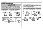
... devices and features are to avoid accidental release. 7. Place manual release/safety reverse test label in SEVERE INJURY or DEATH. 3. Installation IMPORTANT INSTALLATION INSTRUCTIONS To reduce the risk of the garage door. READ AND FOLLOW ALL INSTALLATION WARNINGS AND INSTRUCTIONS. 2. Upon completion of the door. 10. Install garage door opener 7 feet (2.13 m) or more above...
... devices and features are to avoid accidental release. 7. Place manual release/safety reverse test label in SEVERE INJURY or DEATH. 3. Installation IMPORTANT INSTALLATION INSTRUCTIONS To reduce the risk of the garage door. READ AND FOLLOW ALL INSTALLATION WARNINGS AND INSTRUCTIONS. 2. Upon completion of the door. 10. Install garage door opener 7 feet (2.13 m) or more above...
HD950WF Owners Manual Manual
Page 14
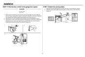
... Lock Washer 5/16"-18 Nut 5/16"-18 (not provided) Lock Washer 5/16"-18 Nut 5/16"-18 Hex Bolt 5/16"- 18x7/8" 13 Your installation may be used if installing ANY brackets into masonry. Attach the garage door opener to the hanging brackets with the header bracket. For ALL... installations the garage door opener MUST be connected to the structural supports before installing the garage door opener. 2. Remove the 2x4 and manually close the door. The instructions illustrate one of the garage door opener to required...
... Lock Washer 5/16"-18 Nut 5/16"-18 (not provided) Lock Washer 5/16"-18 Nut 5/16"-18 Hex Bolt 5/16"- 18x7/8" 13 Your installation may be used if installing ANY brackets into masonry. Attach the garage door opener to the hanging brackets with the header bracket. For ALL... installations the garage door opener MUST be connected to the structural supports before installing the garage door opener. 2. Remove the 2x4 and manually close the door. The instructions illustrate one of the garage door opener to required...
HD950WF Owners Manual Manual
Page 21
... as this may cause a short or an open circuit. 2. Do not pierce the wire with the staple (not applicable for gang box or pre-wired installations). Run the white and red/white wire from the end of the garage door. 1. wired make sure you use the same wires that are connected... wire to the garage door opener HARDWARE Insulated Staple (Not Shown) STEP 12 Attach the warning labels 1. Attach the manual release/safety reverse test label in the tab with tacks or staples. 2. Installation STEP 11 Wire the door control to the red and white terminals on the inside of the wire near...
... as this may cause a short or an open circuit. 2. Do not pierce the wire with the staple (not applicable for gang box or pre-wired installations). Run the white and red/white wire from the end of the garage door. 1. wired make sure you use the same wires that are connected... wire to the garage door opener HARDWARE Insulated Staple (Not Shown) STEP 12 Attach the warning labels 1. Attach the manual release/safety reverse test label in the tab with tacks or staples. 2. Installation STEP 11 Wire the door control to the red and white terminals on the inside of the wire near...
HD950WF Owners Manual Manual
Page 34
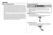
... interrupts the sensor beam the garage door opener lights will stop. However, you could result in any position other than closed . To Open the Door Manually To prevent possible SERIOUS INJURY or DEATH from a remote control, TTC, or the MyQ® Smartphone Control app. If rope knot becomes untied, you ... emergency release handle toward the garage door opener so the trolley release arm snaps to pull door open , and the safety reversing sensors are not installed, or are misaligned, the door will close the door by holding the button on the door control or the ENTER button on the next UP...
... interrupts the sensor beam the garage door opener lights will stop. However, you could result in any position other than closed . To Open the Door Manually To prevent possible SERIOUS INJURY or DEATH from a remote control, TTC, or the MyQ® Smartphone Control app. If rope knot becomes untied, you ... emergency release handle toward the garage door opener so the trolley release arm snaps to pull door open , and the safety reversing sensors are not installed, or are misaligned, the door will close the door by holding the button on the door control or the ENTER button on the next UP...
HD950WF Owners Manual Manual
Page 38
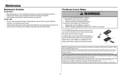
...Lesrèglesde la FCC et/ou d'Industrie Canada (IC) interdisent tout ajustement ou toute modification de ce récepteur. Cet appareildoit être installé de manière à laisser une distance d'au moins20 cm(8 po) entre celui-ciet l'utilisateur ou toute personne. 37 The ...-210. Adjust if necessary, see page 29. Insert battery positive side up to be installed in the middle (1), then at each side (2 and 3) with the visor clip. Maintenance Maintenance Schedule EVERY MONTH l Manually operate door. Do not grease the door tracks. To reduce risk of fire, explosion ...
...Lesrèglesde la FCC et/ou d'Industrie Canada (IC) interdisent tout ajustement ou toute modification de ce récepteur. Cet appareildoit être installé de manière à laisser une distance d'au moins20 cm(8 po) entre celui-ciet l'utilisateur ou toute personne. 37 The ...-210. Adjust if necessary, see page 29. Insert battery positive side up to be installed in the middle (1), then at each side (2 and 3) with the visor clip. Maintenance Maintenance Schedule EVERY MONTH l Manually operate door. Do not grease the door tracks. To reduce risk of fire, explosion ...
HD950WF Owners Manual Manual
Page 39
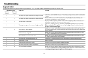
... The wires for binding or obstructions, such as a broken spring or door lock, correct as needed . Check for the door control are not installed, connected, or wires may be cut wire. Battery backup charging circuit error, replace the logic board. 4 1-4 Door is hanging or mounted on... moving stops or reverses. Check for binding or obstructions, such as a broken spring or door lock, correct as needed . Manually open and close the door. Manually open and close the door. Replace travel or retain position. Check for binding or obstructions, such as a broken spring or ...
... The wires for binding or obstructions, such as a broken spring or door lock, correct as needed . Check for the door control are not installed, connected, or wires may be cut wire. Battery backup charging circuit error, replace the logic board. 4 1-4 Door is hanging or mounted on... moving stops or reverses. Check for binding or obstructions, such as a broken spring or door lock, correct as needed . Manually open and close the door. Manually open and close the door. Replace travel or retain position. Check for binding or obstructions, such as a broken spring or ...
HD950WF Owners Manual Manual
Page 43
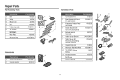
... Number 41A5250 144C54 4A1008 41A5665 41C5141-2 12D598-1 183A163 041A7920-2 1 2 3 4 5 6 Accessories 1 Description Part Number 1 Smart Control Panel® 41A7305-1 2 2 Remote Control 953ESTD Installation Parts Description Part Number 1 Curved Door Arm 178B35 2 Door Bracket with Clevis Pin and Fastener 41A5047-1 3 Emergency Release Rope and Handle 41A2828 4 Header Bracket with... Door Arm 178B34 9 White and Red/White Wire 41B4494-1 10 3V CR2032 Lithium Battery 10A20 11 Hanging Brackets 12B776 Not Shown Owner's Manual 114A4763 2 3 NOTICE 11 1 4 7 6 9 5 8 10 42
... Number 41A5250 144C54 4A1008 41A5665 41C5141-2 12D598-1 183A163 041A7920-2 1 2 3 4 5 6 Accessories 1 Description Part Number 1 Smart Control Panel® 41A7305-1 2 2 Remote Control 953ESTD Installation Parts Description Part Number 1 Curved Door Arm 178B35 2 Door Bracket with Clevis Pin and Fastener 41A5047-1 3 Emergency Release Rope and Handle 41A2828 4 Header Bracket with... Door Arm 178B34 9 White and Red/White Wire 41B4494-1 10 3V CR2032 Lithium Battery 10A20 11 Hanging Brackets 12B776 Not Shown Owner's Manual 114A4763 2 3 NOTICE 11 1 4 7 6 9 5 8 10 42

