
Configuration Guide
Page 7
... DC Power Subsystem 1-42 DC PDU 1-42 DC-Input Power Entry Module 1-44 Power Distribution 1-47 Blower Module 1-47 Air Filters 1-49 Cable-Management System 1-50 Field-Replaceable Units 1-52 Technical Specifications 1-52 Preparing for Installation 2-1 Tools and Equipment 2-2 Safety and Compliance 2-2 General Safety Guidelines 2-3 Cisco 12006 and Cisco 12406 Router Installation and Configuration Guide 5
... DC Power Subsystem 1-42 DC PDU 1-42 DC-Input Power Entry Module 1-44 Power Distribution 1-47 Blower Module 1-47 Air Filters 1-49 Cable-Management System 1-50 Field-Replaceable Units 1-52 Technical Specifications 1-52 Preparing for Installation 2-1 Tools and Equipment 2-2 Safety and Compliance 2-2 General Safety Guidelines 2-3 Cisco 12006 and Cisco 12406 Router Installation and Configuration Guide 5

Configuration Guide
Page 13
...diag Command Reference 5-9 Output Examples 5-14 Maintaining the Router 6-1 Powering Down the Router 6-2 Removing and Installing the Front Door on Cisco 12006 and Cisco 12406 Enhanced Series Router 6-3 Cleaning or Replacing the Air Filters 6-7 Removing and Replacing the Blower Module 6-9 Troubleshooting the Blower Installation 6-12 Removing and Replacing AC and DC Power Subsystem Components 6-... Card 6-48 Installing an RP or Line Card 6-50 Adding an RP or Line Card 6-51 Installing a Line Card Cable-Management Bracket 6-52 Cisco 12006 and Cisco 12406 Router Installation and Configuration Guide 11
...diag Command Reference 5-9 Output Examples 5-14 Maintaining the Router 6-1 Powering Down the Router 6-2 Removing and Installing the Front Door on Cisco 12006 and Cisco 12406 Enhanced Series Router 6-3 Cleaning or Replacing the Air Filters 6-7 Removing and Replacing the Blower Module 6-9 Troubleshooting the Blower Installation 6-12 Removing and Replacing AC and DC Power Subsystem Components 6-... Card 6-48 Installing an RP or Line Card 6-50 Adding an RP or Line Card 6-51 Installing a Line Card Cable-Management Bracket 6-52 Cisco 12006 and Cisco 12406 Router Installation and Configuration Guide 11

Configuration Guide
Page 35
...Alarm Cards, page 1-35 • Power Subsystems, page 1-37 • Blower Module, page 1-47 • Air Filters, page 1-49 • Cable-Management System, page 1-50 Chassis The Cisco 12006 and Cisco 12406 router chassis is an enclosure that consists of the RP, see the "Line Cards" section on page 1-15. ...For more information about the role of the router to five line cards. OL-11497-03 Cisco 12006 and Cisco 12406 Router Installation and Configuration Guide 1-7 For more information about the role of two integral card cages and two power module bays. (...
...Alarm Cards, page 1-35 • Power Subsystems, page 1-37 • Blower Module, page 1-47 • Air Filters, page 1-49 • Cable-Management System, page 1-50 Chassis The Cisco 12006 and Cisco 12406 router chassis is an enclosure that consists of the RP, see the "Line Cards" section on page 1-15. ...For more information about the role of the router to five line cards. OL-11497-03 Cisco 12006 and Cisco 12406 Router Installation and Configuration Guide 1-7 For more information about the role of two integral card cages and two power module bays. (...
Configuration Guide
Page 75
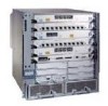
...into +2.5 VDC, +3.3 VDC, +5 VDC, and other equipment vented directly into the router air inlet may result in the card cages. Blower Module Cisco 12006 and Cisco 12406 routers are turned on the chassis. Allow sufficient air flow by maintaining 6 inches (15.24 cm) of clearance at both the inlet and ...-DC converters are equipped with the required power budgets, use the on the side of the chassis, pulls the air through the chassis card cages, and expels it through a connector in the blower module converts -48 VDC into the chassis through two air filters on -line power calculator.
...into +2.5 VDC, +3.3 VDC, +5 VDC, and other equipment vented directly into the router air inlet may result in the card cages. Blower Module Cisco 12006 and Cisco 12406 routers are turned on the chassis. Allow sufficient air flow by maintaining 6 inches (15.24 cm) of clearance at both the inlet and ...-DC converters are equipped with the required power budgets, use the on the side of the chassis, pulls the air through the chassis card cages, and expels it through a connector in the blower module converts -48 VDC into the chassis through two air filters on -line power calculator.
Configuration Guide
Page 76
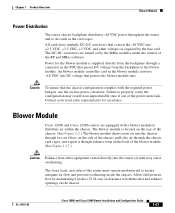
Internal Air Flow (Top View) Air exhaust Air exhaust Blower module Room air Room air 57649 Top view Air filter The two LEDs on the blower module provide a visual indication of three fans within a blower module has failed, it displays a warning message on .... Blower Module Chapter 1 Product Overview Figure 1-17 If the air temperature inside the RP and line card cage rises, the system environmental monitor shuts down to prevent equipment damage from the rear of the chassis. 1-48 Cisco 12006 and Cisco 12406 Router Installation and Configuration Guide OL-11497-03 If the system...
Internal Air Flow (Top View) Air exhaust Air exhaust Blower module Room air Room air 57649 Top view Air filter The two LEDs on the blower module provide a visual indication of three fans within a blower module has failed, it displays a warning message on .... Blower Module Chapter 1 Product Overview Figure 1-17 If the air temperature inside the RP and line card cage rises, the system environmental monitor shuts down to prevent equipment damage from the rear of the chassis. 1-48 Cisco 12006 and Cisco 12406 Router Installation and Configuration Guide OL-11497-03 If the system...
Configuration Guide
Page 77
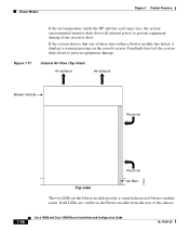
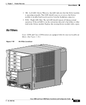
When on , the system has detected a fan failure or other fault in the blower module. Air Filters Cisco 12006 and Cisco 12406 routers are equipped with a spare. Chapter 1 Product Overview Blower Module • OK-Left LED; Red. Green. This LED should... module with two user-serviceable air filters. (See Figure 1-18.) Figure 1-18 Air Filter Locations CISCO 12000 GIGABIT SWITCH SERIES ROUTER EJECT SSLLOOTT--01 RESET AUX CONSOLE COLL RX LINK TX RJ-45 MII GIGABIT ROUTE PROCESSOR 57678 OL-11497-03 Cisco 12006 and Cisco 12406 Router Installation and Configuration Guide ...
When on , the system has detected a fan failure or other fault in the blower module. Air Filters Cisco 12006 and Cisco 12406 routers are equipped with a spare. Chapter 1 Product Overview Blower Module • OK-Left LED; Red. Green. This LED should... module with two user-serviceable air filters. (See Figure 1-18.) Figure 1-18 Air Filter Locations CISCO 12000 GIGABIT SWITCH SERIES ROUTER EJECT SSLLOOTT--01 RESET AUX CONSOLE COLL RX LINK TX RJ-45 MII GIGABIT ROUTE PROCESSOR 57678 OL-11497-03 Cisco 12006 and Cisco 12406 Router Installation and Configuration Guide ...
Configuration Guide
Page 78
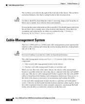
...bending in the "Cleaning or Replacing the Air Filters" section on the right of the front side of the way. The air filters are housed behind a door that is operating. Cable-Management System The Cisco 12006 and Cisco 12406 router cable-management system organizes the interface ... • One line card cable-management bracket on the line card. 1-50 Cisco 12006 and Cisco 12406 Router Installation and Configuration Guide OL-11497-03 Procedures for maintenance and reading the LEDs. Cable-Management System Chapter 1 Product Overview The air filters are located on page 6-7.
...bending in the "Cleaning or Replacing the Air Filters" section on the right of the front side of the way. The air filters are housed behind a door that is operating. Cable-Management System The Cisco 12006 and Cisco 12406 router cable-management system organizes the interface ... • One line card cable-management bracket on the line card. 1-50 Cisco 12006 and Cisco 12406 Router Installation and Configuration Guide OL-11497-03 Procedures for maintenance and reading the LEDs. Cable-Management System Chapter 1 Product Overview The air filters are located on page 6-7.
Configuration Guide
Page 80
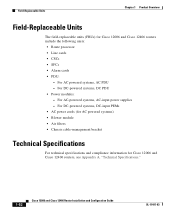
...-powered systems, DC-input PEMs • AC power cords (for AC powered systems) • Blower module • Air filters • Chassis cable-management bracket Technical Specifications For technical specifications and compliance information for Cisco 12006 and Cisco 12406 routers include the following units: • Route processor • Line cards • CSCs • SFCs • Alarm...
...-powered systems, DC-input PEMs • AC power cords (for AC powered systems) • Blower module • Air filters • Chassis cable-management bracket Technical Specifications For technical specifications and compliance information for Cisco 12006 and Cisco 12406 routers include the following units: • Route processor • Line cards • CSCs • SFCs • Alarm...
Configuration Guide
Page 89
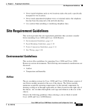
... considerations are discussed: • Airflow • Temperature and humidity Airflow The air circulation system for Cisco 12006 and Cisco 12406 Routers consists of one blower module mounted at the network interface. • Use caution when installing or modifying telephone lines. Air circulates through replaceable air filters located on the right side of the chassis. The blower module...
... considerations are discussed: • Airflow • Temperature and humidity Airflow The air circulation system for Cisco 12006 and Cisco 12406 Routers consists of one blower module mounted at the network interface. • Use caution when installing or modifying telephone lines. Air circulates through replaceable air filters located on the right side of the chassis. The blower module...
Configuration Guide
Page 90
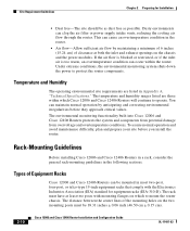
... too warm, an overtemperature condition can clog the air filter or power supply intake vents, reducing the cooling air flow through the router. Under extreme conditions, the environmental monitoring system shuts down the power to operate. The environmental monitoring functionality built into Cisco 12006 and Cisco 12406 Routers protects the system and components from potential damage...
... too warm, an overtemperature condition can clog the air filter or power supply intake vents, reducing the cooling air flow through the router. Under extreme conditions, the environmental monitoring system shuts down the power to operate. The environmental monitoring functionality built into Cisco 12006 and Cisco 12406 Routers protects the system and components from potential damage...

Configuration Guide
Page 93
... Equipment located near the bottom of the rack can assist in the same rack, ensure that there is sufficient ventilation to the air filters and blower module should not be blocked. Ensure that is exhausted from the rear of equipment above, possibly leading to perform equipment... chassis; The blower module is mounted at both the inlet and exhaust openings on the chassis to allow sufficient air flow. • When placing multiple Cisco 12006 and Cisco 12406 Routers in cooling the router. Chapter 2 Preparing for Installation Site Requirement Guidelines Ventilation in an open or in...
... Equipment located near the bottom of the rack can assist in the same rack, ensure that there is sufficient ventilation to the air filters and blower module should not be blocked. Ensure that is exhausted from the rear of equipment above, possibly leading to perform equipment... chassis; The blower module is mounted at both the inlet and exhaust openings on the chassis to allow sufficient air flow. • When placing multiple Cisco 12006 and Cisco 12406 Routers in cooling the router. Chapter 2 Preparing for Installation Site Requirement Guidelines Ventilation in an open or in...
Configuration Guide
Page 106
...the Chassis on a Tabletop or Flat Surface, page 3-9 Before installing Cisco 12006 and Cisco 12406 Routers, see Chapter 2, "Preparing for Installation," for the router. • AC power source receptacles are not blocked. • The air filter is mounted on the equipment have been checked for compatibility with your ... Do not mix power module input types in a router must be either AC-input power supplies or DC-input PEMs. Cisco 12006 and Cisco 12406 Router Installation and Configuration Guide 3-2 OL-11497-03 All power modules installed in the router. Installing a Router Chapter 3 ...
...the Chassis on a Tabletop or Flat Surface, page 3-9 Before installing Cisco 12006 and Cisco 12406 Routers, see Chapter 2, "Preparing for Installation," for the router. • AC power source receptacles are not blocked. • The air filter is mounted on the equipment have been checked for compatibility with your ... Do not mix power module input types in a router must be either AC-input power supplies or DC-input PEMs. Cisco 12006 and Cisco 12406 Router Installation and Configuration Guide 3-2 OL-11497-03 All power modules installed in the router. Installing a Router Chapter 3 ...

Configuration Guide
Page 110
Caution When installing the right side lower center-mount bracket, ensure that the bracket does not impede airflow through the air filter, which could cause overheating in the bracket and finger tighten that aligns with a hole in the rack rail, then insert a ...c. Hold the lower right bracket against the right rack rail and align the bottom screw hole in the hole and finger tighten the screw. Cisco 12006 and Cisco 12406 Router Installation and Configuration Guide 3-6 OL-11497-03 Use a screwdriver to install the optional center-mount rack-mounting brackets: • Number 2...
Caution When installing the right side lower center-mount bracket, ensure that the bracket does not impede airflow through the air filter, which could cause overheating in the bracket and finger tighten that aligns with a hole in the rack rail, then insert a ...c. Hold the lower right bracket against the right rack rail and align the bottom screw hole in the hole and finger tighten the screw. Cisco 12006 and Cisco 12406 Router Installation and Configuration Guide 3-6 OL-11497-03 Use a screwdriver to install the optional center-mount rack-mounting brackets: • Number 2...
Configuration Guide
Page 224
... Queued messages: %ENVM-1-SHUTDOWN: Environmental Monitor initiated shutdown If an environmental shutdown results from an out-of the chassis. If the air filters appear dirty, remove the filters and either vacuum them or replace them. • The preceding message could also indicate a faulty component or temperature sensor. Problem ... is sufficient clearance-at least 6 inches (15.24 cm)- Refer to resolve the problem, contact a service representative for assistance. 4-36 Cisco 12006 and Cisco 12406 Router Installation and Configuration Guide OL-11497-03 Before the system shuts down .
... Queued messages: %ENVM-1-SHUTDOWN: Environmental Monitor initiated shutdown If an environmental shutdown results from an out-of the chassis. If the air filters appear dirty, remove the filters and either vacuum them or replace them. • The preceding message could also indicate a faulty component or temperature sensor. Problem ... is sufficient clearance-at least 6 inches (15.24 cm)- Refer to resolve the problem, contact a service representative for assistance. 4-36 Cisco 12006 and Cisco 12406 Router Installation and Configuration Guide OL-11497-03 Before the system shuts down .
Configuration Guide
Page 245
... Router, page 6-2 • Removing and Installing the Front Door on Cisco 12006 and Cisco 12406 Enhanced Series Router, page 6-3 • Cleaning or Replacing the Air Filters, page 6-7 • Cleaning or Replacing the Air Filters, page 6-7 • Removing and Replacing the Blower Module, page 6-9...Removing and Installing an RP or a Line Card, page 6-47 Cisco 12006 and Cisco 12406 Router Installation and Configuration Guide 6-1 6 C H A P T E R Maintaining the Router OL-11497-03 The Cisco 12006 or Cisco 12406 Router is equipped as your networking requirements change, you might need...
... Router, page 6-2 • Removing and Installing the Front Door on Cisco 12006 and Cisco 12406 Enhanced Series Router, page 6-3 • Cleaning or Replacing the Air Filters, page 6-7 • Cleaning or Replacing the Air Filters, page 6-7 • Removing and Replacing the Blower Module, page 6-9...Removing and Installing an RP or a Line Card, page 6-47 Cisco 12006 and Cisco 12406 Router Installation and Configuration Guide 6-1 6 C H A P T E R Maintaining the Router OL-11497-03 The Cisco 12006 or Cisco 12406 Router is equipped as your networking requirements change, you might need...

Configuration Guide
Page 251
...Align the pivot blocks on the front door with the hinges on the right side of the chassis. c. Cleaning or Replacing the Air Filters The Cisco 12006 and Cisco 12406 routers are equipped with the hinge pins on the right side of the chassis and install the hinge pins to hold the door ...in dusty environments), examine the air filters. OL-11497-03 Cisco 12006 and Cisco 12406 Router Installation and Configuration Guide 6-7 One time per month (or more often in place (see Figure 6-2). Close the front door...
...Align the pivot blocks on the front door with the hinges on the right side of the chassis. c. Cleaning or Replacing the Air Filters The Cisco 12006 and Cisco 12406 routers are equipped with the hinge pins on the right side of the chassis and install the hinge pins to hold the door ...in dusty environments), examine the air filters. OL-11497-03 Cisco 12006 and Cisco 12406 Router Installation and Configuration Guide 6-7 One time per month (or more often in place (see Figure 6-2). Close the front door...

Configuration Guide
Page 252
... GIGABIT ROUTE PROCESSOR 129403 1 Air filter door 2 Air filters Cisco 12006 and Cisco 12406 Router Installation and Configuration Guide 6-8 OL-11497-03 Step 1 Open the spring-loaded air filter door on the right side of the chassis and remove an air filter by pulling the small tab on the edge of the filter (Figure 6-4). Cleaning or Replacing the Air Filters Chapter 6 Maintaining the Router...
... GIGABIT ROUTE PROCESSOR 129403 1 Air filter door 2 Air filters Cisco 12006 and Cisco 12406 Router Installation and Configuration Guide 6-8 OL-11497-03 Step 1 Open the spring-loaded air filter door on the right side of the chassis and remove an air filter by pulling the small tab on the edge of the filter (Figure 6-4). Cleaning or Replacing the Air Filters Chapter 6 Maintaining the Router...

Configuration Guide
Page 253
...module (12000/6-BLOWER=)-Use an enhanced capacity blower module as a replacement. Always install the air filter with Cisco 12006 and Cisco 12406 series routers, airflow capacity for the Cisco 12006 and Cisco 12406 series routers; Removing and Replacing the Blower Module The illustrations in toward the RP and line...the new blower module. Note An arrow located on the edge of each air filter frame that ship with original systems, and enhanced capacity blowers that indicates the direction of air flow. OL-11497-03 Cisco 12006 and Cisco 12406 Router Installation and Configuration Guide 6-9
...module (12000/6-BLOWER=)-Use an enhanced capacity blower module as a replacement. Always install the air filter with Cisco 12006 and Cisco 12406 series routers, airflow capacity for the Cisco 12006 and Cisco 12406 series routers; Removing and Replacing the Blower Module The illustrations in toward the RP and line...the new blower module. Note An arrow located on the edge of each air filter frame that ship with original systems, and enhanced capacity blowers that indicates the direction of air flow. OL-11497-03 Cisco 12006 and Cisco 12406 Router Installation and Configuration Guide 6-9

Configuration Guide
Page 312
... • Vacuum cleaner • Antistatic bag or similar ESD-preventive container • Replacement chassis, Part Number: GSR6/120= 6-68 Cisco 12006 and Cisco 12406 Router Installation and Configuration Guide OL-11497-03 Tools and Equipment You need the following sections. The replacement chassis is an integrated, sheet-...-slot clock and scheduler card cage • Three-slot switch fabric card cage • Two alarm card slots • Two air filters • Two power module bays • One backplane with connectors The chassis can be rack mounted or placed on a stable flat surface.
... • Vacuum cleaner • Antistatic bag or similar ESD-preventive container • Replacement chassis, Part Number: GSR6/120= 6-68 Cisco 12006 and Cisco 12406 Router Installation and Configuration Guide OL-11497-03 Tools and Equipment You need the following sections. The replacement chassis is an integrated, sheet-...-slot clock and scheduler card cage • Three-slot switch fabric card cage • Two alarm card slots • Two air filters • Two power module bays • One backplane with connectors The chassis can be rack mounted or placed on a stable flat surface.
Configuration Guide
Page 313
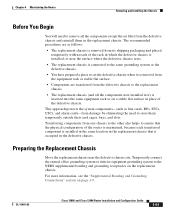
...central office grounding system or interior equipment grounding system to the NEBS supplemental bonding and grounding receptacles on page 3-9. OL-11497-03 Cisco 12006 and Cisco 12406 Router Installation and Configuration Guide 6-69 For more information, see the "Supplemental Bonding and Grounding Connections" section on the replacement chassis.... are transferred from the defective chassis to the replacement chassis. • The replacement chassis (and all the components except the air filter from its shipping packaging and placed temporarily within reach of the defective chassis.
...central office grounding system or interior equipment grounding system to the NEBS supplemental bonding and grounding receptacles on page 3-9. OL-11497-03 Cisco 12006 and Cisco 12406 Router Installation and Configuration Guide 6-69 For more information, see the "Supplemental Bonding and Grounding Connections" section on the replacement chassis.... are transferred from the defective chassis to the replacement chassis. • The replacement chassis (and all the components except the air filter from its shipping packaging and placed temporarily within reach of the defective chassis.
