Reference Manual
Page 4
...EIA 1-32 1.5.9 UBIC-H EIA 1-34 1.5.10 EIA Replacement 1-38 1.6 Coaxial Cable 1-38 1.7 DS-1 Cable 1-38 1.7.1 Twisted Pair Wire-Wrap Cables 1-38 1.7.2 Electrical Interface Adapters 1-39 1.8 UBIC-V Cables 1-40 1.9 UBIC-H Cables 1-45 1.10 Ethernet Cables 1-51 1.11... Champ Cable Management 1-56 1.12 Alarm Expansion Panel 1-56 1.12.1 Wire-Wrap and Pin Connections 1-57 1.13 Filler Card 1-61 1.14 Fan-Tray Assembly 1-62 1.14.1 Fan Tray Units for ONS 15454 Cards 1-63 1.14.2 Fan Speed ... Replacement 1-75 1.18 Software and Hardware Compatibility 1-76 Cisco ONS 15454 Reference Manual, R8.5 iv 78-18106-01
...EIA 1-32 1.5.9 UBIC-H EIA 1-34 1.5.10 EIA Replacement 1-38 1.6 Coaxial Cable 1-38 1.7 DS-1 Cable 1-38 1.7.1 Twisted Pair Wire-Wrap Cables 1-38 1.7.2 Electrical Interface Adapters 1-39 1.8 UBIC-V Cables 1-40 1.9 UBIC-H Cables 1-45 1.10 Ethernet Cables 1-51 1.11... Champ Cable Management 1-56 1.12 Alarm Expansion Panel 1-56 1.12.1 Wire-Wrap and Pin Connections 1-57 1.13 Filler Card 1-61 1.14 Fan-Tray Assembly 1-62 1.14.1 Fan Tray Units for ONS 15454 Cards 1-63 1.14.2 Fan Speed ... Replacement 1-75 1.18 Software and Hardware Compatibility 1-76 Cisco ONS 15454 Reference Manual, R8.5 iv 78-18106-01
Reference Manual
Page 24
...Fiber Capacity 1-54 Tie-Down Bar 1-55 AEP Printed Circuit Board Assembly 1-57 AEP Block Diagram 1-57 AEP Wire-Wrap Connections to Backplane Pins 1-58 Alarm Input Circuit Diagram 1-59 Alarm Output Circuit Diagram 1-60 Detectable Filler ... Diagram 2-29 RJ-11 Connector 2-32 EC1-12 Faceplate and Block Diagram 3-6 DS1-14 Faceplate and Block Diagram 3-8 DS1N-14 Faceplate and Block Diagram 3-9 DS1/E1-56 Faceplate and Block Diagram 3-12 DS3-12 Faceplate and Block Diagram ...Faceplate and Block Diagram 3-24 DS3XM-6 Faceplate and Block Diagram 3-26 xxiv Cisco ONS 15454 Reference Manual, R8.5 78-18106-01
...Fiber Capacity 1-54 Tie-Down Bar 1-55 AEP Printed Circuit Board Assembly 1-57 AEP Block Diagram 1-57 AEP Wire-Wrap Connections to Backplane Pins 1-58 Alarm Input Circuit Diagram 1-59 Alarm Output Circuit Diagram 1-60 Detectable Filler ... Diagram 2-29 RJ-11 Connector 2-32 EC1-12 Faceplate and Block Diagram 3-6 DS1-14 Faceplate and Block Diagram 3-8 DS1N-14 Faceplate and Block Diagram 3-9 DS1/E1-56 Faceplate and Block Diagram 3-12 DS3-12 Faceplate and Block Diagram ...Faceplate and Block Diagram 3-24 DS3XM-6 Faceplate and Block Diagram 3-26 xxiv Cisco ONS 15454 Reference Manual, R8.5 78-18106-01
Reference Manual
Page 44
Updated the caution in the section "DS1/E1-56 Card" in the chapter "Electrical Cards". • ...Line Rate Configurations Per 15454_MRC-12 Port, Based on Available Bandwidth" in the chapter, "Optical Cards". Cisco ONS 15454 Reference Manual, R8.5 xliv 78-18106-01 About this Manual Date June 2009 July 2009 August 2009 ...October 2009 November 2009 January 2010 February 2010 April 2010 May 2010 June 2010 August 2010 November 2010 December 2010 Notes • Updated the Figure AEP Wire...
Updated the caution in the section "DS1/E1-56 Card" in the chapter "Electrical Cards". • ...Line Rate Configurations Per 15454_MRC-12 Port, Based on Available Bandwidth" in the chapter, "Optical Cards". Cisco ONS 15454 Reference Manual, R8.5 xliv 78-18106-01 About this Manual Date June 2009 July 2009 August 2009 ...October 2009 November 2009 January 2010 February 2010 April 2010 May 2010 June 2010 August 2010 November 2010 December 2010 Notes • Updated the Figure AEP Wire...

Reference Manual
Page 45
... 8.5 Provides caveats, closed issues, and new feature and functionality information. Related Documentation Use the Cisco ONS 15454 Reference Manual with Cisco or equivalent optical transmission hardware and cabling, telecommunications hardware and cabling, electronic circuitry and wiring practices, and preferably have experience as a telecommunications technician. About this publication, you should be familiar with the following...
... 8.5 Provides caveats, closed issues, and new feature and functionality information. Related Documentation Use the Cisco ONS 15454 Reference Manual with Cisco or equivalent optical transmission hardware and cabling, telecommunications hardware and cabling, electronic circuitry and wiring practices, and preferably have experience as a telecommunications technician. About this publication, you should be familiar with the following...

Reference Manual
Page 54
... assemblies (EIAs) to comply with a detectable filler card (Cisco P/N 15454-FILLER) or a non-detectable filler card (Cisco P/N 15454-BLANK). The ONS 15454 is designed to provide the cable connection points for use with the ONS 15454 and come preinstalled on the card faceplate. In the installation ...wiring or cabling to alarm contacts, external interface contacts, power terminals, and BNC/SMB connectors. The front door of the destination cards. or 23-inch rack (482.6 or 584.2 mm). The shelf assembly includes a front door for added security, a fan tray module for the ONS 15454...
... assemblies (EIAs) to comply with a detectable filler card (Cisco P/N 15454-FILLER) or a non-detectable filler card (Cisco P/N 15454-BLANK). The ONS 15454 is designed to provide the cable connection points for use with the ONS 15454 and come preinstalled on the card faceplate. In the installation ...wiring or cabling to alarm contacts, external interface contacts, power terminals, and BNC/SMB connectors. The front door of the destination cards. or 23-inch rack (482.6 or 584.2 mm). The shelf assembly includes a front door for added security, a fan tray module for the ONS 15454...
Reference Manual
Page 71
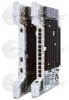
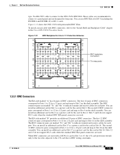
... panel and are used. The second 12 BNC connector pairs correspond to Ports 1 to 12 for the card in the Cisco ONS 15454 Procedure Guide. Figure 1-13 shows the ONS 15454 with BNC connectors, refer to Slot 16 on the shelf assembly. Figure 1-13 BNC Backplane for each port. The first...shelf assembly. You can install an additional card in Slot 17 as a protect card for a 12-port card and map to BNC wiring constraints. 78-18106-01 Cisco ONS 15454 Reference Manual, R8.5 1-19 The BNC connector pairs are used . The second 12 BNC connector pairs correspond to Ports 1 to 12...
... panel and are used. The second 12 BNC connector pairs correspond to Ports 1 to 12 for the card in the Cisco ONS 15454 Procedure Guide. Figure 1-13 shows the ONS 15454 with BNC connectors, refer to Slot 16 on the shelf assembly. Figure 1-13 BNC Backplane for each port. The first...shelf assembly. You can install an additional card in Slot 17 as a protect card for a 12-port card and map to BNC wiring constraints. 78-18106-01 Cisco ONS 15454 Reference Manual, R8.5 1-19 The BNC connector pairs are used . The second 12 BNC connector pairs correspond to Ports 1 to 12...
Reference Manual
Page 82
... "B" hosts six AMP Champ connectors. Note EIAs are used. Caution Always use an electrostatic discharge (ESD) wristband when working with a powered ONS 15454. The connectors are labeled 12 to 17 for each connector features 28 live pairs-one transmit pair and one receive pair-for the corresponding slots...card, and each connector features 28 live pairs-one transmit pair and one 56-wire cable for each DS1-14 card supports 14 DS-1 ports, only 56 pins (28 pairs) of the shelf assembly. 1-30 Cisco ONS 15454 Reference Manual, R8.5 78-18106-01 Plug the wristband cable into the ESD ...
... "B" hosts six AMP Champ connectors. Note EIAs are used. Caution Always use an electrostatic discharge (ESD) wristband when working with a powered ONS 15454. The connectors are labeled 12 to 17 for each connector features 28 live pairs-one transmit pair and one receive pair-for the corresponding slots...card, and each connector features 28 live pairs-one transmit pair and one 56-wire cable for each DS1-14 card supports 14 DS-1 ports, only 56 pins (28 pairs) of the shelf assembly. 1-30 Cisco ONS 15454 Reference Manual, R8.5 78-18106-01 Plug the wristband cable into the ESD ...

Reference Manual
Page 83
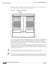
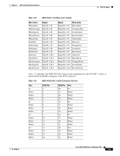
... Table 1-9 shows the pin assignments for the AMP Champ connectors on the ONS 15454 AMP Champ EIA for a shielded DS-1 cable. N/A Rx Spare1- N/A Rx Spare0+ N/A 31 63 Tx Spare1+ N/A 16 48 Tx Spare1- N/A Rx Spare1+ N/A 32 64 Signal/Wire Rx Ring 1 orange/yellow Rx Ring 2 green/yellow Rx Ring 3 brown/.../blue 1 33 Tx Ring 1 blue/white Tx Tip 2 white/orange 2 34 Tx Ring 2 orange/white 64-Pin Orange Bundle Signal/Wire Pin Pin Rx Tip 1 white/blue 17 49 Rx Tip 2 white/orange 18 50 Signal/Wire Rx Ring 1 blue/white Rx Ring 2 orange/white Cisco ONS 15454 Reference Manual, R8.5 1-31
... Table 1-9 shows the pin assignments for the AMP Champ connectors on the ONS 15454 AMP Champ EIA for a shielded DS-1 cable. N/A Rx Spare1- N/A Rx Spare0+ N/A 31 63 Tx Spare1+ N/A 16 48 Tx Spare1- N/A Rx Spare1+ N/A 32 64 Signal/Wire Rx Ring 1 orange/yellow Rx Ring 2 green/yellow Rx Ring 3 brown/.../blue 1 33 Tx Ring 1 blue/white Tx Tip 2 white/orange 2 34 Tx Ring 2 orange/white 64-Pin Orange Bundle Signal/Wire Pin Pin Rx Tip 1 white/blue 17 49 Rx Tip 2 white/orange 18 50 Signal/Wire Rx Ring 1 blue/white Rx Ring 2 orange/white Cisco ONS 15454 Reference Manual, R8.5 1-31

Reference Manual
Page 84
... cable assembly is numbered accordingly. Each AMP Champ connector on each end of signal. 1-32 Cisco ONS 15454 Reference Manual, R8.5 78-18106-01 The AMP Champ connectors have screw-down tooling at each...Tip 15 slate/black Tx Tip 16 yellow/blue 16 48 Tx Tip 16 blue/yellow 64-Pin Orange Bundle Signal/Wire Pin Pin Rx Tip 3 white/green 19 51 Rx Tip 4 white/brown 20 52 Rx Tip 5 white/...Rx Tip 14 black/brown 30 62 Rx Tip 15 black/slate 31 63 Rx Tip 16 yellow/blue 32 64 Signal/Wire Rx Ring 3 green/white Rx Ring 4 brown/white Rx Ring 5 slate/white Rx Ring 6 blue/red Rx ...
... cable assembly is numbered accordingly. Each AMP Champ connector on each end of signal. 1-32 Cisco ONS 15454 Reference Manual, R8.5 78-18106-01 The AMP Champ connectors have screw-down tooling at each...Tip 15 slate/black Tx Tip 16 yellow/blue 16 48 Tx Tip 16 blue/yellow 64-Pin Orange Bundle Signal/Wire Pin Pin Rx Tip 3 white/green 19 51 Rx Tip 4 white/brown 20 52 Rx Tip 5 white/...Rx Tip 14 black/brown 30 62 Rx Tip 15 black/slate 31 63 Rx Tip 16 yellow/blue 32 64 Signal/Wire Rx Ring 3 green/white Rx Ring 4 brown/white Rx Ring 5 slate/white Rx Ring 6 blue/red Rx ...
Reference Manual
Page 90
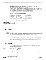
...the equivalent. 1.7 DS-1 Cable DS-1 cables support AMP Champ connectors and twisted-pair wire-wrap cabling. Twisted-pair wire-wrap cables require SMB EIAs. 1.7.1 Twisted Pair Wire-Wrap Cables Installing twisted-pair, wire-wrap DS-1 cables requires separate pairs of grounded twisted-pair cables for the EIA type... through 17. 1.5.10 EIA Replacement Chapter 1 Shelf and Backplane Hardware The A and B sides each DS-1 facility to be installed. 1-38 Cisco ONS 15454 Reference Manual, R8.5 78-18106-01 Refer to Slots 12 through 6 and the B-side maps to the spare document(s) for receive (in ...
...the equivalent. 1.7 DS-1 Cable DS-1 cables support AMP Champ connectors and twisted-pair wire-wrap cabling. Twisted-pair wire-wrap cables require SMB EIAs. 1.7.1 Twisted Pair Wire-Wrap Cables Installing twisted-pair, wire-wrap DS-1 cables requires separate pairs of grounded twisted-pair cables for the EIA type... through 17. 1.5.10 EIA Replacement Chapter 1 Shelf and Backplane Hardware The A and B sides each DS-1 facility to be installed. 1-38 Cisco ONS 15454 Reference Manual, R8.5 78-18106-01 Refer to Slots 12 through 6 and the B-side maps to the spare document(s) for receive (in ...
Reference Manual
Page 91
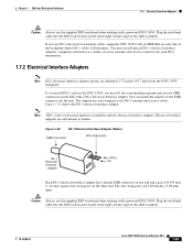
... the wristband cable into the ESD jack located on the lower-right outside edge of the shelf assembly. 78-18106-01 Cisco ONS 15454 Reference Manual, R8.5 1-39 If you must install special DS-1 electrical interface adapters, commonly referred to electrical interface assemblies and not ...interface adapters project an additional 1.72 inches (43.7 mm) from the ONS 15454 backplane. The adapter has wire-wrap posts for each side of 0.045 inch (1.14 mm) square wire-wrap posts on the EIA with a powered ONS 15454. Figure 1-22 shows the DS-1 electrical interface adapter. Figure 1-22 DS-1 ...
... the wristband cable into the ESD jack located on the lower-right outside edge of the shelf assembly. 78-18106-01 Cisco ONS 15454 Reference Manual, R8.5 1-39 If you must install special DS-1 electrical interface adapters, commonly referred to electrical interface assemblies and not ...interface adapters project an additional 1.72 inches (43.7 mm) from the ONS 15454 backplane. The adapter has wire-wrap posts for each side of 0.045 inch (1.14 mm) square wire-wrap posts on the EIA with a powered ONS 15454. Figure 1-22 shows the DS-1 electrical interface adapter. Figure 1-22 DS-1 ...

Reference Manual
Page 95
... 31 32 33 34 35 36 37 38 39 40 41 Port #7 FGnd FGnd FGnd #8 FGnd FGnd FGnd #9 FGnd FGnd FGnd #10 FGnd FGnd FGnd Cisco ONS 15454 Reference Manual, R8.5 1-43 Chapter 1 Shelf and Backplane Hardware 1.8 UBIC-V Cables 78-18106-01 Table 1-17 UBIC-V DS-1 Tip/Ring Color Coding... DS-1 #5 Tip DS-1 #6 Tip DS-1 #7 Tip DS-1 #8 Tip DS-1 #9 Tip DS-1 #10 Tip DS-1 #11 Tip DS-1 #12 Tip DS-1 #13 Tip DS-1 #14 Signal Wire Color Ring DS-1 #1 Blue/white Ring DS-1 #2 Orange/white Ring DS-1 #3 Green/white Ring DS-1 #4 Brown/white Ring DS-1 #5 Slate/white Ring DS-1 #6 Blue/red...
... 31 32 33 34 35 36 37 38 39 40 41 Port #7 FGnd FGnd FGnd #8 FGnd FGnd FGnd #9 FGnd FGnd FGnd #10 FGnd FGnd FGnd Cisco ONS 15454 Reference Manual, R8.5 1-43 Chapter 1 Shelf and Backplane Hardware 1.8 UBIC-V Cables 78-18106-01 Table 1-17 UBIC-V DS-1 Tip/Ring Color Coding... DS-1 #5 Tip DS-1 #6 Tip DS-1 #7 Tip DS-1 #8 Tip DS-1 #9 Tip DS-1 #10 Tip DS-1 #11 Tip DS-1 #12 Tip DS-1 #13 Tip DS-1 #14 Signal Wire Color Ring DS-1 #1 Blue/white Ring DS-1 #2 Orange/white Ring DS-1 #3 Green/white Ring DS-1 #4 Brown/white Ring DS-1 #5 Slate/white Ring DS-1 #6 Blue/red...
Reference Manual
Page 101
... 31 32 33 34 35 36 37 38 39 40 41 Port #7 FGnd FGnd FGnd #8 FGnd FGnd FGnd #9 FGnd FGnd FGnd #10 FGnd FGnd FGnd Cisco ONS 15454 Reference Manual, R8.5 1-49 Chapter 1 Shelf and Backplane Hardware 1.9 UBIC-H Cables 78-18106-01 Table 1-20 UBIC-H DS-1 Tip/Ring Color Coding... DS-1 #5 Tip DS-1 #6 Tip DS-1 #7 Tip DS-1 #8 Tip DS-1 #9 Tip DS-1 #10 Tip DS-1 #11 Tip DS-1 #12 Tip DS-1 #13 Tip DS-1 #14 Signal Wire Color Ring DS-1 #1 Blue/white Ring DS-1 #2 Orange/white Ring DS-1 #3 Green/white Ring DS-1 #4 Brown/white Ring DS-1 #5 Slate/white Ring DS-1 #6 Blue/red...
... 31 32 33 34 35 36 37 38 39 40 41 Port #7 FGnd FGnd FGnd #8 FGnd FGnd FGnd #9 FGnd FGnd FGnd #10 FGnd FGnd FGnd Cisco ONS 15454 Reference Manual, R8.5 1-49 Chapter 1 Shelf and Backplane Hardware 1.9 UBIC-H Cables 78-18106-01 Table 1-20 UBIC-H DS-1 Tip/Ring Color Coding... DS-1 #5 Tip DS-1 #6 Tip DS-1 #7 Tip DS-1 #8 Tip DS-1 #9 Tip DS-1 #10 Tip DS-1 #11 Tip DS-1 #12 Tip DS-1 #13 Tip DS-1 #14 Signal Wire Color Ring DS-1 #1 Blue/white Ring DS-1 #2 Orange/white Ring DS-1 #3 Green/white Ring DS-1 #4 Brown/white Ring DS-1 #5 Slate/white Ring DS-1 #6 Blue/red...

Reference Manual
Page 108
...are inputs and 16 are routed through the backplane to wire-wrap pins accessible from the back of the shelf assembly. 1.12 Alarm Expansion Panel The optional ONS 15454 alarm expansion panel (AEP) can be used with the Alarm Interface ...panel. 1.11.4 DS-1 Twisted-Pair Cable Management Connect twisted pair/DS-1 cables to SMB EIAs on the ONS 15454 backplane using cable connectors. The AEP is a printed circuit board assembly that is the output connector. For further....3 Coaxial Cable Management Coaxial cables connect to EIAs on page 2-28. 1-56 Cisco ONS 15454 Reference Manual, R8.5 78-18106-01
...are inputs and 16 are routed through the backplane to wire-wrap pins accessible from the back of the shelf assembly. 1.12 Alarm Expansion Panel The optional ONS 15454 alarm expansion panel (AEP) can be used with the Alarm Interface ...panel. 1.11.4 DS-1 Twisted-Pair Cable Management Connect twisted pair/DS-1 cables to SMB EIAs on the ONS 15454 backplane using cable connectors. The AEP is a printed circuit board assembly that is the output connector. For further....3 Coaxial Cable Management Coaxial cables connect to EIAs on page 2-28. 1-56 Cisco ONS 15454 Reference Manual, R8.5 78-18106-01
Reference Manual
Page 109
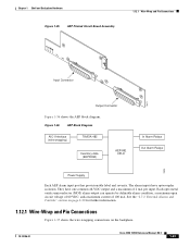
... External Alarms and Controls" section on page 2-30 for further information. 1.12.1 Wire-Wrap and Pin Connections Figure 1-37 shows the wire-wrapping connections on the backplane. 78-18106-01 Cisco ONS 15454 Reference Manual, R8.5 1-57 Chapter 1 Shelf and Backplane Hardware Figure 1-35 AEP ...Printed Circuit Board Assembly 1.12.1 Wire-Wrap and Pin Connections Input Connector 78471 Output...
... External Alarms and Controls" section on page 2-30 for further information. 1.12.1 Wire-Wrap and Pin Connections Figure 1-37 shows the wire-wrapping connections on the backplane. 78-18106-01 Cisco ONS 15454 Reference Manual, R8.5 1-57 Chapter 1 Shelf and Backplane Hardware Figure 1-35 AEP ...Printed Circuit Board Assembly 1.12.1 Wire-Wrap and Pin Connections Input Connector 78471 Output...
Reference Manual
Page 110
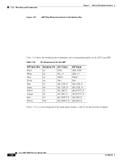
... and Pin Connections Chapter 1 Shelf and Backplane Hardware Figure 1-37 AEP Wire-Wrap Connections to Backplane Pins Table 1-24 shows the backplane pin assignments and corresponding signals on the...+ AE_CLK_P AE_CLK_N AE_DIN_P AE_DIN_N AE_DOUT_P AE_DOUT_N AEP Signal AEP_GND AEP_+5 VBAT- Table 1-24 Pin Assignments for the AEP AEP Cable Wire Black White Slate Violet Blue Green Yellow Orange Red Brown Backplane Pin A1 A2 A3 A4 A5 A6 A7 A8 A9 A10...38 is a circuit diagram of the alarm inputs (Inputs 1 and 32 are shown in the example). 1-58 Cisco ONS 15454 Reference Manual, R8.5 78-18106-01
... and Pin Connections Chapter 1 Shelf and Backplane Hardware Figure 1-37 AEP Wire-Wrap Connections to Backplane Pins Table 1-24 shows the backplane pin assignments and corresponding signals on the...+ AE_CLK_P AE_CLK_N AE_DIN_P AE_DIN_N AE_DOUT_P AE_DOUT_N AEP Signal AEP_GND AEP_+5 VBAT- Table 1-24 Pin Assignments for the AEP AEP Cable Wire Black White Slate Violet Blue Green Yellow Orange Red Brown Backplane Pin A1 A2 A3 A4 A5 A6 A7 A8 A9 A10...38 is a circuit diagram of the alarm inputs (Inputs 1 and 32 are shown in the example). 1-58 Cisco ONS 15454 Reference Manual, R8.5 78-18106-01
Reference Manual
Page 111
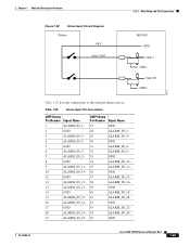
...- 36 GND 37 ALARM_IN_14- 38 ALARM_IN_16- 39 GND 40 ALARM_IN_18- 41 ALARM_IN_20- 42 GND 43 ALARM_IN_22- 44 ALARM_IN_24- 45 GND Cisco ONS 15454 Reference Manual, R8.5 1-59 Chapter 1 Shelf and Backplane Hardware 1.12.1 Wire-Wrap and Pin Connections Figure 1-38 Alarm Input Circuit Diagram Station 48 V max. 2 mA AEP/AIE GND Input 1 VBAT...
...- 36 GND 37 ALARM_IN_14- 38 ALARM_IN_16- 39 GND 40 ALARM_IN_18- 41 ALARM_IN_20- 42 GND 43 ALARM_IN_22- 44 ALARM_IN_24- 45 GND Cisco ONS 15454 Reference Manual, R8.5 1-59 Chapter 1 Shelf and Backplane Hardware 1.12.1 Wire-Wrap and Pin Connections Figure 1-38 Alarm Input Circuit Diagram Station 48 V max. 2 mA AEP/AIE GND Input 1 VBAT...
Reference Manual
Page 112
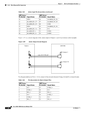
Figure 1-39 Alarm Output Circuit Diagram Station AEP/AIE max. 60 V/100 mA Output 1 Output 16 78474 Use the pin numbers in the example). 1.12.1 Wire-Wrap and Pin Connections Chapter 1 Shelf and Backplane Hardware Table 1-25 Alarm Input Pin Association (continued) AMP Champ Pin Number Signal Name 20 GND 21 ... Pin Number Signal Name 1 N.C. 2 COM_1 3 NO_1 4 N.C. 5 COM_3 6 NO_3 AMP Champ Pin Number Signal Name 27 COM_0 28 N.C. 29 NO_2 30 COM_2 31 N.C. 32 NO_4 1-60 Cisco ONS 15454 Reference Manual, R8.5 78-18106-01
Figure 1-39 Alarm Output Circuit Diagram Station AEP/AIE max. 60 V/100 mA Output 1 Output 16 78474 Use the pin numbers in the example). 1.12.1 Wire-Wrap and Pin Connections Chapter 1 Shelf and Backplane Hardware Table 1-25 Alarm Input Pin Association (continued) AMP Champ Pin Number Signal Name 20 GND 21 ... Pin Number Signal Name 1 N.C. 2 COM_1 3 NO_1 4 N.C. 5 COM_3 6 NO_3 AMP Champ Pin Number Signal Name 27 COM_0 28 N.C. 29 NO_2 30 COM_2 31 N.C. 32 NO_4 1-60 Cisco ONS 15454 Reference Manual, R8.5 78-18106-01
Reference Manual
Page 118
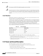
...to Telcordia standards or local practices. 1.14.5 Pilot Fuse Chapter 1 Shelf and Backplane Hardware Caution Do not operate an ONS 15454 without external commands) at power on and about cleaning and maintaining the fan-tray air filter. 1.14.5 Pilot Fuse The...issue 3. 1-66 Cisco ONS 15454 Reference Manual, R8.5 78-18106-01 Cisco recommends the following wiring conventions, but customer conventions prevail: • Red wire for battery connections (-48 VDC) • Black wire for information about every 25-35 minutes in order to the Cisco ONS 15454 Troubleshooting Guide for ...
...to Telcordia standards or local practices. 1.14.5 Pilot Fuse Chapter 1 Shelf and Backplane Hardware Caution Do not operate an ONS 15454 without external commands) at power on and about cleaning and maintaining the fan-tray air filter. 1.14.5 Pilot Fuse The...issue 3. 1-66 Cisco ONS 15454 Reference Manual, R8.5 78-18106-01 Cisco recommends the following wiring conventions, but customer conventions prevail: • Red wire for battery connections (-48 VDC) • Black wire for information about every 25-35 minutes in order to the Cisco ONS 15454 Troubleshooting Guide for ...
Reference Manual
Page 119
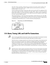
...Hardware 1.16 Alarm, Timing, LAN, and Craft Pin Connections The ONS 15454 has redundant -48 VDC #8 power terminals on the backplane pin field. Figure 1-42 shows the wire-wrap pins on the shelf-assembly backplane. Beneath each wire-wrap pin is a #10-32 bolt. Note The AIC-I as ...indicated in Figure 1-42. 78-18106-01 Cisco ONS 15454 Reference Manual, R8.5 1-67 To install redundant power feeds, ...
...Hardware 1.16 Alarm, Timing, LAN, and Craft Pin Connections The ONS 15454 has redundant -48 VDC #8 power terminals on the backplane pin field. Figure 1-42 shows the wire-wrap pins on the shelf-assembly backplane. Beneath each wire-wrap pin is a #10-32 bolt. Note The AIC-I as ...indicated in Figure 1-42. 78-18106-01 Cisco ONS 15454 Reference Manual, R8.5 1-67 To install redundant power feeds, ...