Hardware Installation Guide
Page 6
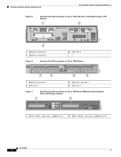
Cisco Access Routers and Cisco Interface Cards Cisco Interface Cards for Cisco Access Routers Figure 5 Interface Card Slot Locations on Cisco 1750 and Cisco 1751 Routers (Cisco 1751 Shown) 1 2 SEE MANUAL BEFORE INSTALLATION Model Cisco 1751 SLOT 1 SLOT 2 VIC 2B-NT/TE CONSOLE SLOT 0 ISDN BRI S/T 1 B1 SEE B2 MANUAL BEFORE OK INSTALLATIOIN ISDN BRI S/T 2 THIS SLOT ACCEPTS ONLY VOICE INTERFACE CARDS 121082 WIC0OK WIC0OK FDX...
Cisco Access Routers and Cisco Interface Cards Cisco Interface Cards for Cisco Access Routers Figure 5 Interface Card Slot Locations on Cisco 1750 and Cisco 1751 Routers (Cisco 1751 Shown) 1 2 SEE MANUAL BEFORE INSTALLATION Model Cisco 1751 SLOT 1 SLOT 2 VIC 2B-NT/TE CONSOLE SLOT 0 ISDN BRI S/T 1 B1 SEE B2 MANUAL BEFORE OK INSTALLATIOIN ISDN BRI S/T 2 THIS SLOT ACCEPTS ONLY VOICE INTERFACE CARDS 121082 WIC0OK WIC0OK FDX...

Hardware Installation Guide
Page 62
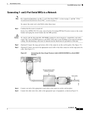
..., EIA/TIA-449, V.35, X.21, DTE/DCE, EIA-530, or EIA-530A serial interface to a Cisco modular router. Figure 34 2-Port A/S Serial WIC Front Panel (WIC-2A/S) Serial ports 41214 SERIAL 1 CONN SERIAL 0 WIC CONN 2A/S SEE MANUAL BEFORE INSTALLATION CONN LEDs OL-12843-01 2 The intrabuilding cable must be shielded and the...
..., EIA/TIA-449, V.35, X.21, DTE/DCE, EIA-530, or EIA-530A serial interface to a Cisco modular router. Figure 34 2-Port A/S Serial WIC Front Panel (WIC-2A/S) Serial ports 41214 SERIAL 1 CONN SERIAL 0 WIC CONN 2A/S SEE MANUAL BEFORE INSTALLATION CONN LEDs OL-12843-01 2 The intrabuilding cable must be shielded and the...
Hardware Installation Guide
Page 65
... shielded and the shield must be grounded at the circuit breaker and taping the circuit breaker into the OFF position. On the Cisco MWR 1941-DC router, turn off . Step 5 Connect the other connector on the surge protector cable. (See Figure 35.) Figure 35 Connecting the... Cisco Surge Protector Cable (CAB-SS-SURGE) to a Serial WAN Interface SERIAL 1 CONN SERIAL 0 WIC CONN 2T SEE MANUAL BEFORE INSTALLATION Surge protection cable (CAB-SS-SURGE) Serial ...
... shielded and the shield must be grounded at the circuit breaker and taping the circuit breaker into the OFF position. On the Cisco MWR 1941-DC router, turn off . Step 5 Connect the other connector on the surge protector cable. (See Figure 35.) Figure 35 Connecting the... Cisco Surge Protector Cable (CAB-SS-SURGE) to a Serial WAN Interface SERIAL 1 CONN SERIAL 0 WIC CONN 2T SEE MANUAL BEFORE INSTALLATION Surge protection cable (CAB-SS-SURGE) Serial ...

Hardware Installation Guide
Page 79
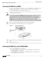
..., as shown in Figure 48. Connect the other end of a straight-through RJ-48C-to-RJ-48C cable SEE MANUAL BEFORE INSTALLATION BRI S/T BRI S/T port (RJ-48C) B1 B2 OK 41193 NT1 device Step 4 Step 5 Step...Straight-through RJ-48C-to-RJ-48C cable to the RJ-48C port on , which indicates that the router is turned off. Check that the OK LED goes on the ISDN BRI S/T WIC. Caution To ... standard for Connecting an ISDN BRI U WIC to a Network • Connecting an ISDN BRI U WIC to the router. ISDN BRI WAN Interface Cards ISDN BRI U WAN Interface Cards To connect an ISDN BRI S/T WIC to a network...
..., as shown in Figure 48. Connect the other end of a straight-through RJ-48C-to-RJ-48C cable SEE MANUAL BEFORE INSTALLATION BRI S/T BRI S/T port (RJ-48C) B1 B2 OK 41193 NT1 device Step 4 Step 5 Step...Straight-through RJ-48C-to-RJ-48C cable to the RJ-48C port on , which indicates that the router is turned off. Check that the OK LED goes on the ISDN BRI S/T WIC. Caution To ... standard for Connecting an ISDN BRI U WIC to a Network • Connecting an ISDN BRI U WIC to the router. ISDN BRI WAN Interface Cards ISDN BRI U WAN Interface Cards To connect an ISDN BRI S/T WIC to a network...
Hardware Installation Guide
Page 83
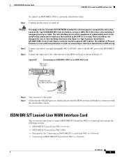
... Cards ISDN BRI S/T Leased-Line WAN Interface Card To connect an ISDN BRI U WIC to a network, follow these steps: Step 1 Confirm that the router is not sufficient protection in order to connect these interfaces metallically to OSP wiring. ISDN BRI S/T Leased-Line WAN Interface Card This section describes how... of Primary Protectors is turned off. Figure 53 Connecting an ISDN BRI U WIC to an ISDN Wall Jack BRI U port (RJ-48C) SEE MANUAL BEFORE INSTALLATION BRI U Straight-through RJ-48C-to-RJ-48C cable to the RJ-48C port on the ISDN BRI U WIC. These interfaces are designed...
... Cards ISDN BRI S/T Leased-Line WAN Interface Card To connect an ISDN BRI U WIC to a network, follow these steps: Step 1 Confirm that the router is not sufficient protection in order to connect these interfaces metallically to OSP wiring. ISDN BRI S/T Leased-Line WAN Interface Card This section describes how... of Primary Protectors is turned off. Figure 53 Connecting an ISDN BRI U WIC to an ISDN Wall Jack BRI U port (RJ-48C) SEE MANUAL BEFORE INSTALLATION BRI U Straight-through RJ-48C-to-RJ-48C cable to the RJ-48C port on the ISDN BRI U WIC. These interfaces are designed...
Hardware Installation Guide
Page 84
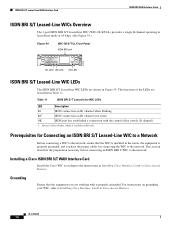
... S/T LL SEE MANUAL BEFORE INSTALLATION B1 LED B2 LED OK LED ISDN BRI S/T Leased-Line WIC LEDs The ISDN BRI S/T leased-line WIC LEDs are working with the central office switch (D channel). 1. For instructions on B1 only. Always off for connecting the WIC to Installing Cisco Interface Cards in Cisco Access Routers. This section describes...
... S/T LL SEE MANUAL BEFORE INSTALLATION B1 LED B2 LED OK LED ISDN BRI S/T Leased-Line WIC LEDs The ISDN BRI S/T leased-line WIC LEDs are working with the central office switch (D channel). 1. For instructions on B1 only. Always off for connecting the WIC to Installing Cisco Interface Cards in Cisco Access Routers. This section describes...

Hardware Installation Guide
Page 85
...to the documentation that came with or open any public telephone operator (PTO)-provided equipment or connection hardware. Connect one end of voltage that the router is turned off. Figure 55 Connecting the ISDN BRI S/T Leased Line Card to an NT1 Device OK LED Straight-through RJ-48C-to-RJ-48C... cable SEE MANUAL BEFORE INSTALLATION BRI S/T LL ISDN BRI leased line interface (RJ-48C) 41191 S/T interface NT1 device Step 4 Step 5 Connect the NT1 device to the ISDN ...
...to the documentation that came with or open any public telephone operator (PTO)-provided equipment or connection hardware. Connect one end of voltage that the router is turned off. Figure 55 Connecting the ISDN BRI S/T Leased Line Card to an NT1 Device OK LED Straight-through RJ-48C-to-RJ-48C... cable SEE MANUAL BEFORE INSTALLATION BRI S/T LL ISDN BRI leased line interface (RJ-48C) 41191 S/T interface NT1 device Step 4 Step 5 Connect the NT1 device to the ISDN ...
Hardware Installation Guide
Page 90
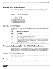
... another DSU/CSU. This section describes the preparation necessary before connecting a 56/64-kbps DSU/CSU WIC to the instructions in Installing Cisco Interface Cards in Cisco Access Routers. For instructions on grounding your serial WIC, refer to provide circuit-switched, dedicated, or leased-line service at 56 kbps. RD ...in Cisco Access Routers. Grounding Ensure that the WIC is installed in Table 12. or 64-kbps port LEDs LED TD RD LP AL CD 41224 SEE MANUAL BEFORE INSTALLATION DSU 56K 56/64-kbps DSU/CSU WIC LEDs The 56/64-kbps DSU/CSU WIC LEDs, are described in the router, ...
... another DSU/CSU. This section describes the preparation necessary before connecting a 56/64-kbps DSU/CSU WIC to the instructions in Installing Cisco Interface Cards in Cisco Access Routers. For instructions on grounding your serial WIC, refer to provide circuit-switched, dedicated, or leased-line service at 56 kbps. RD ...in Cisco Access Routers. Grounding Ensure that the WIC is installed in Table 12. or 64-kbps port LEDs LED TD RD LP AL CD 41224 SEE MANUAL BEFORE INSTALLATION DSU 56K 56/64-kbps DSU/CSU WIC LEDs The 56/64-kbps DSU/CSU WIC LEDs, are described in the router, ...

Hardware Installation Guide
Page 91
... cable to a Network OL-12845-01 3 Check that the CD LED comes on, which indicates that the router is communicating with the DSU/CSU at the 56/64-kbps service provider's central office. T1/FT1 DSU/CSU... 56/64-kbps DSU/CSU WIC to a Network To connect a 56/64-kbps DSU/CSU WIC to the router. Figure 57 Connecting the 56/64-kbps DSU/CSU WIC to a 56/64-kbps Services Wall Jack Switched 56.../64-kbps port (RJ-48S) SEE MANUAL BEFORE INSTALLATION DSU 56K Straight-through RJ-48S-to-RJ-48S cable to a network. DSU/CSU WAN Interface...
... cable to a Network OL-12845-01 3 Check that the CD LED comes on, which indicates that the router is communicating with the DSU/CSU at the 56/64-kbps service provider's central office. T1/FT1 DSU/CSU... 56/64-kbps DSU/CSU WIC to a Network To connect a 56/64-kbps DSU/CSU WIC to the router. Figure 57 Connecting the 56/64-kbps DSU/CSU WIC to a 56/64-kbps Services Wall Jack Switched 56.../64-kbps port (RJ-48S) SEE MANUAL BEFORE INSTALLATION DSU 56K Straight-through RJ-48S-to-RJ-48S cable to a network. DSU/CSU WAN Interface...
Hardware Installation Guide
Page 95
... Cards Supported Platforms Connecting a T1/FT1 DSU/CSU WIC to a Network To connect a T1/FT1 DSU/CSU WIC to a network, follow the instructions that appear. Access Cisco Feature Navigator at the T1 service provider's central office. Connect the other end of the straight-through RJ-48C-to-RJ-48C cable 41196 Step...) SEE MANUAL BEFORE INSTALLATION LP AL CD LOOP BACK T1 DSU/CSU DSU CSU T1 Straight-through RJ-48C-to-RJ-48C cable to the T1 wall jack, as shown in Figure 61. If you do not have an account or have an account on , which means that the router is communicating...
... Cards Supported Platforms Connecting a T1/FT1 DSU/CSU WIC to a Network To connect a T1/FT1 DSU/CSU WIC to a network, follow the instructions that appear. Access Cisco Feature Navigator at the T1 service provider's central office. Connect the other end of the straight-through RJ-48C-to-RJ-48C cable 41196 Step...) SEE MANUAL BEFORE INSTALLATION LP AL CD LOOP BACK T1 DSU/CSU DSU CSU T1 Straight-through RJ-48C-to-RJ-48C cable to the T1 wall jack, as shown in Figure 61. If you do not have an account or have an account on , which means that the router is communicating...

Hardware Installation Guide
Page 98
...Applies only to the network and operating normally. Access Cisco Feature Navigator at the login dialog box and ...Panels ADASDLSL SEE MANUAL BEFORE INSTALLATION CD LP OK WIC 1ADSL SHDSL SEE MANUAL BEFORE INSTALLATION CD LP OK WIC 1SHDSL ADSL SEE MANUAL BEFORE INSTALLATION WIC 1ADSL IDG CD LP OK ADSL SEE MANUAL BEFORE INSTALLATION ... section 7.1.2.5.3. OL-12846-01 2 Normal operation. Finding Support Information for Cisco Interface Cards. Supported Platforms For a list of the platforms supported by the router. ADSL WICs DSL Interface Cards Note The term dying gasp refers to...
...Applies only to the network and operating normally. Access Cisco Feature Navigator at the login dialog box and ...Panels ADASDLSL SEE MANUAL BEFORE INSTALLATION CD LP OK WIC 1ADSL SHDSL SEE MANUAL BEFORE INSTALLATION CD LP OK WIC 1SHDSL ADSL SEE MANUAL BEFORE INSTALLATION WIC 1ADSL IDG CD LP OK ADSL SEE MANUAL BEFORE INSTALLATION ... section 7.1.2.5.3. OL-12846-01 2 Normal operation. Finding Support Information for Cisco Interface Cards. Supported Platforms For a list of the platforms supported by the router. ADSL WICs DSL Interface Cards Note The term dying gasp refers to...

Hardware Installation Guide
Page 104
...RJ-11 Connector RJ-45 Connector Figure 67 LEDs ADSLoISDN HWIC Front Panel LEDs LEDs 127118 LP CD OK ADSL SEE MANUAL BEFORE INSTALLATION LP B1 CD B2 SEE MANUAL OK OK BEFORE INSTALLATION ADSL ISDN BRI S/T RJ-11 Connector RJ-11 Connector RJ-45 Connector Table 18 ADSL ... ISDN port. LEDs on the first B channel. ISDN port has established a connection with DSLAMs. Enabled when the card is detected by the router. Lit when the unit is connected to the network and operating normally. This LED blinks slowly while downloading ADSL firmware, and blinks rapidly while training...
...RJ-11 Connector RJ-45 Connector Figure 67 LEDs ADSLoISDN HWIC Front Panel LEDs LEDs 127118 LP CD OK ADSL SEE MANUAL BEFORE INSTALLATION LP B1 CD B2 SEE MANUAL OK OK BEFORE INSTALLATION ADSL ISDN BRI S/T RJ-11 Connector RJ-11 Connector RJ-45 Connector Table 18 ADSL ... ISDN port. LEDs on the first B channel. ISDN port has established a connection with DSLAMs. Enabled when the card is detected by the router. Lit when the unit is connected to the network and operating normally. This LED blinks slowly while downloading ADSL firmware, and blinks rapidly while training...
Hardware Installation Guide
Page 107
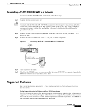
... card to the no shut command in Figure 69. To connect the card to the network, you must configure the DSL interface card in the router to a 4-wire patch panel, use a Y-cable as shown in Figure 68. Figure 69 Connecting a G.SHDSL Card to a Patch Panel With a Y-Cable SHDSL port (RJ-11...) WIC 1SHDSL V2 SHDSL SEE MANUAL BEFORE INSTALLATION CD LP OK Patch panel RJ-11 twisted-pair cables 10 11 12 13 14 103235 Step 4 Step 5 Turn on , indicating that the...
... card to the no shut command in Figure 69. To connect the card to the network, you must configure the DSL interface card in the router to a 4-wire patch panel, use a Y-cable as shown in Figure 68. Figure 69 Connecting a G.SHDSL Card to a Patch Panel With a Y-Cable SHDSL port (RJ-11...) WIC 1SHDSL V2 SHDSL SEE MANUAL BEFORE INSTALLATION CD LP OK Patch panel RJ-11 twisted-pair cables 10 11 12 13 14 103235 Step 4 Step 5 Turn on , indicating that the...
Hardware Installation Guide
Page 108
...standard for electromagnetic compatibility and safety, connect the HWIC-ADSL-B/ST or HWIC-ADSLI-B/ST ISDN BRI S/T port only to the online document Cisco Modular Access Router Cable Specifications for use as intra-building interfaces only (Type 2 or Type 4 ports as described in order to connect these steps: Step...straight-through cable to establish connection between the HWIC and a network device. • Cisco HWIC-4SHDSL-Use a standard RJ-45 straight-through RJ-45-to-RJ-45 cable LP CD B1 OK B2 SEE MANUAL OK BEFORE ADSL ISDN BRI S/T INSTALLATION BRI S/T port (RJ-45) 127428 NT1 ...
...standard for electromagnetic compatibility and safety, connect the HWIC-ADSL-B/ST or HWIC-ADSLI-B/ST ISDN BRI S/T port only to the online document Cisco Modular Access Router Cable Specifications for use as intra-building interfaces only (Type 2 or Type 4 ports as described in order to connect these steps: Step...straight-through cable to establish connection between the HWIC and a network device. • Cisco HWIC-4SHDSL-Use a standard RJ-45 straight-through RJ-45-to-RJ-45 cable LP CD B1 OK B2 SEE MANUAL OK BEFORE ADSL ISDN BRI S/T INSTALLATION BRI S/T port (RJ-45) 127428 NT1 ...

Hardware Installation Guide
Page 114
..., see the "Obtaining Documentation, Obtaining Support, and Security Guidelines" section on Cisco 1700 Series, Cisco 2600 Series, Cisco 3600 Series, and Cisco 3700 Series Routers, Cisco IOS Releases 12.2(8)YN and 12.2(13)T - Configuring a Cisco 1700/2600/3600 ADSL WIC With RFC1483 Routing Using ...Cisco 2600 Series Routers, Cisco IOS Release 12.2(4)XL - Configuring a Cisco 1700/2600/3600 ADSL WIC With IP Unnumbered E0, PPPoA, PPP-PAP, and Manually Configured Local LAN Devices - Enhanced Voice and QoS for ADSL and G.SHDSL on Cisco 1700, Cisco 2600, and Cisco 3600 Series Routers, Cisco...
..., see the "Obtaining Documentation, Obtaining Support, and Security Guidelines" section on Cisco 1700 Series, Cisco 2600 Series, Cisco 3600 Series, and Cisco 3700 Series Routers, Cisco IOS Releases 12.2(8)YN and 12.2(13)T - Configuring a Cisco 1700/2600/3600 ADSL WIC With RFC1483 Routing Using ...Cisco 2600 Series Routers, Cisco IOS Release 12.2(4)XL - Configuring a Cisco 1700/2600/3600 ADSL WIC With IP Unnumbered E0, PPPoA, PPP-PAP, and Manually Configured Local LAN Devices - Enhanced Voice and QoS for ADSL and G.SHDSL on Cisco 1700, Cisco 2600, and Cisco 3600 Series Routers, Cisco...
Hardware Installation Guide
Page 119
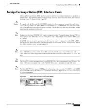
...FXS/DID cards (VIC-4FXS/DID) only to intrabuilding or non-exposed wiring or cabling. Note Cisco 2600XM series, Cisco 2691, Cisco 2800 series, Cisco 3600 series, Cisco 3700 series, and Cisco 3800 series routers support DID on page 13. The intrabuilding cable must be shielded and the shield must be configured..., fax machine, or similar device. Figure 79 2-Port FXS Card Front Panel (VIC-2FXS) VIC FXS 1 SEE MANUAL BEFORE INSTALLATION 0 IN USE IN USE 41218 OL-12847-01 3 Note The Cisco 1751 router can support four 4-port FXS/DID VICs, up to a maximum of 1 or less. Note The...
...FXS/DID cards (VIC-4FXS/DID) only to intrabuilding or non-exposed wiring or cabling. Note Cisco 2600XM series, Cisco 2691, Cisco 2800 series, Cisco 3600 series, Cisco 3700 series, and Cisco 3800 series routers support DID on page 13. The intrabuilding cable must be shielded and the shield must be configured..., fax machine, or similar device. Figure 79 2-Port FXS Card Front Panel (VIC-2FXS) VIC FXS 1 SEE MANUAL BEFORE INSTALLATION 0 IN USE IN USE 41218 OL-12847-01 3 Note The Cisco 1751 router can support four 4-port FXS/DID VICs, up to a maximum of 1 or less. Note The...
Hardware Installation Guide
Page 120
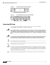
Warning For connections outside the building where the equipment is active. Step 1 Confirm that the router is activated by an incoming call. Note Ports on the card. (See Figure 82.) OL-12847-01 4 Caution To comply with integral circuit protection: FXS. ... wiring or cabling. Foreign Exchange Station (FXS) Interface Cards Figure 80 2-Port FXS Card Front Panel (VIC2-2FXS) IN USE 89041 IN USE VIC22FXS ! 1 SEE MANUAL BEFORE INSTALLATION 0 Figure 81 4-Port FXS/DID Card Front Panel (VIC-4FXS/DID) Voice Interface Cards 65683 VIC 4FXS/DID 3 2 1 0 IN USE Connecting FXS Cards...
Warning For connections outside the building where the equipment is active. Step 1 Confirm that the router is activated by an incoming call. Note Ports on the card. (See Figure 82.) OL-12847-01 4 Caution To comply with integral circuit protection: FXS. ... wiring or cabling. Foreign Exchange Station (FXS) Interface Cards Figure 80 2-Port FXS Card Front Panel (VIC2-2FXS) IN USE 89041 IN USE VIC22FXS ! 1 SEE MANUAL BEFORE INSTALLATION 0 Figure 81 4-Port FXS/DID Card Front Panel (VIC-4FXS/DID) Voice Interface Cards 65683 VIC 4FXS/DID 3 2 1 0 IN USE Connecting FXS Cards...

Hardware Installation Guide
Page 123
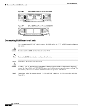
Note Ports on the card. (See Figure 86.) Figure 86 Connecting an FXO Card RJ-11 ports IN USE IN USE VIC FXS 1 SEE MANUAL BEFORE INSTALLATION 0 Straight-through a telephone wall outlet. The intrabuilding cable must be shielded and the shield must be grounded at both ends. Receive and ...-to-RJ-11 cable 41195 Step 3 RJ-11 wall jack Connect the other end to an RJ-11 telephone wall outlet. Step 1 Confirm that the router is a signaling technique for electromagnetic compatibility and safety, connect the 2-port FXO card (VIC2-2FXO) only to a PBX. Caution To comply with the ...
Note Ports on the card. (See Figure 86.) Figure 86 Connecting an FXO Card RJ-11 ports IN USE IN USE VIC FXS 1 SEE MANUAL BEFORE INSTALLATION 0 Straight-through a telephone wall outlet. The intrabuilding cable must be shielded and the shield must be grounded at both ends. Receive and ...-to-RJ-11 cable 41195 Step 3 RJ-11 wall jack Connect the other end to an RJ-11 telephone wall outlet. Step 1 Confirm that the router is a signaling technique for electromagnetic compatibility and safety, connect the 2-port FXO card (VIC2-2FXO) only to a PBX. Caution To comply with the ...
Hardware Installation Guide
Page 124
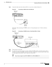
... card are colored brown. Caution Do not connect an E&M interface directly to intra-building or non-exposed wiring or cabling. Step 1 Confirm that the router is still turned off. Caution To comply with the Telcordia GR-1089 NEBS standard for electromagnetic compatibility and safety, connect the 2-port E&M card (VIC2...8 Receive and Transmit (E&M) Interface Cards Voice Interface Cards Figure 87 2-Port E&M Card Front Panel (VIC-2E/M) IN USE 41219 IN USE VIC E&M 1 SEE MANUAL BEFORE INSTALLATION 0 Figure 88 2-Port E&M Card Front Panel (VIC2-2E/M) IN USE 89039 IN USE VIC22E/M 1 SEE...
... card are colored brown. Caution Do not connect an E&M interface directly to intra-building or non-exposed wiring or cabling. Step 1 Confirm that the router is still turned off. Caution To comply with the Telcordia GR-1089 NEBS standard for electromagnetic compatibility and safety, connect the 2-port E&M card (VIC2...8 Receive and Transmit (E&M) Interface Cards Voice Interface Cards Figure 87 2-Port E&M Card Front Panel (VIC-2E/M) IN USE 41219 IN USE VIC E&M 1 SEE MANUAL BEFORE INSTALLATION 0 Figure 88 2-Port E&M Card Front Panel (VIC2-2E/M) IN USE 89039 IN USE VIC22E/M 1 SEE...

Hardware Installation Guide
Page 126
... S/T 0 Figure 92 2-Port ISDN BRI Card Front Panel (VIC2-2BRI-NT/TE) B1 SEE VIC22BRI-NT/TE B2 OK MANUAL BEFORE INSTALLATION ISDN BRI S/T 1 ISDN BRI S/T 0 89037 ISDN BRI Card Considerations Note Cisco ISDN BRI interface cards support voice ISDN traffic only. Slot 1 should remain empty. OL-12847-01 10 You can... interface card. The intrabuilding cable must be grounded at both ISDN BRI NT/TE voice interface cards. ISDN BRI Interface Cards Voice Interface Cards The Cisco 1751 and Cisco 1760 routers, and the Cisco ICS 7750 platform support both ends.
... S/T 0 Figure 92 2-Port ISDN BRI Card Front Panel (VIC2-2BRI-NT/TE) B1 SEE VIC22BRI-NT/TE B2 OK MANUAL BEFORE INSTALLATION ISDN BRI S/T 1 ISDN BRI S/T 0 89037 ISDN BRI Card Considerations Note Cisco ISDN BRI interface cards support voice ISDN traffic only. Slot 1 should remain empty. OL-12847-01 10 You can... interface card. The intrabuilding cable must be grounded at both ISDN BRI NT/TE voice interface cards. ISDN BRI Interface Cards Voice Interface Cards The Cisco 1751 and Cisco 1760 routers, and the Cisco ICS 7750 platform support both ends.


