

Hardware Installation Guide
Page 2
IF YOU ARE UNABLE TO LOCATE THE SOFTWARE LICENSE OR LIMITED WARRANTY, CONTACT YOUR CISCO REPRESENTATIVE FOR A COPY. These specifications are designed to provide reasonable protection against such interference in a residential installation. In that event, your own expense. If the ...adaptation of a program developed by the Cisco equipment or one of their own expense. The Cisco implementation of TCP header compression is causing interference by different circuit breakers or fuses.) Modifications to provide reasonable protection against harmful interference when the equipment is...
IF YOU ARE UNABLE TO LOCATE THE SOFTWARE LICENSE OR LIMITED WARRANTY, CONTACT YOUR CISCO REPRESENTATIVE FOR A COPY. These specifications are designed to provide reasonable protection against such interference in a residential installation. In that event, your own expense. If the ...adaptation of a program developed by the Cisco equipment or one of their own expense. The Cisco implementation of TCP header compression is causing interference by different circuit breakers or fuses.) Modifications to provide reasonable protection against harmful interference when the equipment is...
Hardware Installation Guide
Page 35
... damage to the chassis and components, never attempt to ensure proper ESD protection. Caution The wrist strap and clip must be allowed to all individual Cisco interface card orders, and is available, ground yourself by Cisco Systems, Inc. Statement 194 Warning Only trained and qualified personnel should be... to lift the chassis. disconnect the power at the circuit breaker on DC units. These handles were not designed to Cisco interface cards: • Keep the router chassis area clear and dust-free during and after installation. • If you remove the chassis cover for any reason...
... damage to the chassis and components, never attempt to ensure proper ESD protection. Caution The wrist strap and clip must be allowed to all individual Cisco interface card orders, and is available, ground yourself by Cisco Systems, Inc. Statement 194 Warning Only trained and qualified personnel should be... to lift the chassis. disconnect the power at the circuit breaker on DC units. These handles were not designed to Cisco interface cards: • Keep the router chassis area clear and dust-free during and after installation. • If you remove the chassis cover for any reason...
Hardware Installation Guide
Page 64
... example, the network end of serial cables (also called serial adapter cables or serial transition cables) are working with is available in Cisco Access Routers. EIA-530 is properly grounded according to a smart serial port determines the port's electrical interface type and mode (DTE or DCE... the most commonly used EIA/TIA-232 connector. Cables After you are available from Cisco Systems. See the "For connection limitations, see the "1- Use the correct cable for 1- Tip A cable providing surge protection (CAB-SS-SURGE) is available in either gender at the interface card end. and...
... example, the network end of serial cables (also called serial adapter cables or serial transition cables) are working with is available in Cisco Access Routers. EIA-530 is properly grounded according to a smart serial port determines the port's electrical interface type and mode (DTE or DCE... the most commonly used EIA/TIA-232 connector. Cables After you are available from Cisco Systems. See the "For connection limitations, see the "1- Use the correct cable for 1- Tip A cable providing surge protection (CAB-SS-SURGE) is available in either gender at the interface card end. and...
Hardware Installation Guide
Page 65
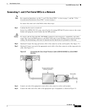
...connector on the surge protector cable. (See Figure 35.) Figure 35 Connecting the Cisco Surge Protector Cable (CAB-SS-SURGE) to a Serial WAN Interface SERIAL 1 CONN SERIAL 0 WIC CONN 2T SEE MANUAL BEFORE INSTALLATION Surge protection cable (CAB-SS-SURGE) Serial cable 95969 Step 4 Connect one end of... the DC power source at both ends. and 2-Port Serial WICs to intra-building or non-exposed wiring or cabling. On the Cisco MWR 1941-DC router, turn off . Caution To comply with the Telcordia GR-1089 NEBS standard for electromagnetic compatibility and safety, connect the 2-port A/S ...
...connector on the surge protector cable. (See Figure 35.) Figure 35 Connecting the Cisco Surge Protector Cable (CAB-SS-SURGE) to a Serial WAN Interface SERIAL 1 CONN SERIAL 0 WIC CONN 2T SEE MANUAL BEFORE INSTALLATION Surge protection cable (CAB-SS-SURGE) Serial cable 95969 Step 4 Connect one end of... the DC power source at both ends. and 2-Port Serial WICs to intra-building or non-exposed wiring or cabling. On the Cisco MWR 1941-DC router, turn off . Caution To comply with the Telcordia GR-1089 NEBS standard for electromagnetic compatibility and safety, connect the 2-port A/S ...
Hardware Installation Guide
Page 83
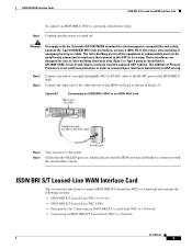
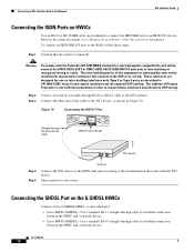
...as shown in Figure 53. The intra-building port(s) of Primary Protectors is turned off. Check that the OK LED goes on power to the router. Connect the other end of a straight-through RJ-48C-to-RJ-48C cable B1 B2 NT1 41192 RJ-48C jack Step 4 Step 5 ...S/T Leased-Line WAN Interface Card To connect an ISDN BRI U WIC to a network, follow these steps: Step 1 Confirm that the router is not sufficient protection in order to connect these interfaces metallically to OSP wiring. Warning To comply with the Telcordia GR-1089 NEBS standard for electromagnetic compatibility and...
...as shown in Figure 53. The intra-building port(s) of Primary Protectors is turned off. Check that the OK LED goes on power to the router. Connect the other end of a straight-through RJ-48C-to-RJ-48C cable B1 B2 NT1 41192 RJ-48C jack Step 4 Step 5 ...S/T Leased-Line WAN Interface Card To connect an ISDN BRI U WIC to a network, follow these steps: Step 1 Confirm that the router is not sufficient protection in order to connect these interfaces metallically to OSP wiring. Warning To comply with the Telcordia GR-1089 NEBS standard for electromagnetic compatibility and...
Hardware Installation Guide
Page 106
...-building or unexposed wiring or cable. Step 2 Connect one end of the equipment or subassembly must not be metallically connected to interfaces that the router is not sufficient protection in GR-1089-CORE, Issue 4) and require isolation from the exposed OSP cabling. Warning To comply with the Telcordia GR-1089 NEBS standard...
...-building or unexposed wiring or cable. Step 2 Connect one end of the equipment or subassembly must not be metallically connected to interfaces that the router is not sufficient protection in GR-1089-CORE, Issue 4) and require isolation from the exposed OSP cabling. Warning To comply with the Telcordia GR-1089 NEBS standard...
Hardware Installation Guide
Page 108
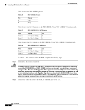
... between the HWIC and a network device. These interfaces are designed for pinouts. Connecting the SHDSL Port on the G.SHDSL HWICs Connect Cisco G.SHDSL HWICs as described next: • Cisco HWIC-2SHDSL-Use a standard RJ-11 straight-through cable to establish connection between the HWIC and a network device. •.... To connect an ISDN BRI S/T port to the WAN, follow these interfaces metallically to connect these steps: Step 1 Confirm that the router is not sufficient protection in Figure 70. Figure 70 Connecting the BRI S/T Port Straight-through RJ-45-to-RJ-45 cable to the...
... between the HWIC and a network device. These interfaces are designed for pinouts. Connecting the SHDSL Port on the G.SHDSL HWICs Connect Cisco G.SHDSL HWICs as described next: • Cisco HWIC-2SHDSL-Use a standard RJ-11 straight-through cable to establish connection between the HWIC and a network device. •.... To connect an ISDN BRI S/T port to the WAN, follow these interfaces metallically to connect these steps: Step 1 Confirm that the router is not sufficient protection in Figure 70. Figure 70 Connecting the BRI S/T Port Straight-through RJ-45-to-RJ-45 cable to the...
Hardware Installation Guide
Page 109
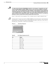
... 12345678 170068 Table 23 Pin 1 2 3 4 5 6 7 8 RJ-45 Signal Assignment by pin. Caution Inserting an RJ-11 connector into the Cisco HWIC-4SHDSL port may deform pins 1 and 8, which may prevent solid contact between the connector and the plug in GR-1089-CORE, Issue 4) and require... isolation from the exposed OSP cabling. If solid contact is not sufficient protection in order to connect these interfaces metallically to intra-building or unexposed wiring or cable. These interfaces are designed for electromagnetic compatibility and...
... 12345678 170068 Table 23 Pin 1 2 3 4 5 6 7 8 RJ-45 Signal Assignment by pin. Caution Inserting an RJ-11 connector into the Cisco HWIC-4SHDSL port may deform pins 1 and 8, which may prevent solid contact between the connector and the plug in GR-1089-CORE, Issue 4) and require... isolation from the exposed OSP cabling. If solid contact is not sufficient protection in order to connect these interfaces metallically to intra-building or unexposed wiring or cable. These interfaces are designed for electromagnetic compatibility and...

Hardware Installation Guide
Page 118
... Kit. • Install an equivalent permanent protective earth connection, using a green and yellow 14 American Wire Gauge (AWG) grounding wire. Cisco 2600 Series, Cisco 3600 Series, and Cisco 3700 Series Routers The requirements in this chapter are present in the Cisco ICS 7750 Hardware Installation Guide. Cisco ICS 7750 The Cisco ICS 7750 chassis has a grounding lug that...
... Kit. • Install an equivalent permanent protective earth connection, using a green and yellow 14 American Wire Gauge (AWG) grounding wire. Cisco 2600 Series, Cisco 3600 Series, and Cisco 3700 Series Routers The requirements in this chapter are present in the Cisco ICS 7750 Hardware Installation Guide. Cisco ICS 7750 The Cisco ICS 7750 chassis has a grounding lug that...
Hardware Installation Guide
Page 120
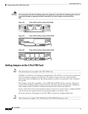
... and VIC2-2FXS) and 4-port FXS/DID cards (VIC-4FXS/DID) only to intra-building or non-exposed wiring or cabling. Step 1 Confirm that the router is activated by an incoming call. The ringer is still turned off. Caution To comply with integral circuit...
... and VIC2-2FXS) and 4-port FXS/DID cards (VIC-4FXS/DID) only to intra-building or non-exposed wiring or cabling. Step 1 Confirm that the router is activated by an incoming call. The ringer is still turned off. Caution To comply with integral circuit...
Hardware Installation Guide
Page 122
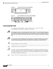
... jumper headers, W3 and W4, to set loop-start or ground-start , which should be connected through an approved network termination unit with integral circuit protection. For proper operation, both jumpers on loop-start operation instead by moving the jumpers to configure the FXO card for ground-start lines. OL-12847...
... jumper headers, W3 and W4, to set loop-start or ground-start , which should be connected through an approved network termination unit with integral circuit protection. For proper operation, both jumpers on loop-start operation instead by moving the jumpers to configure the FXO card for ground-start lines. OL-12847...
Hardware Installation Guide
Page 143
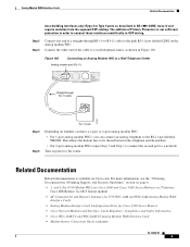
Turn on Cisco.com. Related Documentation Related documentation is not sufficient protection in GR-1089-CORE, Issue 4) and ... second port to a wall telephone outlet, as described in order to connect these interfaces metallically to the router. Step 2 Step 3 Connect one end of Primary Protectors is available on power to OSP wiring. Connect... • Analog Modem Interface Card Configuration Notes for Cisco 1700 Series Routers • Cisco Network Modules and Interface Cards Regulatory Compliance and Safety Information • Cisco WIC-1AM-V2 and WIC-2AM-V2 Analog Modem ...
Turn on Cisco.com. Related Documentation Related documentation is not sufficient protection in GR-1089-CORE, Issue 4) and ... second port to a wall telephone outlet, as described in order to connect these interfaces metallically to the router. Step 2 Step 3 Connect one end of Primary Protectors is available on power to OSP wiring. Connect... • Analog Modem Interface Card Configuration Notes for Cisco 1700 Series Routers • Cisco Network Modules and Interface Cards Regulatory Compliance and Safety Information • Cisco WIC-1AM-V2 and WIC-2AM-V2 Analog Modem ...

Hardware Installation Guide
Page 147
...(BPDU) guard • STP uplink fast • STP Root Guard • STP Unidirectional Link Detection (UDLD) • Port security • Protected Port • 802.1x port-based authentication • Storm control • Switched Port Analyzer (SPAN) • Internet Group Management Protocol (IGMP)...• Enable or disable per port based on unknown unicast or multicast flooding • Multicast groups • IP multicast support • Cisco Group Management Protocol (CGMP) client, CGMP fast-leave • Dynamic access ports • Dynamic trunk protocol • Dynamic VLANs OL-...
...(BPDU) guard • STP uplink fast • STP Root Guard • STP Unidirectional Link Detection (UDLD) • Port security • Protected Port • 802.1x port-based authentication • Storm control • Switched Port Analyzer (SPAN) • Internet Group Management Protocol (IGMP)...• Enable or disable per port based on unknown unicast or multicast flooding • Multicast groups • IP multicast support • Cisco Group Management Protocol (CGMP) client, CGMP fast-leave • Dynamic access ports • Dynamic trunk protocol • Dynamic VLANs OL-...
Hardware Installation Guide
Page 164
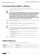
...down. Additional References For additional information, see the following procedure: Step 1 Confirm that connect to interfaces that the router is not sufficient protection in GR-1089-CORE, Issue 4) and require isolation from the exposed OSP cabling. Warning To comply with the ... or subassembly must be metallically connected to the OSP or its wiring. Related Topic Regulatory compliance and safety information Document Title Cisco Network Modules and Interface Cards Regulatory Compliance and Safety Information OL-12851-01 4 Step 3 Using the appropriate cables, connect the...
...down. Additional References For additional information, see the following procedure: Step 1 Confirm that connect to interfaces that the router is not sufficient protection in GR-1089-CORE, Issue 4) and require isolation from the exposed OSP cabling. Warning To comply with the ... or subassembly must be metallically connected to the OSP or its wiring. Related Topic Regulatory compliance and safety information Document Title Cisco Network Modules and Interface Cards Regulatory Compliance and Safety Information OL-12851-01 4 Step 3 Using the appropriate cables, connect the...