
Hardware Installation Guide
Page 24
... Modules Chapter 1 Overview of Cisco Network Modules for Cisco Access Routers Table 1-3 Cabling for Cisco Network Modules Connection Type Connector Type, Cable Color Alarm Interface Connections To alarm interface 50-pin D patch panels or main distribution frame Analog Dialup 300 bps to 33.6 kbps RJ-11 analog dialup ATM ATM to ADSL T3 ATM... core Note Maximum path length of 45 km (27.9 miles) for single-mode long (SML) reach and 15 km (9.3 miles) for part numbers 1-10 Cisco Network Modules Hardware Installation Guide OL-2485-20 NM-1ATM-25 NM-1A-T3 NM-1A-T3/E3 NM-1A-E3 NM-1A-T3/E3...
... Modules Chapter 1 Overview of Cisco Network Modules for Cisco Access Routers Table 1-3 Cabling for Cisco Network Modules Connection Type Connector Type, Cable Color Alarm Interface Connections To alarm interface 50-pin D patch panels or main distribution frame Analog Dialup 300 bps to 33.6 kbps RJ-11 analog dialup ATM ATM to ADSL T3 ATM... core Note Maximum path length of 45 km (27.9 miles) for single-mode long (SML) reach and 15 km (9.3 miles) for part numbers 1-10 Cisco Network Modules Hardware Installation Guide OL-2485-20 NM-1ATM-25 NM-1A-T3 NM-1A-T3/E3 NM-1A-E3 NM-1A-T3/E3...

Hardware Installation Guide
Page 25
Chapter 1 Overview of Cisco Network Modules for Cisco Access Routers Cabling for Cisco Network Modules Table 1-3 Cabling for Cisco Network Modules (continued) Connection Type Ethernet Ethernet Connector Type, Cable Color RJ-45, yellow DB-15 Cable 10BASE-T Category 5 or above UTP Attachment unit interface (...-1G NME-X-23ES-1G-P NME-XD-24ES-1S-P NME-XD-48ES-2S-P NM-1FE-FX NM-1FE-FX-V2 NM-1FE-SMF OL-2485-20 Cisco Network Modules Hardware Installation Guide...
Chapter 1 Overview of Cisco Network Modules for Cisco Access Routers Cabling for Cisco Network Modules Table 1-3 Cabling for Cisco Network Modules (continued) Connection Type Ethernet Ethernet Connector Type, Cable Color RJ-45, yellow DB-15 Cable 10BASE-T Category 5 or above UTP Attachment unit interface (...-1G NME-X-23ES-1G-P NME-XD-24ES-1S-P NME-XD-48ES-2S-P NM-1FE-FX NM-1FE-FX-V2 NM-1FE-SMF OL-2485-20 Cisco Network Modules Hardware Installation Guide...
Hardware Installation Guide
Page 59
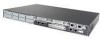
... Cisco Access Routers Figure 2-4 Inserting a Slot Divider into a Network Module Slot 117050 T D M 0 S L O T 2 S L O T 0 SAG==ESACP0ET/1ED AAG==EFLIDN0X/K0 A F S L PVDM2 PVDM1 PVDM0 AIM1 S L O T 3 A F S S L L O T 1 AIM0 Step 3 Step 4 Push the slot divider in a Network Module Slot T D M 0 S L O T 2 S L O T 0 S L O A= S= ASCPETED GE 0/1 AAG==EFLIDN0X/K0 T 3 A F S S L A L O T F 1 S L PVDM2 PVDM1 PVDM0 AIM1 AIM0 117051 OL-2485-20 Cisco Network Modules Hardware Installation Guide 2-11...
... Cisco Access Routers Figure 2-4 Inserting a Slot Divider into a Network Module Slot 117050 T D M 0 S L O T 2 S L O T 0 SAG==ESACP0ET/1ED AAG==EFLIDN0X/K0 A F S L PVDM2 PVDM1 PVDM0 AIM1 S L O T 3 A F S S L L O T 1 AIM0 Step 3 Step 4 Push the slot divider in a Network Module Slot T D M 0 S L O T 2 S L O T 0 S L O A= S= ASCPETED GE 0/1 AAG==EFLIDN0X/K0 T 3 A F S S L A L O T F 1 S L PVDM2 PVDM1 PVDM0 AIM1 AIM0 117051 OL-2485-20 Cisco Network Modules Hardware Installation Guide 2-11...

Hardware Installation Guide
Page 64
...2 Step 3 Turn off electrical power to the network and power up the router. Remove the blank faceplates installed over the slot you feel the edge connector seat securely into place until you intend to use. (See the "...DC power supply, remove the tape from the rear panel of the circuit breaker to the ON position. Installing Cisco Network Modules in Cisco Access Routers Chapter 2 Installing Cisco Network Modules in Cisco Access Routers Figure 2-10 Installing Single-Wide and Extended Single-Wide Network Modules in Cisco Access Routers ACT H9998 ETHERNET 0 WO SERIAL ASYNC 15 11...
...2 Step 3 Turn off electrical power to the network and power up the router. Remove the blank faceplates installed over the slot you feel the edge connector seat securely into place until you intend to use. (See the "...DC power supply, remove the tape from the rear panel of the circuit breaker to the ON position. Installing Cisco Network Modules in Cisco Access Routers Chapter 2 Installing Cisco Network Modules in Cisco Access Routers Figure 2-10 Installing Single-Wide and Extended Single-Wide Network Modules in Cisco Access Routers ACT H9998 ETHERNET 0 WO SERIAL ASYNC 15 11...
Hardware Installation Guide
Page 65
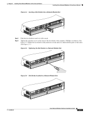
... the network module form factor you are installing. (See the "Preparing Cisco Router Slots for Network Module Installation" section on page 2-8.) Confirm that network module levers are in the open position away from the network module faceplate. (See Figure 2-11.) Figure 2-11 Open and Closed Positions for Double-Wide and Extended Double-Wide Network...
... the network module form factor you are installing. (See the "Preparing Cisco Router Slots for Network Module Installation" section on page 2-8.) Confirm that network module levers are in the open position away from the network module faceplate. (See Figure 2-11.) Figure 2-11 Open and Closed Positions for Double-Wide and Extended Double-Wide Network...

Hardware Installation Guide
Page 67
...the circuit breaker in to channel ESD voltages to ground. • (For the Cisco MWR 1941-DC router) Turn off electrical power to ground, do not remove the wire from the router slot. Caution To avoid damaging the network module, always handle the network module ... cables from Cisco Access Routers WO SERIAL ASYNC 15 11 14 10 13 9 12 8 15 11 14 10 13 9 12 8 ASYNC 24-31 ASYNC 8-15 7 3 6 2 5 1 4 0 7 3 6 2 5 1 4 0 ASYNC 16-23 ASYNC 0-7 EN ACT 121074 2 1 1 Router chassis 2 Single-wide network module OL-2485-20 Cisco Network Modules Hardware...
...the circuit breaker in to channel ESD voltages to ground. • (For the Cisco MWR 1941-DC router) Turn off electrical power to ground, do not remove the wire from the router slot. Caution To avoid damaging the network module, always handle the network module ... cables from Cisco Access Routers WO SERIAL ASYNC 15 11 14 10 13 9 12 8 15 11 14 10 13 9 12 8 ASYNC 24-31 ASYNC 8-15 7 3 6 2 5 1 4 0 7 3 6 2 5 1 4 0 ASYNC 16-23 ASYNC 0-7 EN ACT 121074 2 1 1 Router chassis 2 Single-wide network module OL-2485-20 Cisco Network Modules Hardware...

Hardware Installation Guide
Page 70
... Installation Guide OL-2485-20 Example 2-2 Activating Interfaces on Cisco Network Modules Router(config)# interface fastethernet 1/0 Router(config-if)# no shutdown Step 11 Repeat Step 10 for each interface on Cisco Network Modules Router(config)# interface fastethernet 1/0 Router(config-if)# shutdown Tip To see the chapter describing your Cisco access router. For further information on . Removing or Replacing Application...
... Installation Guide OL-2485-20 Example 2-2 Activating Interfaces on Cisco Network Modules Router(config)# interface fastethernet 1/0 Router(config-if)# no shutdown Step 11 Repeat Step 10 for each interface on Cisco Network Modules Router(config)# interface fastethernet 1/0 Router(config-if)# shutdown Tip To see the chapter describing your Cisco access router. For further information on . Removing or Replacing Application...

Hardware Installation Guide
Page 72
... or an ISDN BRI network module in Cisco Access Routers Step 9 Initiate a network module console session with the following steps: Step 1 Turn off electrical power to the router. username/password/remote host Source filename? filename Step 11 Step 12 Exit the network module console ...the router, clear the console session using Cisco IOS Release 11.3(3)T or later. To ensure that are arranged vertically. The following warning applies to get started! Installing Cisco Interface Cards in the OFF position. Newer BRI WAN interface cards have B-channel LEDs that use a DC power ...
... or an ISDN BRI network module in Cisco Access Routers Step 9 Initiate a network module console session with the following steps: Step 1 Turn off electrical power to the router. username/password/remote host Source filename? filename Step 11 Step 12 Exit the network module console ...the router, clear the console session using Cisco IOS Release 11.3(3)T or later. To ensure that are arranged vertically. The following warning applies to get started! Installing Cisco Interface Cards in the OFF position. Newer BRI WAN interface cards have B-channel LEDs that use a DC power ...
Hardware Installation Guide
Page 82
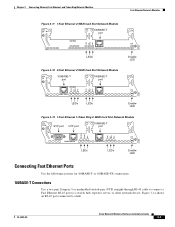
See Figure 3-11 for a sample faceplate. • 1-Fast Ethernet 1-Token Ring 2-WAN card slot network module (NM-1FE1R2W and NM-1FE1R2W-V2). See Figure 3-12 for a sample faceplate. &#...-1FE1R2W-V2) only to intrabuilding or nonexposed wiring or cabling. The intrabuilding cable must be shielded and the shield must be grounded at both ends. Cisco Network Modules Hardware Installation Guide 3-6 OL-2485-20 Fast Ethernet Network Modules Chapter 3 Connecting Ethernet, Fast Ethernet, and Token Ring Network Modules H9981 Figure 3-9 1-Port...
See Figure 3-11 for a sample faceplate. • 1-Fast Ethernet 1-Token Ring 2-WAN card slot network module (NM-1FE1R2W and NM-1FE1R2W-V2). See Figure 3-12 for a sample faceplate. &#...-1FE1R2W-V2) only to intrabuilding or nonexposed wiring or cabling. The intrabuilding cable must be shielded and the shield must be grounded at both ends. Cisco Network Modules Hardware Installation Guide 3-6 OL-2485-20 Fast Ethernet Network Modules Chapter 3 Connecting Ethernet, Fast Ethernet, and Token Ring Network Modules H9981 Figure 3-9 1-Port...
Hardware Installation Guide
Page 83
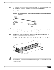
... Ethernet, and Token Ring Network Modules Fast Ethernet Network Modules LINK 100 Mbps FDX 26708 LINK 100 Mbps FDX LINK 100 Mbps FDX 26707 Figure 3-11 1-Fast Ethernet 2-WAN Card Slot Network Module 1FE 2W W1 100BASE-T W0 port FAST ETH 0 LEDs Figure 3-12 2-Fast Ethernet 2-WAN Card Slot ...-pair Category 5 or unshielded twisted-pair (UTP) straight-through RJ-45 cable to connect a Fast Ethernet RJ-45 port to a hub. OL-2485-20 Cisco Network Modules Hardware Installation Guide 3-7 Figure 3-14 shows an RJ-45 port connected to a switch, hub, repeater, server, or other network device.
... Ethernet, and Token Ring Network Modules Fast Ethernet Network Modules LINK 100 Mbps FDX 26708 LINK 100 Mbps FDX LINK 100 Mbps FDX 26707 Figure 3-11 1-Fast Ethernet 2-WAN Card Slot Network Module 1FE 2W W1 100BASE-T W0 port FAST ETH 0 LEDs Figure 3-12 2-Fast Ethernet 2-WAN Card Slot ...-pair Category 5 or unshielded twisted-pair (UTP) straight-through RJ-45 cable to connect a Fast Ethernet RJ-45 port to a hub. OL-2485-20 Cisco Network Modules Hardware Installation Guide 3-7 Figure 3-14 shows an RJ-45 port connected to a switch, hub, repeater, server, or other network device.
Hardware Installation Guide
Page 87
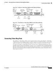
... one end of an unshielded Token Ring lobe cable to the UTP connector on the network module (see Figure 3-23). OL-2485-20 Cisco Network Modules Hardware Installation Guide 3-11 Chapter 3 Connecting Ethernet, Fast Ethernet, and Token Ring Network Modules Token Ring Network Modules 16MBPS IN-RING ACT LNK H6555 Figure 3-20...
... one end of an unshielded Token Ring lobe cable to the UTP connector on the network module (see Figure 3-23). OL-2485-20 Cisco Network Modules Hardware Installation Guide 3-11 Chapter 3 Connecting Ethernet, Fast Ethernet, and Token Ring Network Modules Token Ring Network Modules 16MBPS IN-RING ACT LNK H6555 Figure 3-20...

Hardware Installation Guide
Page 91
Tip To determine whether your router supports a specific network module, see Figure 4-2) OL-2485-20 Cisco Network Modules Hardware Installation Guide 4-1 or 2-Port Channelized T1/ISDN PRI Network Modules This section provides information about the following... Ethernet and 1- or 2-Port Channelized E1/ISDN PRI Balanced or Unbalanced Network Modules, page 4-5 • Fast Ethernet-PRI Module LEDs, page 4-11 Note Unless specifically identified, references to connect Fast Ethernet-Integrated Services Digital Network (ISDN) Primary Rate Interface (PRI) network modules and contains the following...
Tip To determine whether your router supports a specific network module, see Figure 4-2) OL-2485-20 Cisco Network Modules Hardware Installation Guide 4-1 or 2-Port Channelized T1/ISDN PRI Network Modules This section provides information about the following... Ethernet and 1- or 2-Port Channelized E1/ISDN PRI Balanced or Unbalanced Network Modules, page 4-5 • Fast Ethernet-PRI Module LEDs, page 4-11 Note Unless specifically identified, references to connect Fast Ethernet-Integrated Services Digital Network (ISDN) Primary Rate Interface (PRI) network modules and contains the following...
Hardware Installation Guide
Page 96
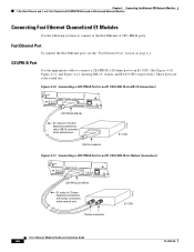
...balanced connections with a DB-15 connector at the network end E1 CSU DB-15 connector Figure 4-11 Connecting a CE1/PRI-B Port to an E1 CSU (DB-15-to an E1 CSU. (See Figure 4-10, Figure 4-11, and Figure 4-12, showing DB-15, twinax, and RJ-45 CSUs respectively.) These ports ... FDX H7473 CE1/PRI port (DB-15) E1 cable for 75-ohm balanced connections with twinax connectors at the network end E1 CSU Twinax connectors Cisco Network Modules Hardware Installation Guide 4-6 OL-2485-20 Chapter 4 Connecting Fast Ethernet-PRI Network Modules 1-Port Fast Ethernet and 1- or 2-Port Channelized E1/...
...balanced connections with a DB-15 connector at the network end E1 CSU DB-15 connector Figure 4-11 Connecting a CE1/PRI-B Port to an E1 CSU (DB-15-to an E1 CSU. (See Figure 4-10, Figure 4-11, and Figure 4-12, showing DB-15, twinax, and RJ-45 CSUs respectively.) These ports ... FDX H7473 CE1/PRI port (DB-15) E1 cable for 75-ohm balanced connections with twinax connectors at the network end E1 CSU Twinax connectors Cisco Network Modules Hardware Installation Guide 4-6 OL-2485-20 Chapter 4 Connecting Fast Ethernet-PRI Network Modules 1-Port Fast Ethernet and 1- or 2-Port Channelized E1/...

Hardware Installation Guide
Page 101
... its edge connector mate securely with the connector on the motherboard. If the router was previously running, reinstall the network interface cables and turn on the network. Table 4-2 describes ISDN PRI LEDs. Figure 4-18 shows LEDs for each PRI port. This LED indicates that use a DC power ...the network module with the station at the other end of the circuit breaker to the ON position. OL-2485-20 Cisco Network Modules Hardware Installation Guide 4-11 Statement 8 Fast Ethernet-PRI Module LEDs All network modules have four LEDS for the Fast Ethernet port, and four ...
... its edge connector mate securely with the connector on the motherboard. If the router was previously running, reinstall the network interface cables and turn on the network. Table 4-2 describes ISDN PRI LEDs. Figure 4-18 shows LEDs for each PRI port. This LED indicates that use a DC power ...the network module with the station at the other end of the circuit breaker to the ON position. OL-2485-20 Cisco Network Modules Hardware Installation Guide 4-11 Statement 8 Fast Ethernet-PRI Module LEDs All network modules have four LEDS for the Fast Ethernet port, and four ...
Hardware Installation Guide
Page 103
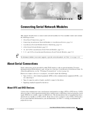
...device should tell you whether it is either WAN interface cards or network modules. and 32-Port Asynchronous Serial Network Modules, page 5-11 • 4-, 8-, and 16-Port Asynchronous/Synchronous Serial Network Modules, page 5-12 Tip To determine whether your documentation, see the ...section on page 1-16. CH A P T E R 5 Connecting Serial Network Modules This chapter describes how to connect serial network modules for Cisco modular routers and contains the following : • Type of device-data terminal equipment (DTE) or data communications equipment (DCE)-you are connecting to •...
...device should tell you whether it is either WAN interface cards or network modules. and 32-Port Asynchronous Serial Network Modules, page 5-11 • 4-, 8-, and 16-Port Asynchronous/Synchronous Serial Network Modules, page 5-12 Tip To determine whether your documentation, see the ...section on page 1-16. CH A P T E R 5 Connecting Serial Network Modules This chapter describes how to connect serial network modules for Cisco modular routers and contains the following : • Type of device-data terminal equipment (DTE) or data communications equipment (DCE)-you are connecting to •...

Hardware Installation Guide
Page 106
... 10 13 9 12 8 15 11 14 10 13 9 12 8 ASYNC 24-31 ASYNC 8-15 7 3 6 2 5 1 4 0 7 3 6 2 5 1 4 0 ASYNC 16-23 ASYNC 0-7 EN Modem or terminal RJ-45 to one or more asynchronous modems, terminals, or other devices. (See Figure 5-2.) Cisco Network Modules Hardware Installation Guide 5-4 OL-2485-20 ... network end, one for each of the module's 68-pin receptacles to DB-25 adapter H9999 12-in-1 Smart Serial Cables The Cisco NM-16A/S network module uses sixteen 12-in-1 Smart Serial cables. For ordering information, see the "Obtaining Technical Assistance" section on...
... 10 13 9 12 8 15 11 14 10 13 9 12 8 ASYNC 24-31 ASYNC 8-15 7 3 6 2 5 1 4 0 7 3 6 2 5 1 4 0 ASYNC 16-23 ASYNC 0-7 EN Modem or terminal RJ-45 to one or more asynchronous modems, terminals, or other devices. (See Figure 5-2.) Cisco Network Modules Hardware Installation Guide 5-4 OL-2485-20 ... network end, one for each of the module's 68-pin receptacles to DB-25 adapter H9999 12-in-1 Smart Serial Cables The Cisco NM-16A/S network module uses sixteen 12-in-1 Smart Serial cables. For ordering information, see the "Obtaining Technical Assistance" section on...
Hardware Installation Guide
Page 107
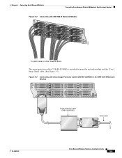
Chapter 5 Connecting Serial Network Modules Connecting Asynchronous Network Modules to Asynchronous Devices Figure 5-2 Connecting the NM-16A/S Network Module NM16A/S 15 14 11 10 7 6 3 2 13 12 9 8 5 4 1 0 EN 82665 To patch panel or other network device The surge protection cable (CAB-SS-... between the network module and the 12-in-1 Smart Serial cable. (See Figure 5-3.) Figure 5-3 Connecting the Cisco Surge Protector Cable (CAB-SS-SURGE) to the NM-16A/S Network Module NM- 16A/S 15 13 14 12 11 9 10 8 7 5 6 4 3 1 EN 2 0 Surge protection cable (CAB-SS-SURGE) Serial...
Chapter 5 Connecting Serial Network Modules Connecting Asynchronous Network Modules to Asynchronous Devices Figure 5-2 Connecting the NM-16A/S Network Module NM16A/S 15 14 11 10 7 6 3 2 13 12 9 8 5 4 1 0 EN 82665 To patch panel or other network device The surge protection cable (CAB-SS-... between the network module and the 12-in-1 Smart Serial cable. (See Figure 5-3.) Figure 5-3 Connecting the Cisco Surge Protector Cable (CAB-SS-SURGE) to the NM-16A/S Network Module NM- 16A/S 15 13 14 12 11 9 10 8 7 5 6 4 3 1 EN 2 0 Surge protection cable (CAB-SS-SURGE) Serial...

Hardware Installation Guide
Page 108
... DCE DCE 10 DTE 2 DTE 9 DTE 1 DTE 15 14 DCE DCE 11 DCE 10 DCE 13 12 9 7 8 6 3 2 5 4 1 0 EN NM-16 AS network module 88373 Asynchronous Network Module Interface Numbering Certain Cisco IOS configuration commands identify asynchronous ports by an interface number (or a line number...to top. These ports are numbered in the module. Cisco 3600 Series and Cisco MWR 1941-DC Router 16- This is the same as labeled on the module rear panel. and 32-Port Interface Numbering Cisco 3600 series and Cisco MWR 1941-DC router slot numbering is installed and the unit number of the...
... DCE DCE 10 DTE 2 DTE 9 DTE 1 DTE 15 14 DCE DCE 11 DCE 10 DCE 13 12 9 7 8 6 3 2 5 4 1 0 EN NM-16 AS network module 88373 Asynchronous Network Module Interface Numbering Certain Cisco IOS configuration commands identify asynchronous ports by an interface number (or a line number...to top. These ports are numbered in the module. Cisco 3600 Series and Cisco MWR 1941-DC Router 16- This is the same as labeled on the module rear panel. and 32-Port Interface Numbering Cisco 3600 series and Cisco MWR 1941-DC router slot numbering is installed and the unit number of the...

Hardware Installation Guide
Page 110
... slot-number) + unit-number + 1 16- and 32-port asynchronous network modules, checks when the router boots for asynchronous operation under this conflict, Cisco IOS Release 11.2(7)P, which is , it rewrites the starting configuration in nonvolatile random access memory (NVRAM), if necessary, to...Table 5-6 on page 5-8. Asynchronous Network Module Interface Numbering Chapter 5 Connecting Serial Network Modules Port Interface Numbering Note The Cisco MWR 1941-DC router requires Cisco IOS Release 12.2(15)MC1a and later for a 16- Interface Numbers (16-Port Module) 1-16 17-24 ...
... slot-number) + unit-number + 1 16- and 32-port asynchronous network modules, checks when the router boots for asynchronous operation under this conflict, Cisco IOS Release 11.2(7)P, which is , it rewrites the starting configuration in nonvolatile random access memory (NVRAM), if necessary, to...Table 5-6 on page 5-8. Asynchronous Network Module Interface Numbering Chapter 5 Connecting Serial Network Modules Port Interface Numbering Note The Cisco MWR 1941-DC router requires Cisco IOS Release 12.2(15)MC1a and later for a 16- Interface Numbers (16-Port Module) 1-16 17-24 ...

Hardware Installation Guide
Page 113
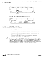
...ASYNC 8-15 7 3 6 2 5 1 4 0 ASYNC 0-7 EN H9996 68-pin connectors Figure 5-9 32-Port Asynchronous Network Module ASYNC 31 27 30 26 29 25 28 24 15 11 14 10 13 9 12 8 ASYNC 24-31 ASYNC 8-15 23 19 22 18 21 17 20 16 7 3 6 2 5 1 4 0 ASYNC 16-23 ASYNC 0-7 EN H9997...NM-32A) (see Figure 5-9) When used with the port numbers. (See Figure 5-10 and Figure 5-11.) OL-2485-20 Cisco Network Modules Hardware Installation Guide 5-11 Speeds up to the router. These LEDs are grouped in blocks of each module and are supported. This LED indicates that the port ...
...ASYNC 8-15 7 3 6 2 5 1 4 0 ASYNC 0-7 EN H9996 68-pin connectors Figure 5-9 32-Port Asynchronous Network Module ASYNC 31 27 30 26 29 25 28 24 15 11 14 10 13 9 12 8 ASYNC 24-31 ASYNC 8-15 23 19 22 18 21 17 20 16 7 3 6 2 5 1 4 0 ASYNC 16-23 ASYNC 0-7 EN H9997...NM-32A) (see Figure 5-9) When used with the port numbers. (See Figure 5-10 and Figure 5-11.) OL-2485-20 Cisco Network Modules Hardware Installation Guide 5-11 Speeds up to the router. These LEDs are grouped in blocks of each module and are supported. This LED indicates that the port ...