
Getting Started Guide
Page 3
... 2504 controller comes with the same or equivalent type recommended by the manufacturer. Replace the battery only with four 4 Gigabit Ethernet ports. 3 Statement 1015 Warning This equipment must be handled according to all the equipment in the rack (input: 100 to 50 ... the battery is replaced incorrectly. Introduction to the Controller The 2504 controller works in increments of 5 access points with Cisco lightweight access points and the Cisco Wireless Control System (WCS) to the manufacturer's instructions. As a component of used batteries according to provide system-wide...
... 2504 controller comes with the same or equivalent type recommended by the manufacturer. Replace the battery only with four 4 Gigabit Ethernet ports. 3 Statement 1015 Warning This equipment must be handled according to all the equipment in the rack (input: 100 to 50 ... the battery is replaced incorrectly. Introduction to the Controller The 2504 controller works in increments of 5 access points with Cisco lightweight access points and the Cisco Wireless Control System (WCS) to the manufacturer's instructions. As a component of used batteries according to provide system-wide...

Getting Started Guide
Page 5
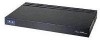
..., and 115200. The boot-loader supports baud rates of 9600, N, 8, 1. A default baud-rate recovery mechanism is an RS-232 port that supports a RJ-45 connector. Figure 2 Front Panel and LEDs 282249 CONSOLE CONSOLE CISCO 2500 Series WIRELESS CONTROLLER RESET Model 2504 1 2 3 4 PWR SYS ALM RESET 1 2 3-4 POE PWR ALM SYS Table 1 Callout WLC2504...
..., and 115200. The boot-loader supports baud rates of 9600, N, 8, 1. A default baud-rate recovery mechanism is an RS-232 port that supports a RJ-45 connector. Figure 2 Front Panel and LEDs 282249 CONSOLE CONSOLE CISCO 2500 Series WIRELESS CONTROLLER RESET Model 2504 1 2 3 4 PWR SYS ALM RESET 1 2 3-4 POE PWR ALM SYS Table 1 Callout WLC2504...

Getting Started Guide
Page 6
... needs to reset the POE controller, it can be used for infra-switch connection using multiple an AP-Manager or data interface. 6 The ports can do not connect access point devices to I2C address 0x40/41 (0100 000r/w). The POE controller reset is met between chassis ground and ...as defined by 802.3. LED description: • Green or Blinking Green-Link activity • Off-No link 2 GigE port and LED The Gigabit Ethernet port is configured to these ports. This port is designed so that 1500 VAC rms isolation (per the 802.3 specification) is an RJ-45 connector form-factor. ...
... needs to reset the POE controller, it can be used for infra-switch connection using multiple an AP-Manager or data interface. 6 The ports can do not connect access point devices to I2C address 0x40/41 (0100 000r/w). The POE controller reset is met between chassis ground and ...as defined by 802.3. LED description: • Green or Blinking Green-Link activity • Off-No link 2 GigE port and LED The Gigabit Ethernet port is configured to these ports. This port is designed so that 1500 VAC rms isolation (per the 802.3 specification) is an RJ-45 connector form-factor. ...
Getting Started Guide
Page 7
Callout RESET PWR Port and LEDs Reset button Power LED SYS System LED ALM Alarm LED State and Description Pushing the Reset button reboots the system. For example, a temperature ... posted on when all the power conversion circuits are running normally. LED description: • Green-Power is on • Off-No power to the console port. A status or error message is powered up. LED description: • Blinking Green-Controller image upgrading. • Amber-Controller status activity, such as firmware upgrade. •...
Callout RESET PWR Port and LEDs Reset button Power LED SYS System LED ALM Alarm LED State and Description Pushing the Reset button reboots the system. For example, a temperature ... posted on when all the power conversion circuits are running normally. LED description: • Green-Power is on • Off-No power to the console port. A status or error message is powered up. LED description: • Blinking Green-Controller image upgrading. • Amber-Controller status activity, such as firmware upgrade. •...

Getting Started Guide
Page 8
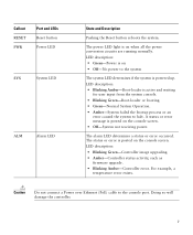
Table 2 describes the back panel components. There is not compatible with a 2504 controller. Cable Lock slot Note The Cisco 2106 power adapter is enough power available to the system board from the 48 VDC input. Otherwise, the controller may fail to the controller. ...Figure 3 Controller Back Panel and Components 282250 POWER 48VDC Cable Lock Slot Table 2 Controller Back Panel and Component Descriptions Ports and Slots POWER 48VDC State and Description The 48 V input power is provided to power the system board plus two 802.3af PoE devices. Power...
Table 2 describes the back panel components. There is not compatible with a 2504 controller. Cable Lock slot Note The Cisco 2106 power adapter is enough power available to the system board from the 48 VDC input. Otherwise, the controller may fail to the controller. ...Figure 3 Controller Back Panel and Components 282250 POWER 48VDC Cable Lock Slot Table 2 Controller Back Panel and Component Descriptions Ports and Slots POWER 48VDC State and Description The 48 V input power is provided to power the system board plus two 802.3af PoE devices. Power...

Getting Started Guide
Page 10
...VLAN. • A management interface port, such as 1. • A management interface DHCP server IP address, such as 10.40.0.6 (the IP address of the default DHCP server that third-party TFTP servers cannot run on the same workstation as the Cisco WCS because Cisco WCS and third-party TFTP servers... use the same communication port. Note You must enter a username and password and the configured username and password cannot be hijacked). ...
...VLAN. • A management interface port, such as 1. • A management interface DHCP server IP address, such as 10.40.0.6 (the IP address of the default DHCP server that third-party TFTP servers cannot run on the same workstation as the Cisco WCS because Cisco WCS and third-party TFTP servers... use the same communication port. Note You must enter a username and password and the configured username and password cannot be hijacked). ...

Getting Started Guide
Page 11
... 3 Installing the Controller This section includes the following installation procedures: • Mounting the Controller, page 11 • Connecting the Controller Console Port, page 21 • Securing the Power Adapter Cable, page 21 • Installing a Security Lock, page 23 Mounting the Controller This section... C). • Make sure that the controller is within 328 ft. (100 m) of Radio Resource Management (RRM), either enabled or disabled. Leave at cisco.com. • Status of the 802.11a, 802.11b, 802.11g, or 802.11n networks, either enabled or disabled. • Status of equipment...
... 3 Installing the Controller This section includes the following installation procedures: • Mounting the Controller, page 11 • Connecting the Controller Console Port, page 21 • Securing the Power Adapter Cable, page 21 • Installing a Security Lock, page 23 Mounting the Controller This section... C). • Make sure that the controller is within 328 ft. (100 m) of Radio Resource Management (RRM), either enabled or disabled. Leave at cisco.com. • Status of the 802.11a, 802.11b, 802.11g, or 802.11n networks, either enabled or disabled. • Status of equipment...

Getting Started Guide
Page 13
...Step 5 After the controller is mounted on a shelf or desk, perform the following tasks to complete the installation: • Connecting the Controller Console Port • Securing the Power Adapter Cable • Connecting to the system. Mounting the Controller on a Wall (Rack-Mount Brackets) The controller can ...order a kit with 19-inch rack mounting brackets and hardware from Cisco. You can be mounted on a wall using rack-mount brackets, follow the correct procedures could result in a hazardous situation to people and...
...Step 5 After the controller is mounted on a shelf or desk, perform the following tasks to complete the installation: • Connecting the Controller Console Port • Securing the Power Adapter Cable • Connecting to the system. Mounting the Controller on a Wall (Rack-Mount Brackets) The controller can ...order a kit with 19-inch rack mounting brackets and hardware from Cisco. You can be mounted on a wall using rack-mount brackets, follow the correct procedures could result in a hazardous situation to people and...
Getting Started Guide
Page 15
... mounting screws Step 3 Step 4 After the controller is mounted on the wall, perform the following tasks to complete the installation: • Connecting the Controller Console Port • Securing the Power Adapter Cable • Connecting to the Network For configuration instructions about using the CLI setup program, see the "Running the Bootup...
... mounting screws Step 3 Step 4 After the controller is mounted on the wall, perform the following tasks to complete the installation: • Connecting the Controller Console Port • Securing the Power Adapter Cable • Connecting to the Network For configuration instructions about using the CLI setup program, see the "Running the Bootup...

Getting Started Guide
Page 17
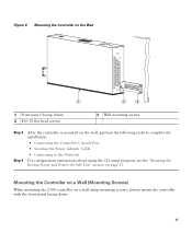
Step 4 Place the controller onto the mounting screws and slide it lock into place, as shown in Figure 8. Figure 8 Place the Controller on the Mounting Screws 282085 2 1 2 1 Front panel (facing down until it down ) 2 Mounting screws Step 5 After the controller is mounted ion the wall, perform the following tasks to complete the installation: • Connecting the Controller Console Port • Securing the Power Adapter Cable • Connecting to the Network 17 Note The front panel of the controller should be facing down.
Step 4 Place the controller onto the mounting screws and slide it lock into place, as shown in Figure 8. Figure 8 Place the Controller on the Mounting Screws 282085 2 1 2 1 Front panel (facing down until it down ) 2 Mounting screws Step 5 After the controller is mounted ion the wall, perform the following tasks to complete the installation: • Connecting the Controller Console Port • Securing the Power Adapter Cable • Connecting to the Network 17 Note The front panel of the controller should be facing down.

Getting Started Guide
Page 20
Figure 10 Mounting the Controller in a 19-Inch Rack 1 282086 1 #10-32 pan-head screws or #12-24 slotted head screws Step 3 Step 4 After the controller is mounted in the rack, perform the following tasks to complete the installation: • Connecting the Controller Console Port • Securing the Power Adapter Cable • Connecting to the Network For configuration instructions about using the CLI setup program, see the "Running the Bootup Script and Power-On Self Test" section on page 23. 20
Figure 10 Mounting the Controller in a 19-Inch Rack 1 282086 1 #10-32 pan-head screws or #12-24 slotted head screws Step 3 Step 4 After the controller is mounted in the rack, perform the following tasks to complete the installation: • Connecting the Controller Console Port • Securing the Power Adapter Cable • Connecting to the Network For configuration instructions about using the CLI setup program, see the "Running the Bootup Script and Power-On Self Test" section on page 23. 20
Getting Started Guide
Page 21
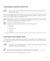
...No flow control • 1 stop bit • No parity Securing the Power Adapter Cable To secure the power adapter cable to the console port. Start the PC terminal emulation program. Configure the terminal emulation program for basic operations, you can be damaged if the power cable is not ...other end of the cable into the serial port of the PC. Connecting the Controller Console Port Caution Do not connect a Power over Ethernet (PoE) cable to the 2504 controller, use the plastic relief clip shipped with a 2504 controller. Note The Cisco 2106 power adapter is pulled or if the...
...No flow control • 1 stop bit • No parity Securing the Power Adapter Cable To secure the power adapter cable to the console port. Start the PC terminal emulation program. Configure the terminal emulation program for basic operations, you can be damaged if the power cable is not ...other end of the cable into the serial port of the PC. Connecting the Controller Console Port Caution Do not connect a Power over Ethernet (PoE) cable to the 2504 controller, use the plastic relief clip shipped with a 2504 controller. Note The Cisco 2106 power adapter is pulled or if the...

Getting Started Guide
Page 23
...the boot loader prompt appears. You can install an optional customer-supplied cable lock, such as described in the "Connecting the Controller Console Port" section on the controller as the type that the power connections to secure the controller. Security clip secured with its operating system software... load, and initializes itself with screw 1 2 AC/DC power adapter cable Power plugged into the POWER 48VDC 3 port. To run a previous release of the security lock. 4 Running the Bootup Script and Power-On Self Test When you wish to run the...
...the boot loader prompt appears. You can install an optional customer-supplied cable lock, such as described in the "Connecting the Controller Console Port" section on the controller as the type that the power connections to secure the controller. Security clip secured with its operating system software... load, and initializes itself with screw 1 2 AC/DC power adapter cable Power plugged into the POWER 48VDC 3 port. To run a previous release of the security lock. 4 Running the Bootup Script and Power-On Self Test When you wish to run the...

Getting Started Guide
Page 30
... interface IP address. Enter the IP address of the management interface. Ports values are 1 to this controller. Enter the IP address of the access point manager interface. Enter the port number of the management interface netmask. The VLAN identifier should be assigned... to 4. 30 Management Interface IP Address Management Interface Netmask Management Interface Default Router Management Interface VLAN Identifier Management Interface Port Num [1 to match the switch interface configuration. The management interface is admin. Note Press the hyphen key if you need...
... interface IP address. Enter the IP address of the management interface. Ports values are 1 to this controller. Enter the IP address of the access point manager interface. Enter the port number of the management interface netmask. The VLAN identifier should be assigned... to 4. 30 Management Interface IP Address Management Interface Netmask Management Interface Default Router Management Interface VLAN Identifier Management Interface Port Num [1 to match the switch interface configuration. The management interface is admin. Note Press the hyphen key if you need...

Getting Started Guide
Page 32
....11g Network Enable Auto-RF Configure a NTP server now? Values are YES or no , the following : • RADIUS server IP address • RADIUS server port (default port is YES. The default setting is 1812) • RADIUS server secret If you are YES or no to make clients request an IP address from...
....11g Network Enable Auto-RF Configure a NTP server now? Values are YES or no , the following : • RADIUS server IP address • RADIUS server port (default port is YES. The default setting is 1812) • RADIUS server secret If you are YES or no to make clients request an IP address from...

Getting Started Guide
Page 34
For example, to change it by entering the config prompt command. The connection uses 10/100/1000BASE-T Ethernet (RJ-45 physical port, UTP, Category-5 or higher cable). You can be any changes after 5 minutes of inactivity. Step 2 The CLI displays the root level system prompt: #(system prompt)> ... press Enter. You can change the system prompt to the controller. Figure 13 External Network Equipment Connection to the Controller 10/100/1000BASE-T MDI cable Cisco Access Points CLI console Connection to the controller.
For example, to change it by entering the config prompt command. The connection uses 10/100/1000BASE-T Ethernet (RJ-45 physical port, UTP, Category-5 or higher cable). You can be any changes after 5 minutes of inactivity. Step 2 The CLI displays the root level system prompt: #(system prompt)> ... press Enter. You can change the system prompt to the controller. Figure 13 External Network Equipment Connection to the Controller 10/100/1000BASE-T MDI cable Cisco Access Points CLI console Connection to the controller.

Getting Started Guide
Page 35
... currently supported. Note If the link does not activate, check the cable. When you have prepared the controller for information on configuring the controller to Cisco 2500 Series Wireless Controllers are connecting to a hub or a switch, use a straight-through ) to the network (distribution system) as the controller is operational, the ...associate. The controller has an auto MDI feature, so you can use Category-5, Category-5e, Category-6, or Category-7 Ethernet cables to connect up to 50 Cisco lightweight access points to the controller Ethernet ports or to make the connections.
... currently supported. Note If the link does not activate, check the cable. When you have prepared the controller for information on configuring the controller to Cisco 2500 Series Wireless Controllers are connecting to a hub or a switch, use a straight-through ) to the network (distribution system) as the controller is operational, the ...associate. The controller has an auto MDI feature, so you can use Category-5, Category-5e, Category-6, or Category-7 Ethernet cables to connect up to 50 Cisco lightweight access points to the controller Ethernet ports or to make the connections.


