

Getting Started Guide
Page 3
... lightweight access points in increments of 5 access points with Cisco lightweight access points and the Cisco Wireless Control System (WCS) to all the equipment in an equipment rack, be sure that suitable grounding is sufficiently rated to 240 VAC, 50-60 Hz, output: 80 W per controller). • Verify the integrity of the electrical ground before installing the controller. Replace the battery only with four 4 Gigabit Ethernet ports. 3 The 2504 controller...
... lightweight access points in increments of 5 access points with Cisco lightweight access points and the Cisco Wireless Control System (WCS) to all the equipment in an equipment rack, be sure that suitable grounding is sufficiently rated to 240 VAC, 50-60 Hz, output: 80 W per controller). • Verify the integrity of the electrical ground before installing the controller. Replace the battery only with four 4 Gigabit Ethernet ports. 3 The 2504 controller...

Getting Started Guide
Page 4
... a 2504 controller network topology and network connections, showing the medium dependent interface (MDI) Ethernet cables required. Note Direct connection of how controllers function in a wireless LAN network. Figure 1 Typical Controller Topology and Network Connections Console emulator for initial boot-up Null modem serial cable (DB-9 -> RJ-45) to console connection Cisco WCS software, web user interface 10/100/1000BASE-T MDI cable Network Distribution system connection LAN link for management software connections WAN or LAN connection to Cisco 2500 Series Wireless Controllers are...
... a 2504 controller network topology and network connections, showing the medium dependent interface (MDI) Ethernet cables required. Note Direct connection of how controllers function in a wireless LAN network. Figure 1 Typical Controller Topology and Network Connections Console emulator for initial boot-up Null modem serial cable (DB-9 -> RJ-45) to console connection Cisco WCS software, web user interface 10/100/1000BASE-T MDI cable Network Distribution system connection LAN link for management software connections WAN or LAN connection to Cisco 2500 Series Wireless Controllers are...

Getting Started Guide
Page 5
... Panel and LEDs 282249 CONSOLE CONSOLE CISCO 2500 Series WIRELESS CONTROLLER RESET Model 2504 1 2 3 4 PWR SYS ALM RESET 1 2 3-4 POE PWR ALM SYS Table 1 Callout WLC2504 Front Panel Component Descriptions Port and LEDs State and Description CONSOLE CPU console port The CPU console port is not available; A default baud-rate recovery mechanism is an RS-232 port that supports a RJ-45 connector. This is not a defect. Table 1 describes the components of the LED manufacturer's specifications and is within the normal range...
... Panel and LEDs 282249 CONSOLE CONSOLE CISCO 2500 Series WIRELESS CONTROLLER RESET Model 2504 1 2 3 4 PWR SYS ALM RESET 1 2 3-4 POE PWR ALM SYS Table 1 Callout WLC2504 Front Panel Component Descriptions Port and LEDs State and Description CONSOLE CPU console port The CPU console port is not available; A default baud-rate recovery mechanism is an RS-232 port that supports a RJ-45 connector. This is not a defect. Table 1 describes the components of the LED manufacturer's specifications and is within the normal range...

Getting Started Guide
Page 6
... I2C address 0x40/41 (0100 000r/w). Callout Port and LEDs State and Description 1 GigE port and LED The Gigabit Ethernet port is driven from system reset. The POE controller is an RJ-45 connector form-factor. LED description: • Green or Blinking Green-Link activity • Off-No link 2 GigE port and LED The Gigabit Ethernet port is configured to reset the POE controller, it can be used for infra-switch connection using multiple an AP-Manager or data interface. 6 LED description: • Green or Blinking Green-Link...
... I2C address 0x40/41 (0100 000r/w). Callout Port and LEDs State and Description 1 GigE port and LED The Gigabit Ethernet port is driven from system reset. The POE controller is an RJ-45 connector form-factor. LED description: • Green or Blinking Green-Link activity • Off-No link 2 GigE port and LED The Gigabit Ethernet port is configured to reset the POE controller, it can be used for infra-switch connection using multiple an AP-Manager or data interface. 6 LED description: • Green or Blinking Green-Link...

Getting Started Guide
Page 9
... following tools and information before you can install the controller: • Wireless controller hardware - Required Tools and Information You will need the following items: • One Cisco 2504 Wireless Controller. • One Power supply and power cord (power cord option configurable). • Cisco 2504 Wireless Controller software pre-loaded on the controller (software option configurable). • Optional licenses will be included, if selected. Null modem serial cable to connect CLI console and controller 9 Controller with factory-supplied power cord and mounting hardware -
... following tools and information before you can install the controller: • Wireless controller hardware - Required Tools and Information You will need the following items: • One Cisco 2504 Wireless Controller. • One Power supply and power cord (power cord option configurable). • Cisco 2504 Wireless Controller software pre-loaded on the controller (software option configurable). • Optional licenses will be included, if selected. Null modem serial cable to connect CLI console and controller 9 Controller with factory-supplied power cord and mounting hardware -

Getting Started Guide
Page 10
... to clients and the management interface. • A virtual gateway IP address (a fictitious, unassigned IP address, such as 1.1.1.1, used by all Cisco wireless controller Layer 3 security and mobility managers). • A Cisco wireless controller mobility or RF group name, such as the Cisco WCS because Cisco WCS and third-party TFTP servers use the same communication port. No is assigned to allow static IP addresses from your wireless LAN or network administrator: • A system (controller name), such as wlan1. Cisco uses an integral TFTP server...
... to clients and the management interface. • A virtual gateway IP address (a fictitious, unassigned IP address, such as 1.1.1.1, used by all Cisco wireless controller Layer 3 security and mobility managers). • A Cisco wireless controller mobility or RF group name, such as the Cisco WCS because Cisco WCS and third-party TFTP servers use the same communication port. No is assigned to allow static IP addresses from your wireless LAN or network administrator: • A system (controller name), such as wlan1. Cisco uses an integral TFTP server...

Getting Started Guide
Page 11
... Controller Console Port, page 21 • Securing the Power Adapter Cable, page 21 • Installing a Security Lock, page 23 Mounting the Controller This section includes the following these guidelines: • Make sure you can reach the controller and all cables attached to the Cisco Wireless LAN Controller Configuration Guide for this installation. • RADIUS server IP address, communications port, and secret if you install it . • Make sure that water or excessive moisture cannot get...
... Controller Console Port, page 21 • Securing the Power Adapter Cable, page 21 • Installing a Security Lock, page 23 Mounting the Controller This section includes the following these guidelines: • Make sure you can reach the controller and all cables attached to the Cisco Wireless LAN Controller Configuration Guide for this installation. • RADIUS server IP address, communications port, and secret if you install it . • Make sure that water or excessive moisture cannot get...

Getting Started Guide
Page 13
... table or shelf near an AC power source. Step 3 Place the switch on a wall using rack-mount brackets, follow these steps: Step 1 Attach the 19-inch brackets to each side of space around the controller ventilation openings to the Network For configuration instructions about using the CLI setup program, see the "Running the Bootup Script and Power-On Self Test" section on a wall using an optional rack-mount bracket kit...
... table or shelf near an AC power source. Step 3 Place the switch on a wall using rack-mount brackets, follow these steps: Step 1 Attach the 19-inch brackets to each side of space around the controller ventilation openings to the Network For configuration instructions about using the CLI setup program, see the "Running the Bootup Script and Power-On Self Test" section on a wall using an optional rack-mount bracket kit...
Getting Started Guide
Page 15
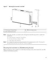
Mounting the Controller on a Wall (Mounting Screws) When mounting the 2504 controller on a wall using the CLI setup program, see the "Running the Bootup Script and Power-On Self Test" section on the wall, perform the following tasks to complete the installation: • Connecting the Controller Console Port • Securing the Power Adapter Cable • Connecting to the Network For configuration instructions about using mounting screws, always mount the controller with the front panel facing down. 15 Figure 6 Mounting the...
Mounting the Controller on a Wall (Mounting Screws) When mounting the 2504 controller on a wall using the CLI setup program, see the "Running the Bootup Script and Power-On Self Test" section on the wall, perform the following tasks to complete the installation: • Connecting the Controller Console Port • Securing the Power Adapter Cable • Connecting to the Network For configuration instructions about using mounting screws, always mount the controller with the front panel facing down. 15 Figure 6 Mounting the...

Getting Started Guide
Page 20
Figure 10 Mounting the Controller in a 19-Inch Rack 1 282086 1 #10-32 pan-head screws or #12-24 slotted head screws Step 3 Step 4 After the controller is mounted in the rack, perform the following tasks to complete the installation: • Connecting the Controller Console Port • Securing the Power Adapter Cable • Connecting to the Network For configuration instructions about using the CLI setup program, see the "Running the Bootup Script and Power-On Self Test" section on page 23. 20
Figure 10 Mounting the Controller in a 19-Inch Rack 1 282086 1 #10-32 pan-head screws or #12-24 slotted head screws Step 3 Step 4 After the controller is mounted in the rack, perform the following tasks to complete the installation: • Connecting the Controller Console Port • Securing the Power Adapter Cable • Connecting to the Network For configuration instructions about using the CLI setup program, see the "Running the Bootup Script and Power-On Self Test" section on page 23. 20

Getting Started Guide
Page 23
... green front panel Power LED lights. Note If you plug the controller into an AC power source, the bootup script initializes the system, verifies the hardware configuration, loads its microcode into memory, verifies its stored configurations. Refer to the CLI console on the controller as the type that is supplying power and that the electrical outlet is used to secure a laptop computer, to 240 VAC, 50-60 Hz electrical outlet. Installing a Security...
... green front panel Power LED lights. Note If you plug the controller into an AC power source, the bootup script initializes the system, verifies the hardware configuration, loads its microcode into memory, verifies its stored configurations. Refer to the CLI console on the controller as the type that is supplying power and that the electrical outlet is used to secure a laptop computer, to 240 VAC, 50-60 Hz electrical outlet. Installing a Security...

Getting Started Guide
Page 24
... user login prompt appears. Loading primary image (7.0.114.76) 100% 31427987 bytes read Launching images... done Network: octeth0', octeth1, octeth2, octeth3 ' - Type: Hard Disk - OCTEON CN5230C-SCP pass 2.0, Core clock: 750 MHz, DDR clock: 330 MHz (660 Mhz data rate) CPU Cores: 4 DRAM: 1024 MB Flash: 32 MB Clearing DRAM........ Active interface E - Format FLASH Drive 6. Step 3 Observe the bootup using the CLI screen. Clear configuration 5. Model...
... user login prompt appears. Loading primary image (7.0.114.76) 100% 31427987 bytes read Launching images... done Network: octeth0', octeth1, octeth2, octeth3 ' - Type: Hard Disk - OCTEON CN5230C-SCP pass 2.0, Core clock: 750 MHz, DDR clock: 330 MHz (660 Mhz data rate) CPU Cores: 4 DRAM: 1024 MB Flash: 32 MB Clearing DRAM........ Active interface E - Format FLASH Drive 6. Step 3 Observe the bootup using the CLI screen. Clear configuration 5. Model...

Getting Started Guide
Page 25
... Switching Services: ok Starting QoS Services: ok Starting Policy Manager: ok Starting Data Transport Link Layer: ok Starting Access Control List Services: ok Starting System Interfaces: ok Starting Client Troubleshooting Service: ok Starting Management Frame Protection: ok Starting Certificate Database: ok Starting VPN Services: ok Starting Licensing Services: ok Starting LWAPP: ok Starting CAPWAP: ok Starting LOCP: ok Starting Security Services: ok 25 Cisco AireOS Version 7.0.114.76 Firmware Version PIC 14.0 Initializing OS Services: ok Initializing Serial Services: ok Initializing Network...
... Switching Services: ok Starting QoS Services: ok Starting Policy Manager: ok Starting Data Transport Link Layer: ok Starting Access Control List Services: ok Starting System Interfaces: ok Starting Client Troubleshooting Service: ok Starting Management Frame Protection: ok Starting Certificate Database: ok Starting VPN Services: ok Starting Licensing Services: ok Starting LWAPP: ok Starting CAPWAP: ok Starting LOCP: ok Starting Security Services: ok 25 Cisco AireOS Version 7.0.114.76 Firmware Version PIC 14.0 Initializing OS Services: ok Initializing Serial Services: ok Initializing Network...

Getting Started Guide
Page 27
Format FLASH Drive 6. Loading primary image (7.0.114.76) 100% 31427987 bytes read Launching images... Active 2. Do not reboot the controller until the user login prompt appears. Software Copyright Cisco Systems, Inc. Installing ether-pow driver - 0x6008 starting pid 672, tty '': '/etc/init.d/rcS' type = block dump-device = 254:4 disrupt level = header compress = none ifconfig: SIOCGIFFLAGS: No such device Detecting Hardware ... XML config selected Validating XML configuration octeon_device_init: found 1 DPs...
Format FLASH Drive 6. Loading primary image (7.0.114.76) 100% 31427987 bytes read Launching images... Active 2. Do not reboot the controller until the user login prompt appears. Software Copyright Cisco Systems, Inc. Installing ether-pow driver - 0x6008 starting pid 672, tty '': '/etc/init.d/rcS' type = block dump-device = 254:4 disrupt level = header compress = none ifconfig: SIOCGIFFLAGS: No such device Detecting Hardware ... XML config selected Validating XML configuration octeon_device_init: found 1 DPs...

Getting Started Guide
Page 30
... can access the controller GUI interface using the management interface IP address. The default administrative username is no default administrative password, you want to assign to 24 ASCII characters for in-band management of the management interface netmask. You can enter up to the controller. Enter the port number of the management interface. Enter the administrative user name to be set to 4] Note There is admin. Enter the IP address of the access point manager interface. The VLAN...
... can access the controller GUI interface using the management interface IP address. The default administrative username is no default administrative password, you want to assign to 24 ASCII characters for in-band management of the management interface netmask. You can enter up to the controller. Enter the port number of the management interface. Enter the administrative user name to be set to 4] Note There is admin. Enter the IP address of the access point manager interface. The VLAN...

Getting Started Guide
Page 31
... Setting Action Management Interface DHCP Server IP Address Enter the management interface DHCP server IP address. All of the controller virtual interface. The following message appears: Warning! The virtual interface is the default SSID that you want the controller to configure DHCP Bridging Mode. The default WLAN security policy requires a RADIUS server. You should enter a fictitious, unassigned IP address, such as guest web authentication and VPN termination. Virtual Gateway IP Address Enter the IP address of the controllers in the same mobility group and...
... Setting Action Management Interface DHCP Server IP Address Enter the management interface DHCP server IP address. All of the controller virtual interface. The following message appears: Warning! The virtual interface is the default SSID that you want the controller to configure DHCP Bridging Mode. The default WLAN security policy requires a RADIUS server. You should enter a fictitious, unassigned IP address, such as guest web authentication and VPN termination. Virtual Gateway IP Address Enter the IP address of the controllers in the same mobility group and...

Getting Started Guide
Page 32
... Setting Allow Static IP Addresses Configure a RADIUS Server Now? Enter the NTP server IP address Action Enter YES to allow clients to assign their own IP address or no , the following : • RADIUS server IP address • RADIUS server port (default port is YES. The default WLAN security policy requires a RADIUS server. Enter YES to disable the 802.11a radio network. The values are YES or no to configure an NTP server. Enter Country Code List Enable...
... Setting Allow Static IP Addresses Configure a RADIUS Server Now? Enter the NTP server IP address Action Enter YES to allow clients to assign their own IP address or no , the following : • RADIUS server IP address • RADIUS server port (default port is YES. The default WLAN security policy requires a RADIUS server. Enter YES to disable the 802.11a radio network. The values are YES or no to configure an NTP server. Enter Country Code List Enable...

Getting Started Guide
Page 33
.... Values are case sensitive. 33 Note The administrative username and password you to log in. 5 Logging into the Controller To log into the 2504 controller, follow these steps: Step 1 Enter a valid username and password to log into the controller CLI. the controller saves your configuration, reboots, and prompts you created in the "Configure a NTP Server Now?" Table 3 Startup Wizard Information (continued) Wizard Setting Enter a polling interval between 3600 and 604800 secs...
.... Values are case sensitive. 33 Note The administrative username and password you to log in. 5 Logging into the Controller To log into the 2504 controller, follow these steps: Step 1 Enter a valid username and password to log into the controller CLI. the controller saves your configuration, reboots, and prompts you created in the "Configure a NTP Server Now?" Table 3 Startup Wizard Information (continued) Wizard Setting Enter a polling interval between 3600 and 604800 secs...

Getting Started Guide
Page 34
.... Note The CLI automatically logs out without saving any alphanumeric string up to change it by entering the config prompt command. Always use Category-5, Category-5e, Category-6, or Category-7 Ethernet cables to connect the office network equipment to main office Network 34 Firewall Office network 10/100/1000BASE-T MDI cable 282298 Figure 13 External Network Equipment Connection to the Controller 10/100/1000BASE-T MDI cable Cisco Access Points CLI console Connection to the controller. Make...
.... Note The CLI automatically logs out without saving any alphanumeric string up to change it by entering the config prompt command. Always use Category-5, Category-5e, Category-6, or Category-7 Ethernet cables to connect the office network equipment to main office Network 34 Firewall Office network 10/100/1000BASE-T MDI cable 282298 Figure 13 External Network Equipment Connection to the Controller 10/100/1000BASE-T MDI cable Cisco Access Points CLI console Connection to the controller. Make...

Getting Started Guide
Page 35
... controller has an auto MDI feature, so you can use a straight-through ) to associate. Refer to the Cisco Wireless LAN Controller Configuration Guide for information on configuring the controller to meet the specific needs of access points to Cisco 2500 Series Wireless Controllers are not currently supported. When it detects an access point, it records the access point MAC address in Figure 14. When you have prepared the controller for a controller. Note If the link does not activate, check the cable. Connecting Access Points...
... controller has an auto MDI feature, so you can use a straight-through ) to associate. Refer to the Cisco Wireless LAN Controller Configuration Guide for information on configuring the controller to meet the specific needs of access points to Cisco 2500 Series Wireless Controllers are not currently supported. When it detects an access point, it records the access point MAC address in Figure 14. When you have prepared the controller for a controller. Note If the link does not activate, check the cable. Connecting Access Points...


