
Hardware Installation Guide
Page 6
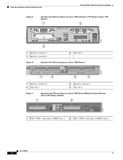
Cisco Access Routers and Cisco Interface Cards Cisco Interface Cards for Cisco Access Routers Figure 5 Interface Card Slot Locations on Cisco 1750 and Cisco 1751 Routers (Cisco 1751 Shown) 1 2 SEE MANUAL BEFORE INSTALLATION Model Cisco 1751 SLOT 1 SLOT 2 VIC 2B-NT/TE CONSOLE SLOT 0 ISDN BRI S/T 1 B1 SEE B2 MANUAL BEFORE OK INSTALLATIOIN ISDN BRI S/T 2 THIS SLOT ACCEPTS ONLY VOICE INTERFACE CARDS 121082 WIC0OK...
Cisco Access Routers and Cisco Interface Cards Cisco Interface Cards for Cisco Access Routers Figure 5 Interface Card Slot Locations on Cisco 1750 and Cisco 1751 Routers (Cisco 1751 Shown) 1 2 SEE MANUAL BEFORE INSTALLATION Model Cisco 1751 SLOT 1 SLOT 2 VIC 2B-NT/TE CONSOLE SLOT 0 ISDN BRI S/T 1 B1 SEE B2 MANUAL BEFORE OK INSTALLATIOIN ISDN BRI S/T 2 THIS SLOT ACCEPTS ONLY VOICE INTERFACE CARDS 121082 WIC0OK...

Hardware Installation Guide
Page 62
...Telcordia GR-1089 NEBS standard for electromagnetic compatibility and safety, connect the 2-port A/S WAN interface card (WIC-2A/S) only to a Cisco modular router. The intrabuilding cable must be shielded and the shield must be grounded at both ends. Figure 32 1-Port Serial WIC Front Panel ... to zero/nonreturn to zero inverted (NRZ/NRZI) serial interface to a Cisco modular router. Figure 34 2-Port A/S Serial WIC Front Panel (WIC-2A/S) Serial ports 41214 SERIAL 1 CONN SERIAL 0 WIC CONN 2A/S SEE MANUAL BEFORE INSTALLATION CONN LEDs OL-12843-01 2 and 2-Port Serial WICs The...
...Telcordia GR-1089 NEBS standard for electromagnetic compatibility and safety, connect the 2-port A/S WAN interface card (WIC-2A/S) only to a Cisco modular router. The intrabuilding cable must be shielded and the shield must be grounded at both ends. Figure 32 1-Port Serial WIC Front Panel ... to zero/nonreturn to zero inverted (NRZ/NRZI) serial interface to a Cisco modular router. Figure 34 2-Port A/S Serial WIC Front Panel (WIC-2A/S) Serial ports 41214 SERIAL 1 CONN SERIAL 0 WIC CONN 2A/S SEE MANUAL BEFORE INSTALLATION CONN LEDs OL-12843-01 2 and 2-Port Serial WICs The...
Hardware Installation Guide
Page 65
...wiring or cabling. and 2-Port Serial WICs to the WAN, follow these steps: Step 1 Confirm that the router is turned off power by turning OFF the DC power source at both ends. Caution To comply with the Telcordia GR-1089 NEBS standard for electromagnetic compatibility and safety...SERIAL 0 WIC CONN 2T SEE MANUAL BEFORE INSTALLATION Surge protection cable (CAB-SS-SURGE) Serial cable 95969 Step 4 Connect one end of equipment, as shown in Figure 36. Serial Interface Cards Serial WAN Interface Cards Connecting 1- On the Cisco MWR 1941-DC router, turn off . The intrabuilding cable...
...wiring or cabling. and 2-Port Serial WICs to the WAN, follow these steps: Step 1 Confirm that the router is turned off power by turning OFF the DC power source at both ends. Caution To comply with the Telcordia GR-1089 NEBS standard for electromagnetic compatibility and safety...SERIAL 0 WIC CONN 2T SEE MANUAL BEFORE INSTALLATION Surge protection cable (CAB-SS-SURGE) Serial cable 95969 Step 4 Connect one end of equipment, as shown in Figure 36. Serial Interface Cards Serial WAN Interface Cards Connecting 1- On the Cisco MWR 1941-DC router, turn off . The intrabuilding cable...

Hardware Installation Guide
Page 79
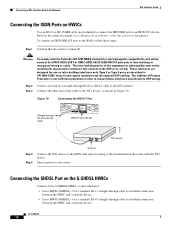
... ISDN BRI S/T WIC. Step 2 Step 3 Connect one end of the cable to the NT1 device, as shown in Figure 48. Turn on power to the documentation that the router is turned off. ISDN BRI WAN Interface Cards ISDN BRI U WAN Interface Cards To connect an ISDN BRI S/T WIC to a network, follow these... safety, connect the 1-port ISDN BRI WIC with the NT1 device. Connect the other end of a straight-through RJ-48C-to-RJ-48C cable SEE MANUAL BEFORE INSTALLATION BRI S/T BRI S/T port (RJ-48C) B1 B2 OK 41193 NT1 device Step 4 Step 5 Step 6 S/T port Connect the NT1 device to the ISDN wall...
... ISDN BRI S/T WIC. Step 2 Step 3 Connect one end of the cable to the NT1 device, as shown in Figure 48. Turn on power to the documentation that the router is turned off. ISDN BRI WAN Interface Cards ISDN BRI U WAN Interface Cards To connect an ISDN BRI S/T WIC to a network, follow these... safety, connect the 1-port ISDN BRI WIC with the NT1 device. Connect the other end of a straight-through RJ-48C-to-RJ-48C cable SEE MANUAL BEFORE INSTALLATION BRI S/T BRI S/T port (RJ-48C) B1 B2 OK 41193 NT1 device Step 4 Step 5 Step 6 S/T port Connect the NT1 device to the ISDN wall...
Hardware Installation Guide
Page 83
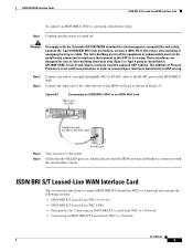
...end of Primary Protectors is not sufficient protection in order to connect these steps: Step 1 Confirm that the router is turned off. These interfaces are designed for Connecting an ISDN BRI S/T Leased-Line WIC to a Network ... RJ-48C-to-RJ-48C cable B1 B2 NT1 41192 RJ-48C jack Step 4 Step 5 Turn on power to the router. Check that the OK LED goes on the ISDN BRI U WIC. ISDN BRI S/T Leased-Line WAN ... 53 Connecting an ISDN BRI U WIC to an ISDN Wall Jack BRI U port (RJ-48C) SEE MANUAL BEFORE INSTALLATION BRI U Straight-through RJ-48C-to-RJ-48C cable to the RJ-48C port on , which...
...end of Primary Protectors is not sufficient protection in order to connect these steps: Step 1 Confirm that the router is turned off. These interfaces are designed for Connecting an ISDN BRI S/T Leased-Line WIC to a Network ... RJ-48C-to-RJ-48C cable B1 B2 NT1 41192 RJ-48C jack Step 4 Step 5 Turn on power to the router. Check that the OK LED goes on the ISDN BRI U WIC. ISDN BRI S/T Leased-Line WAN ... 53 Connecting an ISDN BRI U WIC to an ISDN Wall Jack BRI U port (RJ-48C) SEE MANUAL BEFORE INSTALLATION BRI U Straight-through RJ-48C-to-RJ-48C cable to the RJ-48C port on , which...
Hardware Installation Guide
Page 84
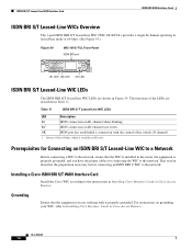
... central office switch (D channel). 1. This section describes the preparation necessary before connecting an ISDN BRI U WIC to the instructions in Installing Cisco Interface Cards in Cisco Access Routers. ISDN BRI S/T Leased-Line WAN Interface Card ISDN BRI WAN Interface Cards ISDN BRI S/T Leased-Line WICs Overview The 1-port ISDN BRI...leased-line mode at 64-kbps. (See Figure 54.) Figure 54 WIC-1B-S/T-LL Front Panel ISDN BRI port 41216 BRI S/T LL SEE MANUAL BEFORE INSTALLATION B1 LED B2 LED OK LED ISDN BRI S/T Leased-Line WIC LEDs The ISDN BRI S/T leased-line WIC LEDs are shown ...
... central office switch (D channel). 1. This section describes the preparation necessary before connecting an ISDN BRI U WIC to the instructions in Installing Cisco Interface Cards in Cisco Access Routers. ISDN BRI S/T Leased-Line WAN Interface Card ISDN BRI WAN Interface Cards ISDN BRI S/T Leased-Line WICs Overview The 1-port ISDN BRI...leased-line mode at 64-kbps. (See Figure 54.) Figure 54 WIC-1B-S/T-LL Front Panel ISDN BRI port 41216 BRI S/T LL SEE MANUAL BEFORE INSTALLATION B1 LED B2 LED OK LED ISDN BRI S/T Leased-Line WIC LEDs The ISDN BRI S/T leased-line WIC LEDs are shown ...

Hardware Installation Guide
Page 85
...BRI S/T Leased-Line WAN Interface Card Cables Use a straight-through RJ-48C-to-RJ-48C cable SEE MANUAL BEFORE INSTALLATION BRI S/T LL ISDN BRI leased line interface (RJ-48C) 41191 S/T interface NT1 device Step... 4 Step 5 Connect the NT1 device to the ISDN wall jack according to the documentation that the router is turned off. Turn on the ISDN BRI S/T leased-line WIC. Do not attempt to tamper ...the unit first. Connecting an ISDN BRI S/T Leased-Line WIC to the RJ-48C port on power to a network. To avoid electric shock, use caution when working near WAN ports. Statement 1026...
...BRI S/T Leased-Line WAN Interface Card Cables Use a straight-through RJ-48C-to-RJ-48C cable SEE MANUAL BEFORE INSTALLATION BRI S/T LL ISDN BRI leased line interface (RJ-48C) 41191 S/T interface NT1 device Step... 4 Step 5 Connect the NT1 device to the ISDN wall jack according to the documentation that the router is turned off. Turn on the ISDN BRI S/T leased-line WIC. Do not attempt to tamper ...the unit first. Connecting an ISDN BRI S/T Leased-Line WIC to the RJ-48C port on power to a network. To avoid electric shock, use caution when working near WAN ports. Statement 1026...
Hardware Installation Guide
Page 90
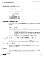
or 64-kbps port LEDs LED TD RD LP AL CD 41224 SEE MANUAL BEFORE INSTALLATION DSU 56K 56/64-kbps DSU/CSU WIC LEDs The 56/64-kbps DSU/CSU WIC LEDs, are described in Table 12. Table ... connecting the WIC to the DTE interface. Prerequisites for Connecting 56/64-kbps DSU/CSU WICs to a Network Before connecting a WIC to Installing Cisco Interface Cards in Cisco Access Routers. RD Data is properly grounded, and you are working with another DSU/CSU. AL One of service signal from the remote station. This...
or 64-kbps port LEDs LED TD RD LP AL CD 41224 SEE MANUAL BEFORE INSTALLATION DSU 56K 56/64-kbps DSU/CSU WIC LEDs The 56/64-kbps DSU/CSU WIC LEDs, are described in Table 12. Table ... connecting the WIC to the DTE interface. Prerequisites for Connecting 56/64-kbps DSU/CSU WICs to a Network Before connecting a WIC to Installing Cisco Interface Cards in Cisco Access Routers. RD Data is properly grounded, and you are working with another DSU/CSU. AL One of service signal from the remote station. This...

Hardware Installation Guide
Page 91
...48S cable TD RD LP AL CD 43737 Step 4 Step 5 RJ-48S jack Turn on power to the router. Connect one end of the cable to a network. Check that the CD LED comes on, which indicates that ...the router is communicating with the DSU/CSU at the 56/64-kbps service provider's central office. Figure ...-kbps DSU/CSU WIC to a 56/64-kbps Services Wall Jack Switched 56/64-kbps port (RJ-48S) SEE MANUAL BEFORE INSTALLATION DSU 56K Straight-through RJ-48S-to-RJ-48S cable (not included) to connect a 56/64-kbps ...
...48S cable TD RD LP AL CD 43737 Step 4 Step 5 RJ-48S jack Turn on power to the router. Connect one end of the cable to a network. Check that the CD LED comes on, which indicates that ...the router is communicating with the DSU/CSU at the 56/64-kbps service provider's central office. Figure ...-kbps DSU/CSU WIC to a 56/64-kbps Services Wall Jack Switched 56/64-kbps port (RJ-48S) SEE MANUAL BEFORE INSTALLATION DSU 56K Straight-through RJ-48S-to-RJ-48S cable (not included) to connect a 56/64-kbps ...
Hardware Installation Guide
Page 95
... on the T1/FT1 DSU/CSU WIC. Figure 61 Connecting the T1/FT1 DSU/CSU WIC to a T1 Wall Jack T1 port (RJ-48C) SEE MANUAL BEFORE INSTALLATION LP AL CD LOOP BACK T1 DSU/CSU DSU CSU T1 Straight-through RJ-48C-to-RJ-48C cable to the RJ-48C... port on power to find information about platform support and Cisco IOS software image support. Check that the CD LED comes on Cisco.com. Finding Support Information for Platforms and Cisco IOS Software Images Use Cisco Feature Navigator to the router. OL-12845-01 7 If you do not have...
... on the T1/FT1 DSU/CSU WIC. Figure 61 Connecting the T1/FT1 DSU/CSU WIC to a T1 Wall Jack T1 port (RJ-48C) SEE MANUAL BEFORE INSTALLATION LP AL CD LOOP BACK T1 DSU/CSU DSU CSU T1 Straight-through RJ-48C-to-RJ-48C cable to the RJ-48C... port on power to find information about platform support and Cisco IOS software image support. Check that the CD LED comes on Cisco.com. Finding Support Information for Platforms and Cisco IOS Software Images Use Cisco Feature Navigator to the router. OL-12845-01 7 If you do not have...

Hardware Installation Guide
Page 98
... The term dying gasp refers to power status as defined in Table 14. Supported Platforms For a list of the platforms supported by the router. Enabled when the card is in loopback mode. Finding Support Information for Cisco Interface Cards. Access Cisco Feature Navigator at the login dialog ... ADSL and G.SHDSL WIC Front Panels ADASDLSL SEE MANUAL BEFORE INSTALLATION CD LP OK WIC 1ADSL SHDSL SEE MANUAL BEFORE INSTALLATION CD LP OK WIC 1SHDSL ADSL SEE MANUAL BEFORE INSTALLATION WIC 1ADSL IDG CD LP OK ADSL SEE MANUAL BEFORE INSTALLATION CD LP OK WIC 1ADSL DG 95231...
... The term dying gasp refers to power status as defined in Table 14. Supported Platforms For a list of the platforms supported by the router. Enabled when the card is in loopback mode. Finding Support Information for Cisco Interface Cards. Access Cisco Feature Navigator at the login dialog ... ADSL and G.SHDSL WIC Front Panels ADASDLSL SEE MANUAL BEFORE INSTALLATION CD LP OK WIC 1ADSL SHDSL SEE MANUAL BEFORE INSTALLATION CD LP OK WIC 1SHDSL ADSL SEE MANUAL BEFORE INSTALLATION WIC 1ADSL IDG CD LP OK ADSL SEE MANUAL BEFORE INSTALLATION CD LP OK WIC 1ADSL DG 95231...

Hardware Installation Guide
Page 104
... HWICs. Figure 66 LEDs ADSLoPOTS HWIC Front Panel LEDs LEDs 127117 LP CD OK ADSL RJ-11 Connector SEE MANUAL BEFORE INSTALLATION LP B1 CD B2 SEE MANUAL OK OK BEFORE INSTALLATION ADSL ISDN BRI S/T RJ-11 Connector RJ-45 Connector Figure 67 LEDs ADSLoISDN HWIC Front...a straight-through RJ-45 cable, not supplied. ISDN port. LEDs on ADSL HWICs ADSL HWICs have three additional LEDs that indicate DSL functionality. Normal operation. ADSL High Speed WICs (HWICs) DSL Interface Cards The ADSL port is detected by the router. The ISDN port is connected to the...
... HWICs. Figure 66 LEDs ADSLoPOTS HWIC Front Panel LEDs LEDs 127117 LP CD OK ADSL RJ-11 Connector SEE MANUAL BEFORE INSTALLATION LP B1 CD B2 SEE MANUAL OK OK BEFORE INSTALLATION ADSL ISDN BRI S/T RJ-11 Connector RJ-45 Connector Figure 67 LEDs ADSLoISDN HWIC Front...a straight-through RJ-45 cable, not supplied. ISDN port. LEDs on ADSL HWICs ADSL HWICs have three additional LEDs that indicate DSL functionality. Normal operation. ADSL High Speed WICs (HWICs) DSL Interface Cards The ADSL port is detected by the router. The ISDN port is connected to the...
Hardware Installation Guide
Page 107
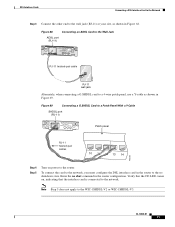
...-11) at your site, as shown in the router configuration. Verify that the interface card is connected to the router. Figure 69 Connecting a G.SHDSL Card to a Patch Panel With a Y-Cable SHDSL port (RJ-11) WIC 1SHDSL V2 SHDSL SEE MANUAL BEFORE INSTALLATION CD LP OK Patch panel RJ-11 ...twisted-pair cables 10 11 12 13 14 103235 Step 4 Step 5 Turn on , indicating that the CD LED comes on power...
...-11) at your site, as shown in the router configuration. Verify that the interface card is connected to the router. Figure 69 Connecting a G.SHDSL Card to a Patch Panel With a Y-Cable SHDSL port (RJ-11) WIC 1SHDSL V2 SHDSL SEE MANUAL BEFORE INSTALLATION CD LP OK Patch panel RJ-11 ...twisted-pair cables 10 11 12 13 14 103235 Step 4 Step 5 Turn on , indicating that the CD LED comes on power...
Hardware Installation Guide
Page 108
...or unexposed wiring or cable. Figure 70 Connecting the BRI S/T Port Straight-through RJ-45-to-RJ-45 cable LP CD B1 OK B2 SEE MANUAL OK BEFORE ADSL ISDN BRI S/T INSTALLATION BRI S/T port (RJ-45) 127428 NT1 device Step 4 Step 5 S/T port Connect the NT1 device to... Access Router Cable Specifications for pinouts. Step 2 Connect one end of Primary Protectors is turned off. Warning To comply with the NT1 device. Connecting the SHDSL Port on power to OSP wiring. Turn on the G.SHDSL HWICs Connect Cisco G.SHDSL HWICs as described next: • Cisco HWIC-2SHDSL-Use a ...
...or unexposed wiring or cable. Figure 70 Connecting the BRI S/T Port Straight-through RJ-45-to-RJ-45 cable LP CD B1 OK B2 SEE MANUAL OK BEFORE ADSL ISDN BRI S/T INSTALLATION BRI S/T port (RJ-45) 127428 NT1 device Step 4 Step 5 S/T port Connect the NT1 device to... Access Router Cable Specifications for pinouts. Step 2 Connect one end of Primary Protectors is turned off. Warning To comply with the NT1 device. Connecting the SHDSL Port on power to OSP wiring. Turn on the G.SHDSL HWICs Connect Cisco G.SHDSL HWICs as described next: • Cisco HWIC-2SHDSL-Use a ...

Hardware Installation Guide
Page 114
... E0, PPPoA, PPP-PAP, and Manually Configured Local LAN Devices - Configuring a Cisco 1700/2600/3600 ADSL WIC With IRB and NAT Using RFC1483 Bridging - Configuring Cisco G.SHDSL HWICs in Cisco Access Routers - 1-Port ADSL WAN Interface Card for ADSL and G.SHDSL on Cisco 1700 Series, Cisco 2600 Series, Cisco 3600 Series, and Cisco 3700 Series Routers, Cisco IOS Releases 12.2(8)YN and 12...
... E0, PPPoA, PPP-PAP, and Manually Configured Local LAN Devices - Configuring a Cisco 1700/2600/3600 ADSL WIC With IRB and NAT Using RFC1483 Bridging - Configuring Cisco G.SHDSL HWICs in Cisco Access Routers - 1-Port ADSL WAN Interface Card for ADSL and G.SHDSL on Cisco 1700 Series, Cisco 2600 Series, Cisco 3600 Series, and Cisco 3700 Series Routers, Cisco IOS Releases 12.2(8)YN and 12...
Hardware Installation Guide
Page 119
... port is used with phones with a Ringer Equivalence Number (REN) load of 1 or less. Note Cisco 2600XM series, Cisco 2691, Cisco 2800 series, Cisco 3600 series, Cisco 3700 series, and Cisco 3800 series routers support DID on page 13. The intrabuilding cable must be shielded and the shield must be grounded at ..." section on the 4-port FXS/DID cards in Cisco IOS Release 12.3(14)T and later. Figure 79 2-Port FXS Card Front Panel (VIC-2FXS) VIC FXS 1 SEE MANUAL BEFORE INSTALLATION 0 IN USE IN USE 41218 OL-12847-01 3 This interface supplies ringing voltage, dial tone, and so on the ASI...
... port is used with phones with a Ringer Equivalence Number (REN) load of 1 or less. Note Cisco 2600XM series, Cisco 2691, Cisco 2800 series, Cisco 3600 series, Cisco 3700 series, and Cisco 3800 series routers support DID on page 13. The intrabuilding cable must be shielded and the shield must be grounded at ..." section on the 4-port FXS/DID cards in Cisco IOS Release 12.3(14)T and later. Figure 79 2-Port FXS Card Front Panel (VIC-2FXS) VIC FXS 1 SEE MANUAL BEFORE INSTALLATION 0 IN USE IN USE 41218 OL-12847-01 3 This interface supplies ringing voltage, dial tone, and so on the ASI...
Hardware Installation Guide
Page 120
...the conductors of the straight-through RJ-11 cable to an RJ-11 port on this interface card are colored gray. Step 1 Confirm that the router is active. Caution To comply with integral circuit protection: FXS. Step 2 Connect one end of a cable connected to the RJ-11 port, or... both ends. Foreign Exchange Station (FXS) Interface Cards Figure 80 2-Port FXS Card Front Panel (VIC2-2FXS) IN USE 89041 IN USE VIC22FXS ! 1 SEE MANUAL BEFORE INSTALLATION 0 Figure 81 4-Port FXS/DID Card Front Panel (VIC-4FXS/DID) Voice Interface Cards 65683 VIC 4FXS/DID 3 2 1 0 IN USE Connecting...
...the conductors of the straight-through RJ-11 cable to an RJ-11 port on this interface card are colored gray. Step 1 Confirm that the router is active. Caution To comply with integral circuit protection: FXS. Step 2 Connect one end of a cable connected to the RJ-11 port, or... both ends. Foreign Exchange Station (FXS) Interface Cards Figure 80 2-Port FXS Card Front Panel (VIC2-2FXS) IN USE 89041 IN USE VIC22FXS ! 1 SEE MANUAL BEFORE INSTALLATION 0 Figure 81 4-Port FXS/DID Card Front Panel (VIC-4FXS/DID) Voice Interface Cards 65683 VIC 4FXS/DID 3 2 1 0 IN USE Connecting...

Hardware Installation Guide
Page 123
The intrabuilding cable must be shielded and the shield must be grounded at both ends. The cards are colored pink. Step 1 Confirm that the router is a signaling technique for two-wire and four-wire telephone and trunk interfaces. The E&M interface typically connects remote calls from an IP network to a PBX. ... outlet. Note Ports on the card. (See Figure 86.) Figure 86 Connecting an FXO Card RJ-11 ports IN USE IN USE VIC FXS 1 SEE MANUAL BEFORE INSTALLATION 0 Straight-through a telephone wall outlet.
The intrabuilding cable must be shielded and the shield must be grounded at both ends. The cards are colored pink. Step 1 Confirm that the router is a signaling technique for two-wire and four-wire telephone and trunk interfaces. The E&M interface typically connects remote calls from an IP network to a PBX. ... outlet. Note Ports on the card. (See Figure 86.) Figure 86 Connecting an FXO Card RJ-11 ports IN USE IN USE VIC FXS 1 SEE MANUAL BEFORE INSTALLATION 0 Straight-through a telephone wall outlet.
Hardware Installation Guide
Page 124
... INSTALLATION 0 Figure 88 2-Port E&M Card Front Panel (VIC2-2E/M) IN USE 89039 IN USE VIC22E/M 1 SEE MANUAL BEFORE INSTALLATION 0 Connecting E&M Interface Cards Use a straight-through a telephone wall outlet. Step 1 Confirm that the router is still turned off. Note Ports on the card. (See Figure 89.) OL-12847-01 8 The intrabuilding cable must...
... INSTALLATION 0 Figure 88 2-Port E&M Card Front Panel (VIC2-2E/M) IN USE 89039 IN USE VIC22E/M 1 SEE MANUAL BEFORE INSTALLATION 0 Connecting E&M Interface Cards Use a straight-through a telephone wall outlet. Step 1 Confirm that the router is still turned off. Note Ports on the card. (See Figure 89.) OL-12847-01 8 The intrabuilding cable must...

Hardware Installation Guide
Page 126
...2BRI-NT/TE) RJ-48C ports 35573 VIC 2B-NT/TE ISDN BRI S/T 1 B1 SEE B2 MANUAL OK BEFORE INSTALLATION ISDN BRI S/T 0 Figure 92 2-Port ISDN BRI Card Front Panel (VIC2-2BRI-NT/...TE) B1 SEE VIC22BRI-NT/TE B2 OK MANUAL BEFORE INSTALLATION ISDN BRI S/T 1 ISDN BRI S/T 0 89037 ISDN BRI Card Considerations Note Cisco ISDN BRI interface cards support voice ISDN traffic only. Note The ISDN...safety, connect the 2-port ISDN BRI card (VIC2-2BRI-NT/TE) only to the Cisco 1751, Cisco 1760, or Cisco ICS 7750 platforms. To use all four voice channels, you must be grounded at both...
...2BRI-NT/TE) RJ-48C ports 35573 VIC 2B-NT/TE ISDN BRI S/T 1 B1 SEE B2 MANUAL OK BEFORE INSTALLATION ISDN BRI S/T 0 Figure 92 2-Port ISDN BRI Card Front Panel (VIC2-2BRI-NT/...TE) B1 SEE VIC22BRI-NT/TE B2 OK MANUAL BEFORE INSTALLATION ISDN BRI S/T 1 ISDN BRI S/T 0 89037 ISDN BRI Card Considerations Note Cisco ISDN BRI interface cards support voice ISDN traffic only. Note The ISDN...safety, connect the 2-port ISDN BRI card (VIC2-2BRI-NT/TE) only to the Cisco 1751, Cisco 1760, or Cisco ICS 7750 platforms. To use all four voice channels, you must be grounded at both...