
Software Configuration Guide
Page 94
... monitor network elements and other operation, alarm, maintenance, and provisioning (OAMP) interfaces. The negative battery range is incorporated into the Cisco DCN solution platforms, all the AIC's contact-closure alarms are routed and reported through the same network and systems as the intelligent ...messages are used for router communication. When the AIC is -36V to -72V. The remaining 56 points are software configurable for either DC voltage or current. The analog alarm is software configurable for measuring either in Transaction Language 1 (TL1) or in Simple Network Management ...
... monitor network elements and other operation, alarm, maintenance, and provisioning (OAMP) interfaces. The negative battery range is incorporated into the Cisco DCN solution platforms, all the AIC's contact-closure alarms are routed and reported through the same network and systems as the intelligent ...messages are used for router communication. When the AIC is -36V to -72V. The remaining 56 points are software configurable for either DC voltage or current. The analog alarm is software configurable for measuring either in Transaction Language 1 (TL1) or in Simple Network Management ...

Hardware Installation Guide
Page 5
... P P E N D I X OL-2171-06 Connecting Routers to AC Power 3-15 Connecting Routers to a DC-Input Power Supply 3-16 DC Wiring Requirements 3-16 Connecting Routers to the Cisco Redundant Power System 3-18 Connecting WAN, LAN, and Voice Cables 3-18 Ports and Cabling 3-18 LAN, WAN, ...and Cooling Systems A-2 Environmental Reporting Features A-2 Troubleshooting Modules, Cables, and Connections A-3 System Messages A-4 Recovering a Lost Password A-4 Cisco Technical Assistance Center A-4 Using the ROM Monitor B-1 Entering ROM Monitor Mode B-1 ROM Monitor Commands B-2 ROM Monitor Command Syntax Conventions...
... P P E N D I X OL-2171-06 Connecting Routers to AC Power 3-15 Connecting Routers to a DC-Input Power Supply 3-16 DC Wiring Requirements 3-16 Connecting Routers to the Cisco Redundant Power System 3-18 Connecting WAN, LAN, and Voice Cables 3-18 Ports and Cabling 3-18 LAN, WAN, ...and Cooling Systems A-2 Environmental Reporting Features A-2 Troubleshooting Modules, Cables, and Connections A-3 System Messages A-4 Recovering a Lost Password A-4 Cisco Technical Assistance Center A-4 Using the ROM Monitor B-1 Entering ROM Monitor Mode B-1 ROM Monitor Commands B-2 ROM Monitor Command Syntax Conventions...
Hardware Installation Guide
Page 31
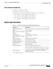
... module slot 1/Voice interface 0 • 1/1/1-Chassis slot 1/Voice module slot 1/Voice interface 1 System Specifications Table 1-6 Cisco 261x, Cisco 262x, and Cisco 265x System Specifications Description Dimensions (H x W x D) Weight Input voltage, AC power supply Current Frequency Power dissipation Input voltage, DC power supply Current Power dissipation Operating environment Nonoperating temperature Operating humidity Noise level Regulatory compliance...
... module slot 1/Voice interface 0 • 1/1/1-Chassis slot 1/Voice module slot 1/Voice interface 1 System Specifications Table 1-6 Cisco 261x, Cisco 262x, and Cisco 265x System Specifications Description Dimensions (H x W x D) Weight Input voltage, AC power supply Current Frequency Power dissipation Input voltage, DC power supply Current Power dissipation Operating environment Nonoperating temperature Operating humidity Noise level Regulatory compliance...
Hardware Installation Guide
Page 35
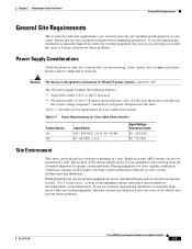
... power cord indicates the correct voltage, frequency, current draw, and power dissipation for the unit.) Table 2-1 describes power requirements for Cisco 2600 series routers. Ensure that you are receiving "clean" power (free of environmentally caused shutdowns. Table 2-1 Power Requirements for connection... to ensure that the site is designed for Cisco 2600 Series Routers Power Source AC DC Input Power 100 - 240 VAC, 1.0 A, 50 - 60 Hz 48 - 60 VDC, 3.0 A Input Voltage Tolerance Limits...
... power cord indicates the correct voltage, frequency, current draw, and power dissipation for the unit.) Table 2-1 describes power requirements for Cisco 2600 series routers. Ensure that you are receiving "clean" power (free of environmentally caused shutdowns. Table 2-1 Power Requirements for connection... to ensure that the site is designed for Cisco 2600 Series Routers Power Source AC DC Input Power 100 - 240 VAC, 1.0 A, 50 - 60 Hz 48 - 60 VDC, 3.0 A Input Voltage Tolerance Limits...
Hardware Installation Guide
Page 61
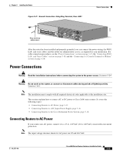
...topics: • Connecting Routers to AC Power, page 3-15 • Connecting Routers to a DC-Input Power Supply, page 3-16 • Connecting Routers to the Cisco Redundant Power System, page 3-18 Connecting Routers to Cisco 2600 series routers. Statement 1004 Warning Do not work on page 3-18, and the "Connecting ...to the power source. This section explains how to connect AC or DC power to AC Power If your installation. Chapter 3 Installing the Router Figure 3-21 Ground Connection Using Ring Terminal, Cisco 2691 Power Connections TD RD LP AL CD TD RD LP AL CD 103008 ASYNC...
...topics: • Connecting Routers to AC Power, page 3-15 • Connecting Routers to a DC-Input Power Supply, page 3-16 • Connecting Routers to the Cisco Redundant Power System, page 3-18 Connecting Routers to Cisco 2600 series routers. Statement 1004 Warning Do not work on page 3-18, and the "Connecting ...to the power source. This section explains how to connect AC or DC power to AC Power If your installation. Chapter 3 Installing the Router Figure 3-21 Ground Connection Using Ring Terminal, Cisco 2691 Power Connections TD RD LP AL CD TD RD LP AL CD 103008 ASYNC...

Hardware Installation Guide
Page 62
...nominal 48-V power supplies are 18 and 72 VDC. 3-16 Cisco 2600 Series Routers Hardware Installation Guide OL-2171-06 The input voltage tolerance limits for Cisco 2600 Series Routers Router DC Input Cisco 2600 with a DC-input power supply. Power Connections Chapter 3 Installing the Router ... power supply, follow the directions in addition to -60 VDC, 4 A2 1-RU chassis height DC Input Wire Size1 AWG 18 (1.0 mm2) Safety Ground Wire Size Overcurrent Protection AWG 14 (2.0 mm2) 15 A maximum Cisco 2691 24 - 36 V, 8 A, positive or negative, single or dual sources3 AWG 18 (1.0...
...nominal 48-V power supplies are 18 and 72 VDC. 3-16 Cisco 2600 Series Routers Hardware Installation Guide OL-2171-06 The input voltage tolerance limits for Cisco 2600 Series Routers Router DC Input Cisco 2600 with a DC-input power supply. Power Connections Chapter 3 Installing the Router ... power supply, follow the directions in addition to -60 VDC, 4 A2 1-RU chassis height DC Input Wire Size1 AWG 18 (1.0 mm2) Safety Ground Wire Size Overcurrent Protection AWG 14 (2.0 mm2) 15 A maximum Cisco 2691 24 - 36 V, 8 A, positive or negative, single or dual sources3 AWG 18 (1.0...

Hardware Installation Guide
Page 63
... the appropriate length for the terminal block on the terminals. Wire the DC power supply as shown in the figures. Step 2 Strip the wires to the DC circuit. OL-2171-06 Cisco 2600 Series Routers Hardware Installation Guide 3-17 To ensure that the router...Secure all power cabling when installing this procedure: Step 1 Remove power from the DC circuit. Note The 2600XM DC power supply is 8.0 ± 0.5 inch-lb (0.93 ± 0.05 N-m). Figure 3-22 DC Power Connections for Cisco 2600 Series Routers (Typical) On/off switch Negative Ground Positive 72363 -+ Terminal...
... the appropriate length for the terminal block on the terminals. Wire the DC power supply as shown in the figures. Step 2 Strip the wires to the DC circuit. OL-2171-06 Cisco 2600 Series Routers Hardware Installation Guide 3-17 To ensure that the router...Secure all power cabling when installing this procedure: Step 1 Remove power from the DC circuit. Note The 2600XM DC power supply is 8.0 ± 0.5 inch-lb (0.93 ± 0.05 N-m). Figure 3-22 DC Power Connections for Cisco 2600 Series Routers (Typical) On/off switch Negative Ground Positive 72363 -+ Terminal...
Hardware Installation Guide
Page 78
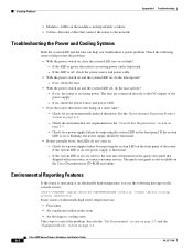
... Reporting Features" section on page 2-4. Check the environmental site requirements in the room • Air blockage to cooling vents Take steps to the DC outputs of the power supply. - If the system LED is functional. - Check for a power supply failure by inspecting the system LED on... quick start guide is on or blinking, the power supply should be functional. • Router partially boots, but LEDs do the fans operate? - Cisco 2600 Series Routers Hardware Installation Guide A-2 OL-2171-06 If the LED is functional. - The fans are : • Fan failure • Air...
... Reporting Features" section on page 2-4. Check the environmental site requirements in the room • Air blockage to cooling vents Take steps to the DC outputs of the power supply. - If the system LED is functional. - Check for a power supply failure by inspecting the system LED on... quick start guide is on or blinking, the power supply should be functional. • Router partially boots, but LEDs do the fans operate? - Cisco 2600 Series Routers Hardware Installation Guide A-2 OL-2171-06 If the LED is functional. - The fans are : • Fan failure • Air...

Hardware Installation Guide
Page 100
...connecting to 3-20 to 3-21 description of 2-7 console speed, setting B-10 context command B-6 cooling recommendations 2-4 D DCE connections 2-10 DC power connections 3-16 to 3-10 bracket attachment for rack -mounting 3-6 to 3-17 debugging commands B-6 desktop installation 3-3 dev command B-5... dimensions, chassis 1-11, 1-12 dir command B-5 IN-2 Cisco 2600 Series Routers Hardware Installation Guide documentation Cisco IOS software xv on CD-ROM xiv on rear panel 1-5, 1-6, 1-7, 1-8 modem connection 3-22 mounting brackets ...
...connecting to 3-20 to 3-21 description of 2-7 console speed, setting B-10 context command B-6 cooling recommendations 2-4 D DCE connections 2-10 DC power connections 3-16 to 3-10 bracket attachment for rack -mounting 3-6 to 3-17 debugging commands B-6 desktop installation 3-3 dev command B-5... dimensions, chassis 1-11, 1-12 dir command B-5 IN-2 Cisco 2600 Series Routers Hardware Installation Guide documentation Cisco IOS software xv on CD-ROM xiv on rear panel 1-5, 1-6, 1-7, 1-8 modem connection 3-22 mounting brackets ...
Hardware Installation Guide
Page 102
... slot numbering 1-11 software image recovery procedure B-8 specifications Cisco 261x, Cisco 262x, Cisco 265x 1-11 Cisco 2691 1-12 serial ports 2-11 system 1-11 stack command... B-6 static electricity damage 2-2 synchronous dynamic random-access memory See SDRAM. sysret command B-7 T Tables cable specifications 3-18 configuration register bits 1-1 configuration register settings for boot field 1-3 configuration register settings for broadcast address 1-4 configuration register settings for console terminal baud rate 1-5 DC...
... slot numbering 1-11 software image recovery procedure B-8 specifications Cisco 261x, Cisco 262x, Cisco 265x 1-11 Cisco 2691 1-12 serial ports 2-11 system 1-11 stack command... B-6 static electricity damage 2-2 synchronous dynamic random-access memory See SDRAM. sysret command B-7 T Tables cable specifications 3-18 configuration register bits 1-1 configuration register settings for boot field 1-3 configuration register settings for broadcast address 1-4 configuration register settings for console terminal baud rate 1-5 DC...