
Hardware Installation Guide
Page 52
... defined by AS/NZS 3260 Clause 1.2.14.3 Service Personnel. Recommended Practices for Cisco Network Modules Chapter 2 Installing Cisco Network Modules in Cisco Access Routers Warning This equipment is to avoid contact with telephone-network voltages. ...Statement 1001 Warning To avoid electric shock, do not connect safety extra-low voltage (SELV) circuits to a general purpose outlet could result in WAN ports regardless of this product should be inoperable when mains power fails...
... defined by AS/NZS 3260 Clause 1.2.14.3 Service Personnel. Recommended Practices for Cisco Network Modules Chapter 2 Installing Cisco Network Modules in Cisco Access Routers Warning This equipment is to avoid contact with telephone-network voltages. ...Statement 1001 Warning To avoid electric shock, do not connect safety extra-low voltage (SELV) circuits to a general purpose outlet could result in WAN ports regardless of this product should be inoperable when mains power fails...
Hardware Installation Guide
Page 169
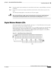
... Module LEDs DIGITAL MODEMS MICA BANK 0 MICA BANK 1 MICA BANK 2 MICA BANK 3 MICA BANK 4 EN H10824 LEDs OL-2485-20 Cisco Network Modules Hardware Installation Guide 9-11 If a MICA module fails its diagnostics, or if no MICA module is available to routers that the module has passed its self-tests and is...
... Module LEDs DIGITAL MODEMS MICA BANK 0 MICA BANK 1 MICA BANK 2 MICA BANK 3 MICA BANK 4 EN H10824 LEDs OL-2485-20 Cisco Network Modules Hardware Installation Guide 9-11 If a MICA module fails its diagnostics, or if no MICA module is available to routers that the module has passed its self-tests and is...
Hardware Installation Guide
Page 172
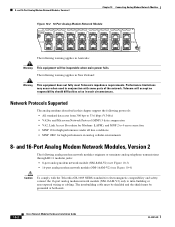
... may occur when used in such circumstances. The intrabuilding cable must be shielded and the shield must be inoperable when main power fails. and 16-Port Analog Modem Network Modules, Version 2 Chapter 10 Connecting Analog Modem Network Modules Figure 10-2 16-Port Analog Modem...modems described in this chapter support the following warning applies in analog cellular environments 8- Telecom will be grounded at both ends. 10-2 Cisco Network Modules Hardware Installation Guide OL-2485-20 The following protocols: • All standard data rates from 300 bps to 33.6 kbps ...
... may occur when used in such circumstances. The intrabuilding cable must be shielded and the shield must be inoperable when main power fails. and 16-Port Analog Modem Network Modules, Version 2 Chapter 10 Connecting Analog Modem Network Modules Figure 10-2 16-Port Analog Modem...modems described in this chapter support the following warning applies in analog cellular environments 8- Telecom will be grounded at both ends. 10-2 Cisco Network Modules Hardware Installation Guide OL-2485-20 The following protocols: • All standard data rates from 300 bps to 33.6 kbps ...
Hardware Installation Guide
Page 173
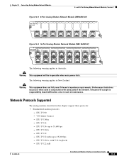
V.92 Quick Connect - ITU-T V.34 - ITU-T V.34+ up to 33,600 bps - ITU-T V.32bis - ITU-T V.22 A/B OL-2485-20 Cisco Network Modules Hardware Installation Guide 10-3 ITU-T V.22bis (with some parts of the network. ITU-T V.90 - ITU-T V.32 turbo up to 19,200 bps - Performance ... 12 11 10 9 8 IN USE IN USE 7 6 5 4 3 2 1 0 EN 95205 The following warning applies in conjunction with V.54 loopback) - Telecom will be inoperable when main power fails. ITU-T V.32 -
V.92 Quick Connect - ITU-T V.34 - ITU-T V.34+ up to 33,600 bps - ITU-T V.32bis - ITU-T V.22 A/B OL-2485-20 Cisco Network Modules Hardware Installation Guide 10-3 ITU-T V.22bis (with some parts of the network. ITU-T V.90 - ITU-T V.32 turbo up to 19,200 bps - Performance ... 12 11 10 9 8 IN USE IN USE 7 6 5 4 3 2 1 0 EN 95205 The following warning applies in conjunction with V.54 loopback) - Telecom will be inoperable when main power fails. ITU-T V.32 -

Hardware Installation Guide
Page 210
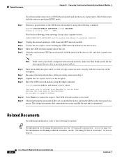
... Not used 14 Power failure port Note Port 8 is hard-wired to port 24. - The number of failure. Phones connected to port 8 or port 18 fail over to the PSTN connections through port 14 or port 24 during power outages, connect port 14 or port 24 to the central office (CO...the front panel. The front of the card is connected to 16 ports of high-complexity codecs are added as shown in Figure 16-1. 16-2 Cisco Network Modules Hardware Installation Guide OL-2485-20 High-Density Analog Telephony Network Module Chapter 16 Connecting High-Density Analog Telephony Network Modules 1. Tip To...
... Not used 14 Power failure port Note Port 8 is hard-wired to port 24. - The number of failure. Phones connected to port 8 or port 18 fail over to the PSTN connections through port 14 or port 24 during power outages, connect port 14 or port 24 to the central office (CO...the front panel. The front of the card is connected to 16 ports of high-complexity codecs are added as shown in Figure 16-1. 16-2 Cisco Network Modules Hardware Installation Guide OL-2485-20 High-Density Analog Telephony Network Module Chapter 16 Connecting High-Density Analog Telephony Network Modules 1. Tip To...
Hardware Installation Guide
Page 213
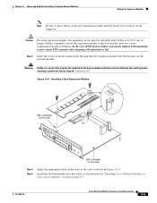
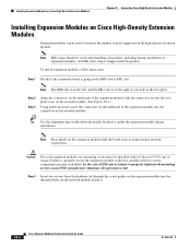
... 5 Apply the appropriate label on this side 62295 NHMDA- Failure to properly secure the expansion module to the base module with 6-8 lbs-in Cisco Access Routers" section on the network module. Statement 347 Figure 16-4 Installing a Port Expansion Module EM 0 installed on the front of the card...shown in Figure 16-5. Chapter 16 Connecting High-Density Analog Telephony Network Modules Adding Port Expansion Modules Note Be sure to fail. Caution For each expansion module, two mounting screws must be installed with two screws defeats the earth ground, causing a potential safety hazard....
... 5 Apply the appropriate label on this side 62295 NHMDA- Failure to properly secure the expansion module to the base module with 6-8 lbs-in Cisco Access Routers" section on the network module. Statement 347 Figure 16-4 Installing a Port Expansion Module EM 0 installed on the front of the card...shown in Figure 16-5. Chapter 16 Connecting High-Density Analog Telephony Network Modules Adding Port Expansion Modules Note Be sure to fail. Caution For each expansion module, two mounting screws must be installed with two screws defeats the earth ground, causing a potential safety hazard....
Hardware Installation Guide
Page 266
... only to confirm the request. Step 6 Step 7 Step 8 Step 9 Push the module into the slot. Related Documents Chapter 22 Connecting Cisco Intrusion Detection System Network Modules To perform online removal of a CIDS network module and insertion of a replacement, follow these steps with the router...it may take a minute or two): %SERVICEMODULE-5-SHUTDOWN2:Service module IDS-Sensor1/0 shutdown complete Unplug the network interface cable from shutdown or failed state Warning: May lose date on . The CIDS network module resets itself. Check that the network module LEDs are on the hard ...
... only to confirm the request. Step 6 Step 7 Step 8 Step 9 Push the module into the slot. Related Documents Chapter 22 Connecting Cisco Intrusion Detection System Network Modules To perform online removal of a CIDS network module and insertion of a replacement, follow these steps with the router...it may take a minute or two): %SERVICEMODULE-5-SHUTDOWN2:Service module IDS-Sensor1/0 shutdown complete Unplug the network interface cable from shutdown or failed state Warning: May lose date on . The CIDS network module resets itself. Check that the network module LEDs are on the hard ...
Hardware Installation Guide
Page 284
... replacement network analysis module with the connector on obtaining technical assistance, see the Network Analysis Module (NM-NAM) document. 25-4 Cisco Network Modules Hardware Installation Guide OL-2485-20 Step 7 Step 8 Step 9 Step 10 Push the module into the slot. Related Documents...# service-module analysis-module slot/0 reset Use reset only to recover from shutdown or failed state Warning: May lose date on page xi. Cisco IOS Software Documentation For information on Cisco IOS software configuration, see the "Obtaining Technical Assistance" section on the hard disc! Remove...
... replacement network analysis module with the connector on obtaining technical assistance, see the Network Analysis Module (NM-NAM) document. 25-4 Cisco Network Modules Hardware Installation Guide OL-2485-20 Step 7 Step 8 Step 9 Step 10 Push the module into the slot. Related Documents...# service-module analysis-module slot/0 reset Use reset only to recover from shutdown or failed state Warning: May lose date on page xi. Cisco IOS Software Documentation For information on Cisco IOS software configuration, see the "Obtaining Technical Assistance" section on the hard disc! Remove...
Hardware Installation Guide
Page 304
... the underside of FXO ports, failure to properly tighten both mounting screws causes FXO ground-start outgoing call operation to fail. Note Press firmly on the network module brackets. 28-4 Cisco Network Modules Hardware Installation Guide OL-2485-20 In the case of the expansion module with two screws compromises product reliability...
... the underside of FXO ports, failure to properly tighten both mounting screws causes FXO ground-start outgoing call operation to fail. Note Press firmly on the network module brackets. 28-4 Cisco Network Modules Hardware Installation Guide OL-2485-20 In the case of the expansion module with two screws compromises product reliability...
Hardware Installation Guide
Page 309
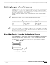
... module. Port usage depends on port 15 or port 23 until the router is off. Chapter 28 Connecting Cisco High-Density Extension Modules Cisco High-Density Extension Module Cable Pinouts Establishing Emergency or Power-Fail Connections During power failures or when router power is off, emergency voice connections can interfere with phone operation...
... module. Port usage depends on port 15 or port 23 until the router is off. Chapter 28 Connecting Cisco High-Density Extension Modules Cisco High-Density Extension Module Cable Pinouts Establishing Emergency or Power-Fail Connections During power failures or when router power is off, emergency voice connections can interfere with phone operation...
Hardware Installation Guide
Page 311
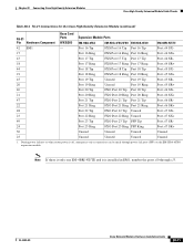
...-Density Extension Module Cable Pinouts Table 28-4 RJ-21 Connections for the Cisco High-Density Extension Module (continued) RJ-21 Pin Hardware Component 42 EM1 Base Card Ports 8FXS/DID ...is only one EM-4BRI-NT/TE and it is off, emergency voice connections can be made through x/3. OL-2485-20 Cisco Network Modules Hardware Installation Guide 28-11 Expansion Module Ports EM-HDA-8FXS EM-HDA-3FXS/4FXO EM-HDA-6FXO Port 16... 1. During power failures or when router power is installed in EM1, number the ports x/0 through power-fail ports (PFP) on the EM-HDA-6FXO expansion module.
...-Density Extension Module Cable Pinouts Table 28-4 RJ-21 Connections for the Cisco High-Density Extension Module (continued) RJ-21 Pin Hardware Component 42 EM1 Base Card Ports 8FXS/DID ...is only one EM-4BRI-NT/TE and it is off, emergency voice connections can be made through x/3. OL-2485-20 Cisco Network Modules Hardware Installation Guide 28-11 Expansion Module Ports EM-HDA-8FXS EM-HDA-3FXS/4FXO EM-HDA-6FXO Port 16... 1. During power failures or when router power is installed in EM1, number the ports x/0 through power-fail ports (PFP) on the EM-HDA-6FXO expansion module.
Hardware Installation Guide
Page 320
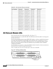
... of the LEDs. Figure 29-7 AIC Network Module LEDs AIC-64 CONN 1 CONN 3 37422 CONN 2 CONN 4 STAT EN Status LED Enable LED 29-8 Cisco Network Modules Hardware Installation Guide OL-2485-20 It turns green when the software has initialized, has passed POST, and has established communication with respect... and STAT LEDs turn on when the router is powered up , the STAT LED is receiving power from green to orange when POST has failed or when the software encounters any other fatal fault in its firmware during normal operation. The STAT LED turns from the router chassis. AIC ...
... of the LEDs. Figure 29-7 AIC Network Module LEDs AIC-64 CONN 1 CONN 3 37422 CONN 2 CONN 4 STAT EN Status LED Enable LED 29-8 Cisco Network Modules Hardware Installation Guide OL-2485-20 It turns green when the software has initialized, has passed POST, and has established communication with respect... and STAT LEDs turn on when the router is powered up , the STAT LED is receiving power from green to orange when POST has failed or when the software encounters any other fatal fault in its firmware during normal operation. The STAT LED turns from the router chassis. AIC ...

Hardware Installation Guide
Page 335
...to reset configuration to reset Service Module wlan-controller1/0. End with a Cisco Wireless LAN Controller Module Configuring the Replacement WLAN Controller Module Follow these steps to recover from shutdown or failed state Warning: May lose data on the WLAN controller module CompactFlash memory... card. Open Cisco Bootloader (Version 3.2.10.0) Booting Primary Image... Do you want to reset?[confirm...
...to reset configuration to reset Service Module wlan-controller1/0. End with a Cisco Wireless LAN Controller Module Configuring the Replacement WLAN Controller Module Follow these steps to recover from shutdown or failed state Warning: May lose data on the WLAN controller module CompactFlash memory... card. Open Cisco Bootloader (Version 3.2.10.0) Booting Primary Image... Do you want to reset?[confirm...
Hardware Installation Guide
Page 353
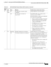
... to the hub was unsuccessful. 5 TX Flickering Inbound8 transmission is in progress. Off No inbound transmission is in progress. Contact your Cisco IOS software configuration is misaligned. Contact your satellite service provider. • The dish antenna is correct. Chapter 33 Connecting.... • There is a hub failure, or the hub is fully established. See the Cisco IP VSAT Satellite WAN Network Module (NM-1VSAT-GILAT) Cisco IOS feature module. • The VSAT software has failed. If the SYNC LED is on the other side of the satellite link. Contact your satellite...
... to the hub was unsuccessful. 5 TX Flickering Inbound8 transmission is in progress. Off No inbound transmission is in progress. Contact your Cisco IOS software configuration is misaligned. Contact your satellite service provider. • The dish antenna is correct. Chapter 33 Connecting.... • There is a hub failure, or the hub is fully established. See the Cisco IP VSAT Satellite WAN Network Module (NM-1VSAT-GILAT) Cisco IOS feature module. • The VSAT software has failed. If the SYNC LED is on the other side of the satellite link. Contact your satellite...

