

Hardware Installation Guide
Page 12
...Installation Guide xii OL-2485-20 To provide feedback about the Cisco.com website or a particular technical document, click Contacts & Feedback at this URL: http://www.cisco.com/techsupport/contacts Definitions of your situation, the TAC Service Request Tool provides recommended solutions.... Severity 1 (S1)-An existing network is "down or severely degraded.) Cisco engineers are those in a standard format, Cisco has established severity definitions. You and Cisco will commit resources during normal business hours to satisfactory levels. If your issue is ...
...Installation Guide xii OL-2485-20 To provide feedback about the Cisco.com website or a particular technical document, click Contacts & Feedback at this URL: http://www.cisco.com/techsupport/contacts Definitions of your situation, the TAC Service Request Tool provides recommended solutions.... Severity 1 (S1)-An existing network is "down or severely degraded.) Cisco engineers are those in a standard format, Cisco has established severity definitions. You and Cisco will commit resources during normal business hours to satisfactory levels. If your issue is ...
Hardware Installation Guide
Page 138
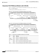
... Port 1 is configured for balanced E1. Interface is connected to the bantam monitor connector. For LEDs found on the network module. 7-14 Cisco Network Modules Hardware Installation Guide OL-2485-20 Port 0 is installed on all PRI network modules, see Table 7-4. An advanced integration module (...AIM) is connected to the bantam monitor connector. See Table 7-5 for balanced T1. Interface is configured for LED definitions. Figure 7-19 1-Port Channelized T1/E1 PRI Network Module with G.703 LEDs NM-1CE1T1-PRI RX MON TX MON C0 C0 CD LP ...
... Port 1 is configured for balanced E1. Interface is connected to the bantam monitor connector. For LEDs found on the network module. 7-14 Cisco Network Modules Hardware Installation Guide OL-2485-20 Port 0 is installed on all PRI network modules, see Table 7-4. An advanced integration module (...AIM) is connected to the bantam monitor connector. See Table 7-5 for balanced T1. Interface is configured for LED definitions. Figure 7-19 1-Port Channelized T1/E1 PRI Network Module with G.703 LEDs NM-1CE1T1-PRI RX MON TX MON C0 C0 CD LP ...
Hardware Installation Guide
Page 308
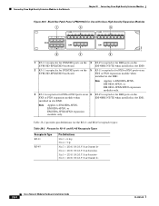
... for FXS/DID ports on the 5 RJ-11 receptacles for FXS or FXO ports on the EVM-HD-8FXS/DID baseboard. Table 28-2 provides pin definitions for the RJ-11 and RJ-45 receptacle types: Table 28-2 Pinouts for RJ-11 and RJ-45 Receptacle Types Receptacle Type RJ-11 RJ...-45 Pin Definitions Pin 3 = Ring Pin 4 = Tip Pin 3 = ISD N BRI-S/T BusTransm it - 28-8 Cisco Network Modules Hardware Installation Guide OL-2485-20 FXS or FXO expansion module when installed in slot EM0. EM-4BRI...
... for FXS/DID ports on the 5 RJ-11 receptacles for FXS or FXO ports on the EVM-HD-8FXS/DID baseboard. Table 28-2 provides pin definitions for the RJ-11 and RJ-45 receptacle types: Table 28-2 Pinouts for RJ-11 and RJ-45 Receptacle Types Receptacle Type RJ-11 RJ...-45 Pin Definitions Pin 3 = Ring Pin 4 = Tip Pin 3 = ISD N BRI-S/T BusTransm it - 28-8 Cisco Network Modules Hardware Installation Guide OL-2485-20 FXS or FXO expansion module when installed in slot EM0. EM-4BRI...