

Hardware Installation Guide
Page 24
... 12-in-1-see Table 1-4 for NM-CEM-4SER part numbers Cisco Smart serial extended 12-in-1-see Table 1-5 for single-mode intermediate (SMI) reach. NM-1ATM-25 NM-1A-T3 NM-1A-T3/E3 NM-1A-E3 NM-1A-T3/E3 NM-1A-OC3-POM NM-...-pin D, blue Cable Micro DB-50 SCSI transition Use with optical loss of 7 dB Note Maximum path length of 45 km (27.9 miles) for single-mode long (SML) reach and 15 km (9.3 miles) for part numbers 1-10 Cisco Network Modules Hardware Installation Guide OL-2485-20
... 12-in-1-see Table 1-4 for NM-CEM-4SER part numbers Cisco Smart serial extended 12-in-1-see Table 1-5 for single-mode intermediate (SMI) reach. NM-1ATM-25 NM-1A-T3 NM-1A-T3/E3 NM-1A-E3 NM-1A-T3/E3 NM-1A-OC3-POM NM-...-pin D, blue Cable Micro DB-50 SCSI transition Use with optical loss of 7 dB Note Maximum path length of 45 km (27.9 miles) for single-mode long (SML) reach and 15 km (9.3 miles) for part numbers 1-10 Cisco Network Modules Hardware Installation Guide OL-2485-20

Hardware Installation Guide
Page 35
... Modules (continued) Product Description 1-port ATM OC-3c/STM1 multimode network module Cisco Product ID NM-1A-OC3MM 1-port ATM OC-3c/STM1 single-mode, NM-1A-OC3SMI intermediate-reach network module 1-port ATM OC-3c/STM1 single-mode, NM-1A-OC3SML long-reach network module 1-port ATM OC-3c/STM1 multimode network...
... Modules (continued) Product Description 1-port ATM OC-3c/STM1 multimode network module Cisco Product ID NM-1A-OC3MM 1-port ATM OC-3c/STM1 single-mode, NM-1A-OC3SMI intermediate-reach network module 1-port ATM OC-3c/STM1 single-mode, NM-1A-OC3SML long-reach network module 1-port ATM OC-3c/STM1 multimode network...

Hardware Installation Guide
Page 70
... procedures prior to remove. (See Example 2-1.) Example 2-1 Shutting Down Interfaces on Cisco Network Modules Router(config)# interface fastethernet 1/0 Router(config-if)# shutdown Tip To see the chapter describing your Cisco access router. Enter interface configuration mode and shut down each interface on Cisco Network Modules Router(config)# interface fastethernet 1/0 Router(config-if)# no shutdown...
... procedures prior to remove. (See Example 2-1.) Example 2-1 Shutting Down Interfaces on Cisco Network Modules Router(config)# interface fastethernet 1/0 Router(config-if)# shutdown Tip To see the chapter describing your Cisco access router. Enter interface configuration mode and shut down each interface on Cisco Network Modules Router(config)# interface fastethernet 1/0 Router(config-if)# no shutdown...

Hardware Installation Guide
Page 71
... with the following command: Router# service-module service-engine slot/port shutdown Remove the network module, using the procedure described in the "Installing Cisco Network Modules in privileged EXEC mode: Step 1 Initiate an application and service network module console session using the following command: Router# service-module service-engine slot/port session...
... with the following command: Router# service-module service-engine slot/port shutdown Remove the network module, using the procedure described in the "Installing Cisco Network Modules in privileged EXEC mode: Step 1 Initiate an application and service network module console session using the following command: Router# service-module service-engine slot/port session...

Hardware Installation Guide
Page 86
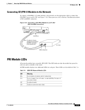
... card slot module (NM-1E1R2W) (see Figure 3-20) • 1-port Fast Ethernet 1-port Token Ring 2-WAN card slot module (NM-1FE2R2W) (see Figure 3-21) 3-10 Cisco Network Modules Hardware Installation Guide OL-2485-20 Figure 3-19 shows 1-port Fast Ethernet network module LEDs as an example. A link has been established with... 10/100 bTX EN COL LINK 100 MBPS FULL DPLX H9982 LEDs Enable LED All network modules have the additional LEDs shown in full-duplex mode. Fast Ethernet network modules have an enable (EN) LED. Interface is 100 Mbps.
... card slot module (NM-1E1R2W) (see Figure 3-20) • 1-port Fast Ethernet 1-port Token Ring 2-WAN card slot module (NM-1FE2R2W) (see Figure 3-21) 3-10 Cisco Network Modules Hardware Installation Guide OL-2485-20 Figure 3-19 shows 1-port Fast Ethernet network module LEDs as an example. A link has been established with... 10/100 bTX EN COL LINK 100 MBPS FULL DPLX H9982 LEDs Enable LED All network modules have the additional LEDs shown in full-duplex mode. Fast Ethernet network modules have an enable (EN) LED. Interface is 100 Mbps.
Hardware Installation Guide
Page 89
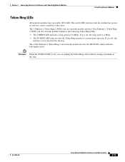
... network module both have an enable (EN) LED. The 1-Fast Ethernet 1-Token Ring 2-slot network module also has the FDX LED, which indicates full-duplex mode. Chapter 3 Connecting Ethernet, Fast Ethernet, and Token Ring Network Modules Token Ring Network Modules Token Ring LEDs All network modules have the following Token Ring... unplug the Token Ring cable without causing a problem on the ring. Timesaver When the IN-RING LED is inserted into the ring. OL-2485-20 Cisco Network Modules Hardware Installation Guide 3-13
... network module both have an enable (EN) LED. The 1-Fast Ethernet 1-Token Ring 2-slot network module also has the FDX LED, which indicates full-duplex mode. Chapter 3 Connecting Ethernet, Fast Ethernet, and Token Ring Network Modules Token Ring Network Modules Token Ring LEDs All network modules have the following Token Ring... unplug the Token Ring cable without causing a problem on the ring. Timesaver When the IN-RING LED is inserted into the ring. OL-2485-20 Cisco Network Modules Hardware Installation Guide 3-13

Hardware Installation Guide
Page 99
... circuit. The following procedures, ensure that services the DC circuit, switch the circuit breaker to the 75-ohm position. OL-2485-20 Cisco Network Modules Hardware Installation Guide 4-9 Remove all power is OFF, locate the circuit breaker on the panel board that power is removed from... applies to unbalanced (75-ohm) position. or 2-Port Channelized E1/ISDN PRI Balanced or Unbalanced Network Modules Configuring Unbalanced Mode To configure the network module for unbalanced mode, follow these steps: Step 1 Turn off electrical power to ground, do not unplug the power cable.
... circuit. The following procedures, ensure that services the DC circuit, switch the circuit breaker to the 75-ohm position. OL-2485-20 Cisco Network Modules Hardware Installation Guide 4-9 Remove all power is OFF, locate the circuit breaker on the panel board that power is removed from... applies to unbalanced (75-ohm) position. or 2-Port Channelized E1/ISDN PRI Balanced or Unbalanced Network Modules Configuring Unbalanced Mode To configure the network module for unbalanced mode, follow these steps: Step 1 Turn off electrical power to ground, do not unplug the power cable.
Hardware Installation Guide
Page 100
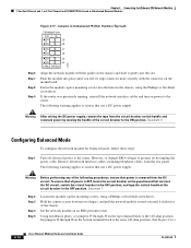
.... Push the module into place until you until it gently into the holes in the OFF position. Statement 8 Configuring Balanced Mode To configure the network module for balanced mode, follow these steps: Step 1 Turn off electrical power to ground, do not unplug the power cable. Statement 7 Step .... To ensure that services the DC circuit, switch the circuit breaker to the same 120-ohm position. (See Figure 4-16.) 4-10 Cisco Network Modules Hardware Installation Guide OL-2485-20 Chapter 4 Connecting Fast Ethernet-PRI Network Modules 1-Port Fast Ethernet and 1- Fasten the module...
.... Push the module into place until you until it gently into the holes in the OFF position. Statement 8 Configuring Balanced Mode To configure the network module for balanced mode, follow these steps: Step 1 Turn off electrical power to ground, do not unplug the power cable. Statement 7 Step .... To ensure that services the DC circuit, switch the circuit breaker to the same 120-ohm position. (See Figure 4-16.) 4-10 Cisco Network Modules Hardware Installation Guide OL-2485-20 Chapter 4 Connecting Fast Ethernet-PRI Network Modules 1-Port Fast Ethernet and 1- Fasten the module...
Hardware Installation Guide
Page 102
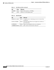
Line or local loopback state is detected. 4-12 Cisco Network Modules Hardware Installation Guide OL-2485-20 Table 4-2 ISDN PRI LEDs LED Color REMOTE ALARM Yellow LOCAL ALARM Yellow LOOPBACK Yellow CARRIER DETECT Green ... Fast Ethernet-PRI Network Modules Table 4-1 Fast Ethernet LEDs (continued) LED 100MBPS FDX Color Green Green Meaning Speed of the interface is in full-duplex mode.
Line or local loopback state is detected. 4-12 Cisco Network Modules Hardware Installation Guide OL-2485-20 Table 4-2 ISDN PRI LEDs LED Color REMOTE ALARM Yellow LOCAL ALARM Yellow LOOPBACK Yellow CARRIER DETECT Green ... Fast Ethernet-PRI Network Modules Table 4-1 Fast Ethernet LEDs (continued) LED 100MBPS FDX Color Green Green Meaning Speed of the interface is in full-duplex mode.
Hardware Installation Guide
Page 103
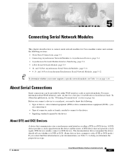
... interface cards or network modules. CH A P T E R 5 Connecting Serial Network Modules This chapter describes how to connect serial network modules for Cisco modular routers and contains the following : • Type of device-data terminal equipment (DTE) or data communications equipment (DCE)-you are connecting to... to the device • Signaling standard required by either a DTE or a DCE device. DTE devices usually connect to select DTE or DCE mode.) If you determine the proper device type. Before you connect a device to a serial port, you need to know the following sections: ...
... interface cards or network modules. CH A P T E R 5 Connecting Serial Network Modules This chapter describes how to connect serial network modules for Cisco modular routers and contains the following : • Type of device-data terminal equipment (DTE) or data communications equipment (DCE)-you are connecting to... to the device • Signaling standard required by either a DTE or a DCE device. DTE devices usually connect to select DTE or DCE mode.) If you determine the proper device type. Before you connect a device to a serial port, you need to know the following sections: ...
Hardware Installation Guide
Page 105
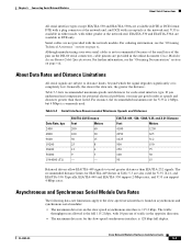
...449 and EIA/TIA-530 support 2-Mbps rates, and V.35 can support 4-Mbps rates. Serial cables are not provided with either mode, with the network module. Chapter 5 Connecting Serial Network Modules About Serial Connections All serial interface types except EIA/TIA-530 and ...V.35 is 2 Mbps, but 4 Mbps is 115.2 kbps. OL-2485-20 Cisco Network Modules Hardware Installation Guide 5-3 The traffic throughput rate allowed is available in the online document Cisco Modular Access Router Cable Specifications. About Data Rates and Distance Limitations All serial signals are...
...449 and EIA/TIA-530 support 2-Mbps rates, and V.35 can support 4-Mbps rates. Serial cables are not provided with either mode, with the network module. Chapter 5 Connecting Serial Network Modules About Serial Connections All serial interface types except EIA/TIA-530 and ...V.35 is 2 Mbps, but 4 Mbps is 115.2 kbps. OL-2485-20 Cisco Network Modules Hardware Installation Guide 5-3 The traffic throughput rate allowed is available in the online document Cisco Modular Access Router Cable Specifications. About Data Rates and Distance Limitations All serial signals are...

Hardware Installation Guide
Page 111
... appropriate serial transition cable, each receptacle determines the port's electrical interface type and mode, DTE or DCE. The serial cable attached to each port on this module can...connect each on port 0 and port 2, or 2 MB on all four ports simultaneously. Cisco 3640 and Cisco 3660 routers only. Note Half-duplex and binary-synchronous communications are not supported on port 0, ... unit/data service unit (CSU/DSU), or other DCE equipment. (See Figure 5-6.) OL-2485-20 Cisco Network Modules Hardware Installation Guide 5-9 After you install a 4-port serial module, use the appropriate serial ...
... appropriate serial transition cable, each receptacle determines the port's electrical interface type and mode, DTE or DCE. The serial cable attached to each port on this module can...connect each on port 0 and port 2, or 2 MB on all four ports simultaneously. Cisco 3640 and Cisco 3660 routers only. Note Half-duplex and binary-synchronous communications are not supported on port 0, ... unit/data service unit (CSU/DSU), or other DCE equipment. (See Figure 5-6.) OL-2485-20 Cisco Network Modules Hardware Installation Guide 5-9 After you install a 4-port serial module, use the appropriate serial ...
Hardware Installation Guide
Page 112
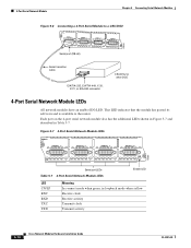
.... Each port on the 4-port serial network module also has the additional LEDs shown in Figure 5-7 and described in loopback mode when yellow Receive clock Receive activity Transmit clock Transmit activity 5-10 Cisco Network Modules Hardware Installation Guide OL-2485-20 4-Port Serial Network Module Chapter 5 Connecting Serial Network Modules Figure 5-6 Connecting... RXC RXD TXC TXD Serial port LEDs Table 5-7 4-Port Serial Network Module LEDs Enable LED LED CN/LP RXC RXD TXC TXD Meaning In connect mode when green, in Table 5-7.
.... Each port on the 4-port serial network module also has the additional LEDs shown in Figure 5-7 and described in loopback mode when yellow Receive clock Receive activity Transmit clock Transmit activity 5-10 Cisco Network Modules Hardware Installation Guide OL-2485-20 4-Port Serial Network Module Chapter 5 Connecting Serial Network Modules Figure 5-6 Connecting... RXC RXD TXC TXD Serial port LEDs Table 5-7 4-Port Serial Network Module LEDs Enable LED LED CN/LP RXC RXD TXC TXD Meaning In connect mode when green, in Table 5-7.
Hardware Installation Guide
Page 116
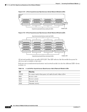
... enable (EN) LED. and 8-Port Asynchronous/Synchronous Serial Network Module LEDs LED CN/LP RXC RXD TXC TXD Meaning In connect mode when green, in Table 5-8. Each port on an asynchronous/synchronous serial network module also has the additional LEDs shown in loopback... mode when yellow Receive clock Receive activity Transmit clock Transmit activity 5-14 Cisco Network Modules Hardware Installation Guide OL-2485-20 This LED indicates that the module has passed its self-...
... enable (EN) LED. and 8-Port Asynchronous/Synchronous Serial Network Module LEDs LED CN/LP RXC RXD TXC TXD Meaning In connect mode when green, in Table 5-8. Each port on an asynchronous/synchronous serial network module also has the additional LEDs shown in loopback... mode when yellow Receive clock Receive activity Transmit clock Transmit activity 5-14 Cisco Network Modules Hardware Installation Guide OL-2485-20 This LED indicates that the module has passed its self-...
Hardware Installation Guide
Page 117
... DTE LED Color Green Green Loopback Yellow Meaning Data terminal ready (DTR) and request to send (STC) are present. The port is in loopback mode OL-2485-20 Cisco Network Modules Hardware Installation Guide 5-15 Data set ready (DSR), data carrier detect (DCD), and clear to send (RTS) are present. When the...
... DTE LED Color Green Green Loopback Yellow Meaning Data terminal ready (DTR) and request to send (STC) are present. The port is in loopback mode OL-2485-20 Cisco Network Modules Hardware Installation Guide 5-15 Data set ready (DSR), data carrier detect (DCD), and clear to send (RTS) are present. When the...
Hardware Installation Guide
Page 137
... at remote end of connection LA Loss of signal, loss of frame, or unavailability because of excessive errors LP Loopback mode CD Carrier received on telco link OL-2485-20 Cisco Network Modules Hardware Installation Guide 7-13 This LED indicates that the module has passed its self-tests and is available to...
... at remote end of connection LA Loss of signal, loss of frame, or unavailability because of excessive errors LP Loopback mode CD Carrier received on telco link OL-2485-20 Cisco Network Modules Hardware Installation Guide 7-13 This LED indicates that the module has passed its self-tests and is available to...

Hardware Installation Guide
Page 146
...Relay Both a 60-channel HDV network module and a voice interface card (VIC) are required to connect to the IP LAN or WAN. In Cisco 3620 and Cisco 3640 routers, at least one or two T1/E1 line interfaces) can be installed in the router to provide the connection to the public... switched telephone network (PSTN) or a PBX. The number of channels supported depends on the number of transport technologies (channelized T1/E1, Frame Relay, Asynchronous Transfer Mode...
...Relay Both a 60-channel HDV network module and a voice interface card (VIC) are required to connect to the IP LAN or WAN. In Cisco 3620 and Cisco 3640 routers, at least one or two T1/E1 line interfaces) can be installed in the router to provide the connection to the public... switched telephone network (PSTN) or a PBX. The number of channels supported depends on the number of transport technologies (channelized T1/E1, Frame Relay, Asynchronous Transfer Mode...

Hardware Installation Guide
Page 152
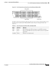
...VoIP over a variety of the NM-HDV2 SKUs. The number of channels supported depends on all of transport technologies (channelized T1, Frame Relay, Asynchronous Transfer Mode [ATM], and others). Table 8-2 Channels Per PVDM2 Module Type Module Name PVDM2-8 PVDM2-16 Max Channels for High Complexity1 4 6 Max Channels for ...packets or frames that can install up to four PVDM2 modules on the number and density-type of Channels for Flexi Complexity3 4-8 6-16 8-10 Cisco Network Modules Hardware Installation Guide OL-2485-20 V0 AL LP CD CTRLR T1/E1 0 PVDM 1 PVDM 0 EN 95197 Figure 8-15 NM...
...VoIP over a variety of the NM-HDV2 SKUs. The number of channels supported depends on all of transport technologies (channelized T1, Frame Relay, Asynchronous Transfer Mode [ATM], and others). Table 8-2 Channels Per PVDM2 Module Type Module Name PVDM2-8 PVDM2-16 Max Channels for High Complexity1 4 6 Max Channels for ...packets or frames that can install up to four PVDM2 modules on the number and density-type of Channels for Flexi Complexity3 4-8 6-16 8-10 Cisco Network Modules Hardware Installation Guide OL-2485-20 V0 AL LP CD CTRLR T1/E1 0 PVDM 1 PVDM 0 EN 95197 Figure 8-15 NM...

Hardware Installation Guide
Page 154
...in T1/E1 port that the jumper is provisioned, you are unsure whether your provider. Figure 8-16 shows the jumper block configured for normal mode, with your E1 line is a small amount of electrical contacts in the module's network connection. These errors can also use the show ... to left. • To configure an E1 port for normal mode, set the jumper to pins 2 and 3. • To configure an E1 port for wetting current mode, set the jumper to look for Normal Mode 135658 J6 J7 Pin 3 Pin 2 Pin 1 8-12 Cisco Network Modules Hardware Installation Guide OL-2485-20
...in T1/E1 port that the jumper is provisioned, you are unsure whether your provider. Figure 8-16 shows the jumper block configured for normal mode, with your E1 line is a small amount of electrical contacts in the module's network connection. These errors can also use the show ... to left. • To configure an E1 port for normal mode, set the jumper to pins 2 and 3. • To configure an E1 port for wetting current mode, set the jumper to look for Normal Mode 135658 J6 J7 Pin 3 Pin 2 Pin 1 8-12 Cisco Network Modules Hardware Installation Guide OL-2485-20
Hardware Installation Guide
Page 177
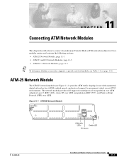
... ATM 0 TX RX EN 11705 ATM traffic LEDs Enable LED RJ-45 port OL-2485-20 Cisco Network Modules Hardware Installation Guide 11-1 11 C H A P T E R Connecting ATM Network Modules This chapter describes how to connect Asynchronous Transfer Mode (ATM) network modules for multiprotocol encapsulation over ATM Adaptive Layer 5 (RFC 1483), classic IP over...
... ATM 0 TX RX EN 11705 ATM traffic LEDs Enable LED RJ-45 port OL-2485-20 Cisco Network Modules Hardware Installation Guide 11-1 11 C H A P T E R Connecting ATM Network Modules This chapter describes how to connect Asynchronous Transfer Mode (ATM) network modules for multiprotocol encapsulation over ATM Adaptive Layer 5 (RFC 1483), classic IP over...