Hardware Installation Guide
Page 5
... xvii Documentation Feedback xviii Obtaining Technical Assistance xviii Cisco.com xviii Technical Assistance Center xix Contacting TAC by Using the Cisco TAC Website xix Contacting TAC by Telephone xx Product Overview 1-1 Features 1-1 Management Interface Options 1-4 Front-Panel Description 1-4 10/100 Ports 1-6 100BASE-FX Ports 1-7 Long-Reach Ethernet Ports 1-7 Catalyst 2900 Series XL Hardware Installation Guide v
... xvii Documentation Feedback xviii Obtaining Technical Assistance xviii Cisco.com xviii Technical Assistance Center xix Contacting TAC by Using the Cisco TAC Website xix Contacting TAC by Telephone xx Product Overview 1-1 Features 1-1 Management Interface Options 1-4 Front-Panel Description 1-4 10/100 Ports 1-6 100BASE-FX Ports 1-7 Long-Reach Ethernet Ports 1-7 Catalyst 2900 Series XL Hardware Installation Guide v

Hardware Installation Guide
Page 7
...Running POST 2-24 Connecting to DC Power 2-25 Preparing for Installation 2-25 Grounding the Switch 2-26 Wiring the DC-Input Power Source 2-29 Connecting to a 10/100 Port 2-35 Connecting to a 100BASE-FX Port 2-37 Connecting to an LRE Port 2-38 Connecting to a Module Port 2-42 ... 3-1 Understanding POST Results 3-1 Correcting Module POST Failures 3-2 Diagnosing Problems 3-3 Technical Specifications A-1 Connectors and Cable Specifications B-1 Connector Specifications B-1 10/100 Ports B-1 100BASE-FX Ports B-2 Contents 78-6461-04 Catalyst 2900 Series XL Hardware Installation Guide vii
...Running POST 2-24 Connecting to DC Power 2-25 Preparing for Installation 2-25 Grounding the Switch 2-26 Wiring the DC-Input Power Source 2-29 Connecting to a 10/100 Port 2-35 Connecting to a 100BASE-FX Port 2-37 Connecting to an LRE Port 2-38 Connecting to a Module Port 2-42 ... 3-1 Understanding POST Results 3-1 Correcting Module POST Failures 3-2 Diagnosing Problems 3-3 Technical Specifications A-1 Connectors and Cable Specifications B-1 Connector Specifications B-1 10/100 Ports B-1 100BASE-FX Ports B-2 Contents 78-6461-04 Catalyst 2900 Series XL Hardware Installation Guide vii
Hardware Installation Guide
Page 21
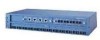
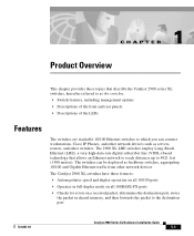
... workstations, Cisco IP Phones, and other network devices such as backbone switches, aggregating 10/100 and Gigabit Ethernet traffic from other switches. The 2900 XL LRE switches employ Long-Reach Ethernet (LRE), a very-high-data-rate digital subscriber line (VDSL)-based technology that describe the Catalyst 2900 series XL switches, hereafter referred to as the switches. • Switch features...
... workstations, Cisco IP Phones, and other network devices such as backbone switches, aggregating 10/100 and Gigabit Ethernet traffic from other switches. The 2900 XL LRE switches employ Long-Reach Ethernet (LRE), a very-high-data-rate digital subscriber line (VDSL)-based technology that describe the Catalyst 2900 series XL switches, hereafter referred to as the switches. • Switch features...
Hardware Installation Guide
Page 23
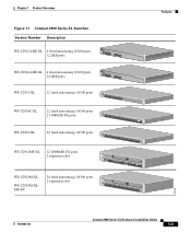
... 1 Product Overview Figure 1-1 Catalyst 2900 Series XL Switches Version Number Description WS-C2912-LRE-XL 4 fixed autosensing 10/100 ports INPUT OUTPUT PWR PWR RESET TEMP FAN 9X 10X 11X 12X 12 LRE ports Cisco RPS 300 WS-C2924-LRE-XL 4 fixed autosensing 10/100 ports 24 LRE ports INPUT OUTPUT...9X 10X 10BASE-T/100BA1S0E0-BTaXseFX 11X 12X 13X 14X 16X 17X 18X 19X 20X 21X Catalyst 2900 SERIES XL 22X 23X 24X WS-C2912MF-XL 12 100BASE-FX ports 2 expansion slots 12 1 MODE 2 3 Catalyst 2900 SERIES XL 4 5 100BASE-FX 6 7 8 9 10 11 12 WS-C2924M-XL WS-C2924M-XLEM-DC ...
... 1 Product Overview Figure 1-1 Catalyst 2900 Series XL Switches Version Number Description WS-C2912-LRE-XL 4 fixed autosensing 10/100 ports INPUT OUTPUT PWR PWR RESET TEMP FAN 9X 10X 11X 12X 12 LRE ports Cisco RPS 300 WS-C2924-LRE-XL 4 fixed autosensing 10/100 ports 24 LRE ports INPUT OUTPUT...9X 10X 10BASE-T/100BA1S0E0-BTaXseFX 11X 12X 13X 14X 16X 17X 18X 19X 20X 21X Catalyst 2900 SERIES XL 22X 23X 24X WS-C2912MF-XL 12 100BASE-FX ports 2 expansion slots 12 1 MODE 2 3 Catalyst 2900 SERIES XL 4 5 100BASE-FX 6 7 8 9 10 11 12 WS-C2924M-XL WS-C2924M-XLEM-DC ...

Hardware Installation Guide
Page 24
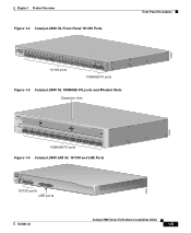
... can fully configure and monitor a standalone switch, a specific cluster member, or an entire switch cluster. Catalyst 2900 Series XL Hardware Installation Guide 1-4 78-6461-04 You can have a set of LEDs and a Mode button. All switches have up to twenty-four 10/100 ports (See Figure 1-2), up to twelve 100BASE-FX ports (See Figure 1-3), two module...
... can fully configure and monitor a standalone switch, a specific cluster member, or an entire switch cluster. Catalyst 2900 Series XL Hardware Installation Guide 1-4 78-6461-04 You can have a set of LEDs and a Mode button. All switches have up to twenty-four 10/100 ports (See Figure 1-2), up to twelve 100BASE-FX ports (See Figure 1-3), two module...
Hardware Installation Guide
Page 25
... 19X 20X 21X 22X Catalyst10209B0AS0ES-FEXRIES XL 23 24 10/100 ports 100BASE-FX ports Figure 1-3 Catalyst 2900 XL 100BASE-FX ports and Module Slots Expansion slots 47286 12 1 MODE 2 3 Catalyst 2900 SERIES XL 4 5 100BASE-FX 6 7 8 9 10 11 12 100BASE-FX ports Figure 1-4 Catalyst 2900 LRE XL 10/100 and LRE Ports INPUT OUTPUT PWR PWR RESET TEMP FAN...
... 19X 20X 21X 22X Catalyst10209B0AS0ES-FEXRIES XL 23 24 10/100 ports 100BASE-FX ports Figure 1-3 Catalyst 2900 XL 100BASE-FX ports and Module Slots Expansion slots 47286 12 1 MODE 2 3 Catalyst 2900 SERIES XL 4 5 100BASE-FX 6 7 8 9 10 11 12 100BASE-FX ports Figure 1-4 Catalyst 2900 LRE XL 10/100 and LRE Ports INPUT OUTPUT PWR PWR RESET TEMP FAN...

Hardware Installation Guide
Page 28
...is not required, a splitter is managed through the switch management interfaces. Table 1-1 Expansion Modules Module Type 10/100 Ethernet 100 BASE-FX Model Number WS-X2914-XL WS-X2914-XL-V WS-X2922-XL WS-X2922-XL-V WS-X2924-XL-V Catalyst 2900 Series XL Hardware Installation Guide 1-8 78-6461-04... 1 Product Overview (PSTN). For more information about homologated POTS splitters, contact your Cisco sales representative. Table 1-1 lists the modules that use the 0 to the PSTN. For more information about the Cisco LRE 48 POTS Splitter (PS-1M-LRE-48), refer to share lines with LRE...
...is not required, a splitter is managed through the switch management interfaces. Table 1-1 Expansion Modules Module Type 10/100 Ethernet 100 BASE-FX Model Number WS-X2914-XL WS-X2914-XL-V WS-X2922-XL WS-X2922-XL-V WS-X2924-XL-V Catalyst 2900 Series XL Hardware Installation Guide 1-8 78-6461-04... 1 Product Overview (PSTN). For more information about homologated POTS splitters, contact your Cisco sales representative. Table 1-1 lists the modules that use the 0 to the PSTN. For more information about the Cisco LRE 48 POTS Splitter (PS-1M-LRE-48), refer to share lines with LRE...

Hardware Installation Guide
Page 34
...Each of the 10/100, 100BASE-FX, and LRE ports and module slots have failed. The current bandwidth in a fault condition. Press the Standby/Active button on the Catalyst 2912 XL, 2924C XL, 2924 XL, 2924MF XL, 2924M XL, and 2924M XL DC Switches Mode LED STAT UTL FDUP 100 Port Mode Port ...is providing power to the switch (redundancy has been allocated to this device). When you change a mode, press the Mode button until the desired mode is highlighted. If it does not, the RPS fan could have a port LED. Contact Cisco Systems. The internal power supply in a switch has failed, and the RPS...
...Each of the 10/100, 100BASE-FX, and LRE ports and module slots have failed. The current bandwidth in a fault condition. Press the Standby/Active button on the Catalyst 2912 XL, 2924C XL, 2924 XL, 2924MF XL, 2924M XL, and 2924M XL DC Switches Mode LED STAT UTL FDUP 100 Port Mode Port ...is providing power to the switch (redundancy has been allocated to this device). When you change a mode, press the Mode button until the desired mode is highlighted. If it does not, the RPS fan could have a port LED. Contact Cisco Systems. The internal power supply in a switch has failed, and the RPS...

Hardware Installation Guide
Page 35
... on Catalyst 2912 LRE XL and 2924 LRE XL Switches Mode LED LRE STAT DUPLX SPEED Port Mode LRE link status Port status Port duplex mode Port speed Description Long-Reach Ethernet (LRE) link status of the 10/100 or 100BASE-FX switch ports ...or the Ethernet link status on the Catalyst 2912 LRE XL and Catalyst 2924 LRE XL switches. The default setting is auto. 78-6461-04 Catalyst 2900 Series XL Hardware Installation Guide 1-15 Default mode on all Catalyst 2900 XL and Catalyst 3500 XL switches except the Catalyst 2912 LRE XL and Catalyst 2924 LRE XL switches...
... on Catalyst 2912 LRE XL and 2924 LRE XL Switches Mode LED LRE STAT DUPLX SPEED Port Mode LRE link status Port status Port duplex mode Port speed Description Long-Reach Ethernet (LRE) link status of the 10/100 or 100BASE-FX switch ports ...or the Ethernet link status on the Catalyst 2912 LRE XL and Catalyst 2924 LRE XL switches. The default setting is auto. 78-6461-04 Catalyst 2900 Series XL Hardware Installation Guide 1-15 Default mode on all Catalyst 2900 XL and Catalyst 3500 XL switches except the Catalyst 2912 LRE XL and Catalyst 2924 LRE XL switches...
Hardware Installation Guide
Page 50
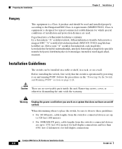
...page 2-24. Installation Guidelines The switch can be sure to observe these guidelines: • For 10/100 ports, cable lengths from the switch to connected devices are up to 328 feet (100 meters). • For 100BASE-FX ports, cable lengths from the switch to connected devices are up ...MSZEN55022). When determining where to place the switch, be installed on a table or shelf, in the "Powering On the Switch and Running POST" section on and running POST. Removing screws, cover, or otherwise dismantling the unit voids the warranty. Catalyst 2900 Series XL Hardware Installation Guide 2-6 78...
...page 2-24. Installation Guidelines The switch can be sure to observe these guidelines: • For 10/100 ports, cable lengths from the switch to connected devices are up to 328 feet (100 meters). • For 100BASE-FX ports, cable lengths from the switch to connected devices are up ...MSZEN55022). When determining where to place the switch, be installed on a table or shelf, in the "Powering On the Switch and Running POST" section on and running POST. Removing screws, cover, or otherwise dismantling the unit voids the warranty. Catalyst 2900 Series XL Hardware Installation Guide 2-6 78...

Hardware Installation Guide
Page 106
Catalyst 2900 Series XL Hardware Installation Guide B-2 78-6461...When connecting the 10/100 ports to compatible workstations, servers, routers, and Cisco IP Phones, you must use a straight-through cable wired for 10BASE-T and 100BASE-TX. (Figure B-5 shows the straight-through cable schematics.) When connecting to other switches or repeaters, you ...must use a crossover cable. (Figure B-4 shows the crossover cable schematics.) Note Use a straight-through cable to connect two ports when both ports do not have an X. 100BASE-FX Ports 100BASE-FX ports ...
Catalyst 2900 Series XL Hardware Installation Guide B-2 78-6461...When connecting the 10/100 ports to compatible workstations, servers, routers, and Cisco IP Phones, you must use a straight-through cable wired for 10BASE-T and 100BASE-TX. (Figure B-5 shows the straight-through cable schematics.) When connecting to other switches or repeaters, you ...must use a crossover cable. (Figure B-4 shows the crossover cable schematics.) Note Use a straight-through cable to connect two ports when both ports do not have an X. 100BASE-FX Ports 100BASE-FX ports ...

Hardware Installation Guide
Page 155
... B-1 connecting to 2-35 connection distances, maximum 1-6 full duplex 1-6 half duplex 1-6 pinouts B-2 100BASE-FX ports cables and connectors B-2 connecting to 2-37 to 2-38 connection distances, maximum 1-7 100 port mode LED 1-14 to 1-16 19-, 23-, and 24-inch racks 2-9 A AC power connecting...to B-2, B-4 100BASE-FX, 50/125- or 62.5/125-micron fiber-optic 2-37, B-2 crossover and straight-through pinouts B-4 RJ-21 pinouts B-5 rollover B-6 rollover pinouts DB-25 adapter B-8 CCO See Cisco.com chassis, warning against stacking C-7 circuit breaker (15A) warning C-12 Catalyst 2900 Series XL Hardware...
... B-1 connecting to 2-35 connection distances, maximum 1-6 full duplex 1-6 half duplex 1-6 pinouts B-2 100BASE-FX ports cables and connectors B-2 connecting to 2-37 to 2-38 connection distances, maximum 1-7 100 port mode LED 1-14 to 1-16 19-, 23-, and 24-inch racks 2-9 A AC power connecting...to B-2, B-4 100BASE-FX, 50/125- or 62.5/125-micron fiber-optic 2-37, B-2 crossover and straight-through pinouts B-4 RJ-21 pinouts B-5 rollover B-6 rollover pinouts DB-25 adapter B-8 CCO See Cisco.com chassis, warning against stacking C-7 circuit breaker (15A) warning C-12 Catalyst 2900 Series XL Hardware...

Hardware Installation Guide
Page 156
...Cisco.com xviii Cisco RPS See RPS CiscoWorks 2000 1-4 Class 1 laser product warning C-22 CLI 1-4 Cluster Management Suite See CMS CMS 1-4 command-line interface See CLI connecting 10/100 ports to IP Phones 2-35 to 2-36 connecting to 10/100BASE-T ports 2-35 100BASE-FX...-21 B-3 connectors, See also ports console B-5 connectors and cables 1-21 10/100BASE-T ports B-1 to B-2 100BASE-FX ports 1-7, B-2 console port 2-42 to 2-43 power (AC and RPS) 1-21 RJ-21 connector B-3 RPS ...30, C-39 default characteristics of the console port 2-42 IN-2 Catalyst 2900 Series XL Hardware Installation Guide 78-6461-04
...Cisco.com xviii Cisco RPS See RPS CiscoWorks 2000 1-4 Class 1 laser product warning C-22 CLI 1-4 Cluster Management Suite See CMS CMS 1-4 command-line interface See CLI connecting 10/100 ports to IP Phones 2-35 to 2-36 connecting to 10/100BASE-T ports 2-35 100BASE-FX...-21 B-3 connectors, See also ports console B-5 connectors and cables 1-21 10/100BASE-T ports B-1 to B-2 100BASE-FX ports 1-7, B-2 console port 2-42 to 2-43 power (AC and RPS) 1-21 RJ-21 connector B-3 RPS ...30, C-39 default characteristics of the console port 2-42 IN-2 Catalyst 2900 Series XL Hardware Installation Guide 78-6461-04
Hardware Installation Guide
Page 157
...2-6 expansion slots LEDs 1-19 supported modules 1-8 exposed wire lead warning C-41 F feedback to 2-41 78-6461-04 Catalyst 2900 Series XL Hardware Installation Guide IN-3 or 62.5/125-micron 2-37, B-2 front panel 10/100 ports 1-6 expansion slots 1-8 fixed ports 1-6 LEDs 1-9 LRE ports 1-7 full duplex 10/100BASE-T ports 1-6 to 1-7 ... brackets (telco rack-mount) 2-15 attaching mounting brackets (wall-mount) 2-22 cable guide 2-19 connecting to 10/100BASE-T ports 2-35 100BASE-FX ports 2-37 to 2-38 console port 2-42 to 2-43 LRE port 2-38 to Cisco Systems, web xviii fiber-optic cable 50/125-
...2-6 expansion slots LEDs 1-19 supported modules 1-8 exposed wire lead warning C-41 F feedback to 2-41 78-6461-04 Catalyst 2900 Series XL Hardware Installation Guide IN-3 or 62.5/125-micron 2-37, B-2 front panel 10/100 ports 1-6 expansion slots 1-8 fixed ports 1-6 LEDs 1-9 LRE ports 1-7 full duplex 10/100BASE-T ports 1-6 to 1-7 ... brackets (telco rack-mount) 2-15 attaching mounting brackets (wall-mount) 2-22 cable guide 2-19 connecting to 10/100BASE-T ports 2-35 100BASE-FX ports 2-37 to 2-38 console port 2-42 to 2-43 LRE port 2-38 to Cisco Systems, web xviii fiber-optic cable 50/125-