
Hardware Installation Guide
Page 9
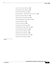
...Laser Beam Exposure Warning C-23 No On/Off Switch Warning C-24 Chassis Warning-Rack-Mounting and Servicing C-25 Reinforced Insulation Warning C-29 LAN Connections Only Warning C-30 No Field-Replaceable Units Warning C-31 Installation Warning C-32 SELV ...Source Warning C-33 Restricted Access Warning C-34 Shielded Ethernet Cables Warning C-35 Grounded Equipment Warning C-36 Ground Connection Warning C-37 Qualified Personnel Warning C-38 DC Power Disconnection Warning C-39 Exposed Wire Lead Warning C-41 Contents 78-6461-04 Catalyst...
...Laser Beam Exposure Warning C-23 No On/Off Switch Warning C-24 Chassis Warning-Rack-Mounting and Servicing C-25 Reinforced Insulation Warning C-29 LAN Connections Only Warning C-30 No Field-Replaceable Units Warning C-31 Installation Warning C-32 SELV ...Source Warning C-33 Restricted Access Warning C-34 Shielded Ethernet Cables Warning C-35 Grounded Equipment Warning C-36 Ground Connection Warning C-37 Qualified Personnel Warning C-38 DC Power Disconnection Warning C-39 Exposed Wire Lead Warning C-41 Contents 78-6461-04 Catalyst...
Hardware Installation Guide
Page 39
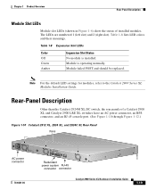
... 1-8 lists LED colors and their meanings. Rear-Panel Description Other than the Catalyst 2924M XL DC switch, the rear panels of installed modules. Module failed POST and should be replaced. Note For the default LED settings for modules, refer to the Catalyst 2900 Series XL Modules Installation Guide. Table 1-8 Expansion Slot LEDs Color Off...
... 1-8 lists LED colors and their meanings. Rear-Panel Description Other than the Catalyst 2924M XL DC switch, the rear panels of installed modules. Module failed POST and should be replaced. Note For the default LED settings for modules, refer to the Catalyst 2900 Series XL Modules Installation Guide. Table 1-8 Expansion Slot LEDs Color Off...
Hardware Installation Guide
Page 43
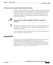
... 2-42. 78-6461-04 Catalyst 2900 Series XL Hardware Installation Guide 1-23 When the device internal power supply has been brought up or replaced, the RPS automatically stops powering the device. If more information on the Cisco RPS 300, refer to the Cisco Redundant Power System 300 Hardware... Installation Guide. Chapter 1 Product Overview Power Connectors RPS Connector on the Catalyst 2912 LRE and 2924 LRE XL Switches The RPS ...
... 2-42. 78-6461-04 Catalyst 2900 Series XL Hardware Installation Guide 1-23 When the device internal power supply has been brought up or replaced, the RPS automatically stops powering the device. If more information on the Cisco RPS 300, refer to the Cisco Redundant Power System 300 Hardware... Installation Guide. Chapter 1 Product Overview Power Connectors RPS Connector on the Catalyst 2912 LRE and 2924 LRE XL Switches The RPS ...

Hardware Installation Guide
Page 46
... ground and can cause severe bodily injury and equipment damage. Warning To prevent the switch from overheating, do not operate it in an area that is designed to install or replace this equipment. If the chassis falls, it serves as the main disconnecting device. ...its power source. Preparing for Installation Chapter 2 Installation Warning Only trained and qualified personnel should be made first and disconnected last. Catalyst 2900 Series XL Hardware Installation Guide 2-2 78-6461-04 Warning Do not stack the chassis on equipment that exceeds the maximum ...
... ground and can cause severe bodily injury and equipment damage. Warning To prevent the switch from overheating, do not operate it in an area that is designed to install or replace this equipment. If the chassis falls, it serves as the main disconnecting device. ...its power source. Preparing for Installation Chapter 2 Installation Warning Only trained and qualified personnel should be made first and disconnected last. Catalyst 2900 Series XL Hardware Installation Guide 2-2 78-6461-04 Warning Do not stack the chassis on equipment that exceeds the maximum ...

Hardware Installation Guide
Page 49
If this . The seller or buyer should be aware of the Voluntary Control Council for industrial use type. 78-6461-04 Catalyst 2900 Series XL Hardware Installation Guide 2-5 Chapter 2 Installation Preparing for Installation Japan This is used in a domestic environment, radio ...take corrective actions. 46464 Korea Warning This is a Class A Device and is registered for EMC requirements for Interference by mistake, it should be replaced with a residential-use . If this equipment is a Class A product based on the standard of this type was sold or purchased by Information ...
If this . The seller or buyer should be aware of the Voluntary Control Council for industrial use type. 78-6461-04 Catalyst 2900 Series XL Hardware Installation Guide 2-5 Chapter 2 Installation Preparing for Installation Japan This is used in a domestic environment, radio ...take corrective actions. 46464 Korea Warning This is a Class A Device and is registered for EMC requirements for Interference by mistake, it should be replaced with a residential-use . If this equipment is a Class A product based on the standard of this type was sold or purchased by Information ...

Hardware Installation Guide
Page 73
...-04 Catalyst 2900 Series XL Hardware Installation Guide 2-29 To ensure that all power is OFF, locate the circuit breaker on the panel board that power is removed from the DC circuit. Chapter 2 Installation Figure 2-20 Torquing Ground-Lug Screws Connecting to install or replace this... equipment. Warning Before performing any of the following procedures, ensure that services the DC circuit, switch the circuit breaker to the OFF position, and tape the switch handle of the circuit breaker in .) Wiring the DC-...
...-04 Catalyst 2900 Series XL Hardware Installation Guide 2-29 To ensure that all power is OFF, locate the circuit breaker on the panel board that power is removed from the DC circuit. Chapter 2 Installation Figure 2-20 Torquing Ground-Lug Screws Connecting to install or replace this... equipment. Warning Before performing any of the following procedures, ensure that services the DC circuit, switch the circuit breaker to the OFF position, and tape the switch handle of the circuit breaker in .) Wiring the DC-...

Hardware Installation Guide
Page 93
... switch and upstream network status. 78-6461-04 Catalyst 2900 Series XL Hardware Installation Guide 3-5 Amber Module Slot LED. Possible Cause Resolution Incorrect or bad cable. Module not seated in module slot. Repair cable trunking or select an alternative pair. Incorrect baud rate. Replace ...telephone cable. LRE LED not turned on the module front panel. Use the show POST EXEC command to see the "Crossover and Straight-Through Cable Pinouts" section on the Management Console. Cisco LRE CPE not communicating with a...
... switch and upstream network status. 78-6461-04 Catalyst 2900 Series XL Hardware Installation Guide 3-5 Amber Module Slot LED. Possible Cause Resolution Incorrect or bad cable. Module not seated in module slot. Repair cable trunking or select an alternative pair. Incorrect baud rate. Replace ...telephone cable. LRE LED not turned on the module front panel. Use the show POST EXEC command to see the "Crossover and Straight-Through Cable Pinouts" section on the Management Console. Cisco LRE CPE not communicating with a...