
Hardware Installation Guide
Page 9
... C-23 No On/Off Switch Warning C-24 Chassis Warning-Rack-Mounting and Servicing C-25 Reinforced Insulation Warning C-29 LAN Connections Only Warning C-30 No Field-Replaceable Units Warning C-31 Installation Warning C-32 SELV Source Warning C-33 Restricted Access Warning C-34 Shielded Ethernet Cables Warning C-35 Grounded Equipment Warning C-36 Ground Connection Warning C-37 Qualified Personnel Warning C-38 DC Power Disconnection Warning C-39...
... C-23 No On/Off Switch Warning C-24 Chassis Warning-Rack-Mounting and Servicing C-25 Reinforced Insulation Warning C-29 LAN Connections Only Warning C-30 No Field-Replaceable Units Warning C-31 Installation Warning C-32 SELV Source Warning C-33 Restricted Access Warning C-34 Shielded Ethernet Cables Warning C-35 Grounded Equipment Warning C-36 Ground Connection Warning C-37 Qualified Personnel Warning C-38 DC Power Disconnection Warning C-39...
Hardware Installation Guide
Page 11
... and performance characteristics of Catalyst 2900 series XL switches. Chapter 3, "Troubleshooting," describes how to install a switch, and provides troubleshooting information and specifications. Purpose The Catalyst 2900 Series XL Hardware Installation Guide documents the hardware features of the switches, explains how to identify and resolve some of the problems that you are familiar with the concepts and terminology of Ethernet and local area networking. Preface Audience This guide is organized into...
... and performance characteristics of Catalyst 2900 series XL switches. Chapter 3, "Troubleshooting," describes how to install a switch, and provides troubleshooting information and specifications. Purpose The Catalyst 2900 Series XL Hardware Installation Guide documents the hardware features of the switches, explains how to identify and resolve some of the problems that you are familiar with the concepts and terminology of Ethernet and local area networking. Preface Audience This guide is organized into...
Hardware Installation Guide
Page 21
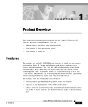
...: • Autonegotiates speed and duplex operation on all 10/100 ports • Operates in full-duplex mode on all 100BASE-FX ports • Checks for errors on a received packet, determines the destination port, stores the packet in shared memory, and then forwards the packet to the destination port 78-6461-04 Catalyst 2900 Series XL Hardware Installation Guide 1-1 The Catalyst 2900 XL switches have these topics that allows an Ethernet network to reach...
...: • Autonegotiates speed and duplex operation on all 10/100 ports • Operates in full-duplex mode on all 100BASE-FX ports • Checks for errors on a received packet, determines the destination port, stores the packet in shared memory, and then forwards the packet to the destination port 78-6461-04 Catalyst 2900 Series XL Hardware Installation Guide 1-1 The Catalyst 2900 XL switches have these topics that allows an Ethernet network to reach...
Hardware Installation Guide
Page 22
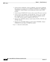
...-T, Gigabit Ethernet, and asynchronous transfer mode (ATM) modules • On the Catalyst 2924M XL DC switch, a direct current (DC) power converter • On the Catalyst 2912 LRE XL and 2924 LRE XL switches, up to 24 LRE ports through one RJ-21 connector and hot swapping capability with the Cisco LRE customer premises equipment (CPE) devices • Supports up to 2048 MAC addresses on...
...-T, Gigabit Ethernet, and asynchronous transfer mode (ATM) modules • On the Catalyst 2924M XL DC switch, a direct current (DC) power converter • On the Catalyst 2912 LRE XL and 2924 LRE XL switches, up to 24 LRE ports through one RJ-21 connector and hot swapping capability with the Cisco LRE customer premises equipment (CPE) devices • Supports up to 2048 MAC addresses on...

Hardware Installation Guide
Page 24
... control the switch and switch cluster members. The switch supports a comprehensive set of MIB extensions and four Remote Monitoring (RMON) groups. For more information about CMS, the CLI, and SNMP refer to support desktop-switching features. Front-Panel Description Chapter 1 Product Overview Management Interface Options You can configure and monitor individual switches and switch clusters by using these front-panel components. and port-level settings. • Command-line Interface (CLI)-The switch IOS CLI software is already installed on the model...
... control the switch and switch cluster members. The switch supports a comprehensive set of MIB extensions and four Remote Monitoring (RMON) groups. For more information about CMS, the CLI, and SNMP refer to support desktop-switching features. Front-Panel Description Chapter 1 Product Overview Management Interface Options You can configure and monitor individual switches and switch clusters by using these front-panel components. and port-level settings. • Command-line Interface (CLI)-The switch IOS CLI software is already installed on the model...
Hardware Installation Guide
Page 26
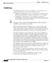
... switch, refer to operate in Appendix B, "Connectors and Cable Specifications." Unlike the 3524-PWR XL switch, the Catalyst 2900 XL switches do not provide inline power. The 10/100 switch ports can be explicitly set for Cisco IP Phones and per-port priority override. When connecting the switch to workstations, servers, routers, and Cisco IP Phones, be connected to the Catalyst 2900 Series XL and Catalyst 3500 Series XL Software Configuration Guide for 100BASE-TX traffic. These ports...
... switch, refer to operate in Appendix B, "Connectors and Cable Specifications." Unlike the 3524-PWR XL switch, the Catalyst 2900 XL switches do not provide inline power. The 10/100 switch ports can be explicitly set for Cisco IP Phones and per-port priority override. When connecting the switch to workstations, servers, routers, and Cisco IP Phones, be connected to the Catalyst 2900 Series XL and Catalyst 3500 Series XL Software Configuration Guide for 100BASE-TX traffic. These ports...
Hardware Installation Guide
Page 27
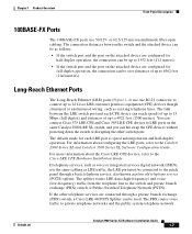
... Mbps (full duplex) and distances of up to the Catalyst 2900 Series XL and Catalyst 3500 Series XL Software Configuration Guide. The splitter routes LRE data (high-frequency) and voice (low-frequency) traffic from the telephone line to private telephone networks and the public system telephone network 78-6461-04 Catalyst 2900 Series XL Hardware Installation Guide 1-7 The default mode for full-duplex operation, the connection can be as plain old telephone service (POTS...
... Mbps (full duplex) and distances of up to the Catalyst 2900 Series XL and Catalyst 3500 Series XL Software Configuration Guide. The splitter routes LRE data (high-frequency) and voice (low-frequency) traffic from the telephone line to private telephone networks and the public system telephone network 78-6461-04 Catalyst 2900 Series XL Hardware Installation Guide 1-7 The default mode for full-duplex operation, the connection can be as plain old telephone service (POTS...

Hardware Installation Guide
Page 28
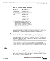
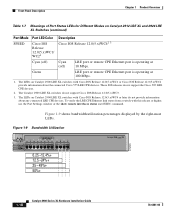
... (PBX) switch telephones that the module slots support. Due to 700 kHz frequency range. Module Slots The module slots (see Figure 1-2) are designed to the PSTN. Table 1-1 Expansion Modules Module Type 10/100 Ethernet 100 BASE-FX Model Number WS-X2914-XL WS-X2914-XL-V WS-X2922-XL WS-X2922-XL-V WS-X2924-XL-V Catalyst 2900 Series XL Hardware Installation Guide 1-8 78-6461-04 Table 1-1 lists the modules that use frequencies...
... (PBX) switch telephones that the module slots support. Due to 700 kHz frequency range. Module Slots The module slots (see Figure 1-2) are designed to the PSTN. Table 1-1 Expansion Modules Module Type 10/100 Ethernet 100 BASE-FX Model Number WS-X2914-XL WS-X2914-XL-V WS-X2922-XL WS-X2922-XL-V WS-X2924-XL-V Catalyst 2900 Series XL Hardware Installation Guide 1-8 78-6461-04 Table 1-1 lists the modules that use frequencies...
Hardware Installation Guide
Page 29
... it starts forwarding packets. Changing a port mode changes the information provided by restarting that you use the switch LEDs to 2048 MAC addresses. For a complete list and the minimum software release required, refer to select a port mode. You can use to the Release Notes for Catalyst 2900 series XL switches. LEDs 78-6461-04 You can start the module by each port LED. Refer to the Catalyst 2900 Series XL Modules Installation Guide and the Catalyst 2900 Series XL ATM Modules Installation and Configuration Guide for...
... it starts forwarding packets. Changing a port mode changes the information provided by restarting that you use the switch LEDs to 2048 MAC addresses. For a complete list and the minimum software release required, refer to select a port mode. You can use to the Release Notes for Catalyst 2900 series XL switches. LEDs 78-6461-04 You can start the module by each port LED. Refer to the Catalyst 2900 Series XL Modules Installation Guide and the Catalyst 2900 Series XL ATM Modules Installation and Configuration Guide for...
Hardware Installation Guide
Page 33
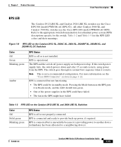
... the switch AC power supply are both powered up power, if required. Table 1-2 and Table 1-3 list the RPS LED colors and their meanings. Pressing the Mode button on the Catalyst 2912 LRE XL and 2924 LRE XL Switches Color Off Solid green Blinking green RPS Status RPS is providing power to another device (redundancy has been allocated to a neighboring device). 78-6461-04 Catalyst 2900 Series XL Hardware Installation Guide 1-13 RPS is connected...
... the switch AC power supply are both powered up power, if required. Table 1-2 and Table 1-3 list the RPS LED colors and their meanings. Pressing the Mode button on the Catalyst 2912 LRE XL and 2924 LRE XL Switches Color Off Solid green Blinking green RPS Status RPS is providing power to another device (redundancy has been allocated to a neighboring device). 78-6461-04 Catalyst 2900 Series XL Hardware Installation Guide 1-13 RPS is connected...

Hardware Installation Guide
Page 34
... in use by the switch. (See Figure 1-8.) The port duplex mode: full duplex or half duplex, and default modes: • 10/100 ports: auto • 100BaseFX ports: auto • Gigabit ports: auto The port operating speed: 10 or 100 Mbps. 1-14 Catalyst 2900 Series XL Hardware Installation Guide 78-6461-04 Port LEDs and Modes Each of the 10/100, 100BASE-FX, and LRE ports and module slots have failed. When you change a mode, press the Mode button until the desired mode is the default mode...
... in use by the switch. (See Figure 1-8.) The port duplex mode: full duplex or half duplex, and default modes: • 10/100 ports: auto • 100BaseFX ports: auto • Gigabit ports: auto The port operating speed: 10 or 100 Mbps. 1-14 Catalyst 2900 Series XL Hardware Installation Guide 78-6461-04 Port LEDs and Modes Each of the 10/100, 100BASE-FX, and LRE ports and module slots have failed. When you change a mode, press the Mode button until the desired mode is the default mode...

Hardware Installation Guide
Page 36
... Port Status LED Colors for details. Port is not forwarding. Port is operating at 100 Mbps. 1-16 Catalyst 2900 Series XL Hardware Installation Guide 78-6461-04 Port is operating in half duplex. Port was disabled by management or an address violation or was blocked by Spanning Tree Protocol (STP). See Figure 1-8 for Different Modes on a logarithmic scale. Port is transmitting or receiving data. Link present. Link fault. Note After a port is reconfigured, the port LED can affect connectivity...
... Port Status LED Colors for details. Port is not forwarding. Port is operating at 100 Mbps. 1-16 Catalyst 2900 Series XL Hardware Installation Guide 78-6461-04 Port is operating in half duplex. Port was disabled by management or an address violation or was blocked by Spanning Tree Protocol (STP). See Figure 1-8 for Different Modes on a logarithmic scale. Port is transmitting or receiving data. Link present. Link fault. Note After a port is reconfigured, the port LED can affect connectivity...

Hardware Installation Guide
Page 37
...-04 Catalyst 2900 Series XL Hardware Installation Guide 1-17 STAT Note In STAT mode, the LRE ports reflect the Ethernet link between the remote CPE and an Ethernet device such as STP checks the switch for possible loops. Cyan (off ) LRE port or remote CPE Ethernet port is operating in STP forwarding state. DUPLX Blinking amber Cisco IOS Release 12.0(5.x)WC1/ WC21 Activity on the LRE port. Green LRE link present on the LRE port. The Ethernet link default settings on...
...-04 Catalyst 2900 Series XL Hardware Installation Guide 1-17 STAT Note In STAT mode, the LRE ports reflect the Ethernet link between the remote CPE and an Ethernet device such as STP checks the switch for possible loops. Cyan (off ) LRE port or remote CPE Ethernet port is operating in STP forwarding state. DUPLX Blinking amber Cisco IOS Release 12.0(5.x)WC1/ WC21 Activity on the LRE port. Green LRE link present on the LRE port. The Ethernet link default settings on...
Hardware Installation Guide
Page 38
... CPE Ethernet link status from a switch with Cisco IOS Release 12.0(5.x)WC4 or later do not provide information about the connected Cisco 575 LRE CPE devices. Figure 1-9 shows bandwidth utilization percentages displayed by the right-most LEDs. The LEDs on Catalyst 2900 LRE XL switches with this release or higher, use the Port Settings window or the show remote interfaces status user EXEC command. These IOS releases do not support Cisco IOS...
... CPE Ethernet link status from a switch with Cisco IOS Release 12.0(5.x)WC4 or later do not provide information about the connected Cisco 575 LRE CPE devices. Figure 1-9 shows bandwidth utilization percentages displayed by the right-most LEDs. The LEDs on Catalyst 2900 LRE XL switches with this release or higher, use the Port Settings window or the show remote interfaces status user EXEC command. These IOS releases do not support Cisco IOS...
Hardware Installation Guide
Page 79
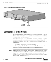
... the "Cable and Adapter Specifications" section on page B-4. 78-6461-04 Catalyst 2900 Series XL Hardware Installation Guide 2-35 Terminal block plug Tie wrap Connecting to a 10/100 Port The switch 10/100 ports configure themselves to switches or repeaters, use a crossover Category 5 cable. B +- To maximize performance, choose one of the connection. Pinouts for configuring the 10/100 Ethernet ports: • Let the ports autonegotiate both speed and duplex. • Set the port speed and duplex parameters on...
... the "Cable and Adapter Specifications" section on page B-4. 78-6461-04 Catalyst 2900 Series XL Hardware Installation Guide 2-35 Terminal block plug Tie wrap Connecting to a 10/100 Port The switch 10/100 ports configure themselves to switches or repeaters, use a crossover Category 5 cable. B +- To maximize performance, choose one of the connection. Pinouts for configuring the 10/100 Ethernet ports: • Let the ports autonegotiate both speed and duplex. • Set the port speed and duplex parameters on...
Hardware Installation Guide
Page 82
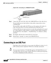
The port LED is amber while the STP discovers the topology and searches for solutions to your LRE switch, and you can hot swap the CPE devices without powering down the switch or disrupting the other switch ports. 2-38 Catalyst 2900 Series XL Hardware Installation Guide 78-6461-04 Repeat Steps 1 through a patch panel. Note You can connect both the switch and the connected device have established link. If...
The port LED is amber while the STP discovers the topology and searches for solutions to your LRE switch, and you can hot swap the CPE devices without powering down the switch or disrupting the other switch ports. 2-38 Catalyst 2900 Series XL Hardware Installation Guide 78-6461-04 Repeat Steps 1 through a patch panel. Note You can connect both the switch and the connected device have established link. If...

Hardware Installation Guide
Page 85
... switch, a Cisco LRE 48 POTS Splitter can connect directly to the Cisco LRE CPE Hardware Installation Guide. Each LRE port status LED turns on when it establishes a link with the connector and cable assembly. The PBX routes voice traffic to the switch and private branch exchange (PBX) switch or Public Switched Telephone Network (PSTN). If telephone services, such as voice or ISDN, use the same cabling as LRE traffic, the LRE port must be connected...
... switch, a Cisco LRE 48 POTS Splitter can connect directly to the Cisco LRE CPE Hardware Installation Guide. Each LRE port status LED turns on when it establishes a link with the connector and cable assembly. The PBX routes voice traffic to the switch and private branch exchange (PBX) switch or Public Switched Telephone Network (PSTN). If telephone services, such as voice or ISDN, use the same cabling as LRE traffic, the LRE port must be connected...
Hardware Installation Guide
Page 86
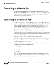
...program. See the Catalyst 2900 Series XL and Catalyst 3500 Series XL Software Configuration Guide for instructions. 2-42 Catalyst 2900 Series XL Hardware Installation Guide 78-6461-04 Follow these switch console port default characteristics: • 9600 baud • 8 data bits • 1 stop bit • No parity After you have accessed the switch, you want to connect the switch console port to its original setting. or terminal-emulation software to the switch console port. Connecting to a Module Port Chapter 2 Installation Connecting to a Module Port For information about...
...program. See the Catalyst 2900 Series XL and Catalyst 3500 Series XL Software Configuration Guide for instructions. 2-42 Catalyst 2900 Series XL Hardware Installation Guide 78-6461-04 Follow these switch console port default characteristics: • 9600 baud • 8 data bits • 1 stop bit • No parity After you have accessed the switch, you want to connect the switch console port to its original setting. or terminal-emulation software to the switch console port. Connecting to a Module Port Chapter 2 Installation Connecting to a Module Port For information about...

Hardware Installation Guide
Page 89
... Catalyst 2900 Series XL Hardware Installation Guide 3-1 See the Catalyst 2900 Series XL and Catalyst 3500 Series XL Software Configuration Guide, the Catalyst 2900 Series XL and Catalyst 3500 Series XL Command Reference, or the documentation that came with number 1x. This chapter describes these topics for ports 2x to check the most important system components before the switch begins forwarding packets. When the switch begins its POST, the port status LEDs turn amber for details. As each turn off in the power...
... Catalyst 2900 Series XL Hardware Installation Guide 3-1 See the Catalyst 2900 Series XL and Catalyst 3500 Series XL Software Configuration Guide, the Catalyst 2900 Series XL and Catalyst 3500 Series XL Command Reference, or the documentation that came with number 1x. This chapter describes these topics for ports 2x to check the most important system components before the switch begins forwarding packets. When the switch begins its POST, the port status LEDs turn amber for details. As each turn off in the power...

Hardware Installation Guide
Page 95
... and Catalyst 3500 Series XL Software Configuration Guide. • Assess possibility of improving trunk quality. Local nonstandard noise source. For more information, refer to a lower profile. Chapter 3 Troubleshooting Diagnosing Problems Table 3-2 Common Problems and Their Solutions (continued) Symptom LRE status LED stays amber. Excessive interference from other services in bundle. • Consider use of spectrally incompatible services. Consult Cisco sales representative for installation optimization. 78-6461-04 Catalyst 2900 Series XL Hardware Installation Guide...
... and Catalyst 3500 Series XL Software Configuration Guide. • Assess possibility of improving trunk quality. Local nonstandard noise source. For more information, refer to a lower profile. Chapter 3 Troubleshooting Diagnosing Problems Table 3-2 Common Problems and Their Solutions (continued) Symptom LRE status LED stays amber. Excessive interference from other services in bundle. • Consider use of spectrally incompatible services. Consult Cisco sales representative for installation optimization. 78-6461-04 Catalyst 2900 Series XL Hardware Installation Guide...


