Hardware Installation Guide
Page 9
INDEX Class 1 Laser Product Warning C-22 Laser Beam Exposure Warning C-23 No On/Off Switch Warning C-24 Chassis Warning-Rack-Mounting and Servicing C-25 Reinforced Insulation Warning C-29 LAN Connections Only Warning C-30 No Field-Replaceable Units Warning C-31 Installation Warning C-32 SELV Source Warning C-33 ... Equipment Warning C-36 Ground Connection Warning C-37 Qualified Personnel Warning C-38 DC Power Disconnection Warning C-39 Exposed Wire Lead Warning C-41 Contents 78-6461-04 Catalyst 2900 Series XL Hardware Installation Guide ix
INDEX Class 1 Laser Product Warning C-22 Laser Beam Exposure Warning C-23 No On/Off Switch Warning C-24 Chassis Warning-Rack-Mounting and Servicing C-25 Reinforced Insulation Warning C-29 LAN Connections Only Warning C-30 No Field-Replaceable Units Warning C-31 Installation Warning C-32 SELV Source Warning C-33 ... Equipment Warning C-36 Ground Connection Warning C-37 Qualified Personnel Warning C-38 DC Power Disconnection Warning C-39 Exposed Wire Lead Warning C-41 Contents 78-6461-04 Catalyst 2900 Series XL Hardware Installation Guide ix
Hardware Installation Guide
Page 52
...-head screws for attaching the brackets to the switch (19-inch rack mount) - One cable guide and one of the mounting brackets Note The cable guide does not attach to the Catalyst 2912 LRE XL and 2924 LRE XL switches. • One RJ-45-to-DB-9 adapter • Cisco Information Packet, containing warranty, safety, and support information...
...-head screws for attaching the brackets to the switch (19-inch rack mount) - One cable guide and one of the mounting brackets Note The cable guide does not attach to the Catalyst 2912 LRE XL and 2924 LRE XL switches. • One RJ-45-to-DB-9 adapter • Cisco Information Packet, containing warranty, safety, and support information...
Hardware Installation Guide
Page 53
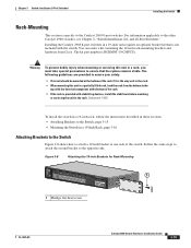
... guidelines are similar on brackets for two-rack-unit modular switches. Note Figure 2-1 shows brackets for one-rack-unit switches. 78-6461-04 Catalyst 2900 Series XL Hardware Installation Guide 2-9 Installing the Switch in a Rack Warning To prevent bodily injury when mounting or servicing this unit in a partially filled rack, load the rack from the bottom to ensure that the...
... guidelines are similar on brackets for two-rack-unit modular switches. Note Figure 2-1 shows brackets for one-rack-unit switches. 78-6461-04 Catalyst 2900 Series XL Hardware Installation Guide 2-9 Installing the Switch in a Rack Warning To prevent bodily injury when mounting or servicing this unit in a partially filled rack, load the rack from the bottom to ensure that the...
Hardware Installation Guide
Page 54
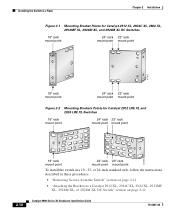
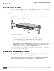
... XL, and 2924M XL DC Switches 19" rack mount point 24" rack 23" rack mount point mount point 47307 19" rack mount point 24" rack 23" rack mount point mount point Figure 2-2 Mounting Brackets Points for Catalyst 2912 LRE XL and 2924 LRE XL Switches 19" rack mount point 24" rack 23" rack mount point mount point 54725 19" rack mount point 24" rack 23" rack mount point mount point To install the switch in these procedures: • "Removing...
... XL, and 2924M XL DC Switches 19" rack mount point 24" rack 23" rack mount point mount point 47307 19" rack mount point 24" rack 23" rack mount point mount point Figure 2-2 Mounting Brackets Points for Catalyst 2912 LRE XL and 2924 LRE XL Switches 19" rack mount point 24" rack 23" rack mount point mount point 54725 19" rack mount point 24" rack 23" rack mount point mount point To install the switch in these procedures: • "Removing...
Hardware Installation Guide
Page 60
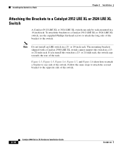
... the opposite side of the bracket to one side of the rack. To attach the brackets to a Catalyst 2912 LRE XL or 2924 LRE XL switch, use the supplied Phillips flat-head screws to a Catalyst 2912 LRE XL or 2924 LRE XL Switch A Catalyst 2912 LRE XL or 2924 LRE XL switch can only be rack-mounted in a 23-
... the opposite side of the bracket to one side of the rack. To attach the brackets to a Catalyst 2912 LRE XL or 2924 LRE XL switch, use the supplied Phillips flat-head screws to a Catalyst 2912 LRE XL or 2924 LRE XL Switch A Catalyst 2912 LRE XL or 2924 LRE XL switch can only be rack-mounted in a 23-

Hardware Installation Guide
Page 69
... .) of action. When POST completes successfully, the port LEDs return to 15 pound-force inches (lbf-in the Catalyst 2900 Series XL Installation Guide, the switch is operational. Obtain the following necessary tools and equipment: • Ratcheting torque screwdriver with a Phillips head that exerts... with the test turns amber, and the system LED turns amber. Call Cisco Systems immediately if your switch does not pass POST. As each turn off in these steps before rack-mounting and grounding the switch or wiring it to determine a course of pressure • Panduit crimping tool...
... .) of action. When POST completes successfully, the port LEDs return to 15 pound-force inches (lbf-in the Catalyst 2900 Series XL Installation Guide, the switch is operational. Obtain the following necessary tools and equipment: • Ratcheting torque screwdriver with a Phillips head that exerts... with the test turns amber, and the system LED turns amber. Call Cisco Systems immediately if your switch does not pass POST. As each turn off in these steps before rack-mounting and grounding the switch or wiring it to determine a course of pressure • Panduit crimping tool...
Hardware Installation Guide
Page 157
... (rack-mount) 2-11, 2-16 attaching mounting brackets (telco rack-mount) 2-15 attaching mounting brackets (wall-mount) 2-22 cable guide 2-19 connecting to 10/100BASE-T ports 2-35 100BASE-FX ports 2-37 to 2-38 console port 2-42 to 2-43 LRE port 2-38 to Cisco Systems, web xviii fiber-optic cable 50/125-... document conventions xii duplex SC connector B-2 E EMC regulatory statements 2-4 to 2-6 expansion slots LEDs 1-19 supported modules 1-8 exposed wire lead warning C-41 F feedback to 2-41 78-6461-04 Catalyst 2900 Series XL Hardware...
... (rack-mount) 2-11, 2-16 attaching mounting brackets (telco rack-mount) 2-15 attaching mounting brackets (wall-mount) 2-22 cable guide 2-19 connecting to 10/100BASE-T ports 2-35 100BASE-FX ports 2-37 to 2-38 console port 2-42 to 2-43 LRE port 2-38 to Cisco Systems, web xviii fiber-optic cable 50/125-... document conventions xii duplex SC connector B-2 E EMC regulatory statements 2-4 to 2-6 expansion slots LEDs 1-19 supported modules 1-8 exposed wire lead warning C-41 F feedback to 2-41 78-6461-04 Catalyst 2900 Series XL Hardware...

Hardware Installation Guide
Page 158
Index console port connecting to 2-42 to 2-43 electrical noise, avoiding 2-7 guidelines 2-6 mounting in a rack 2-18 to 2-19 mounting on a wall 2-22 to 2-24 packing list 2-7 rack-mount 2-18 to 2-19 table or shelf 2-9 wall-mount 2-22 to 2-24 warnings 2-1 to 2-4 installation guidelines 2-6 IP Phones connecting to 10/100 ports 2-35 to 2-36 J ...100 port mode 1-14 to 1-16 expansion slots 1-19 FDUP 1-14 to 1-16 full duplex 1-16 half duplex 1-16 interpreting 1-14 LRE 1-15 port (Catalyst 2900 LRE XL) 1-17 port status 1-9, 1-16 to 1-18 POST results 2-24, 3-1 RPS 1-13 to 1-14 RPS 600 1-13 SPEED 1-15 STAT...
Index console port connecting to 2-42 to 2-43 electrical noise, avoiding 2-7 guidelines 2-6 mounting in a rack 2-18 to 2-19 mounting on a wall 2-22 to 2-24 packing list 2-7 rack-mount 2-18 to 2-19 table or shelf 2-9 wall-mount 2-22 to 2-24 warnings 2-1 to 2-4 installation guidelines 2-6 IP Phones connecting to 10/100 ports 2-35 to 2-36 J ...100 port mode 1-14 to 1-16 expansion slots 1-19 FDUP 1-14 to 1-16 full duplex 1-16 half duplex 1-16 interpreting 1-14 LRE 1-15 port (Catalyst 2900 LRE XL) 1-17 port status 1-9, 1-16 to 1-18 POST results 2-24, 3-1 RPS 1-13 to 1-14 RPS 600 1-13 SPEED 1-15 STAT...
Hardware Installation Guide
Page 159
mid-mount See installation attaching mounting brackets (telco rack-mount) modules 1-8 mounting brackets 2-9 attaching 2-11, 2-15, 2-22 N no on/off switch warning C-24 O overtemperature warning C-9 P PC, connecting to switch 2-42 performance problems, solving 3-3 personnel warning C-3 pinouts 10/100BASE-T ports B-2... cable, straight-through and crossover B-4 RJ-21 connector B-5 RJ-45-to-DB-25 terminal adapter B-8 RJ-45-to-DB-9 terminal adapter B-7 rollover cable B-7, B-8 Index port LEDs Catalyst ...
mid-mount See installation attaching mounting brackets (telco rack-mount) modules 1-8 mounting brackets 2-9 attaching 2-11, 2-15, 2-22 N no on/off switch warning C-24 O overtemperature warning C-9 P PC, connecting to switch 2-42 performance problems, solving 3-3 personnel warning C-3 pinouts 10/100BASE-T ports B-2... cable, straight-through and crossover B-4 RJ-21 connector B-5 RJ-45-to-DB-25 terminal adapter B-8 RJ-45-to-DB-9 terminal adapter B-7 rollover cable B-7, B-8 Index port LEDs Catalyst ...

Hardware Installation Guide
Page 4
... 3-5 Tools and Equipment 3-5 Verifying Switch Operation 3-5 Installing the Switch 3-5 Catalyst 2960 Switch Hardware Installation Guide iv OL-7075-09 and 48-Port Switches) 2-1 Preparing for Installation 2-1 Warnings 2-2 Guidelines for Particulate Matter 2-4 Installation Guidelines 2-4 Box Contents 2-5 Tools and Equipment 2-5 Verifying Switch Operation 2-5 Installing the Switch 2-6 Rack-Mounting 2-6 Removing Screws from the Switch 2-7 Attaching Brackets to the Catalyst 2960 Switch 2-7 Mounting the Switch in a Rack 2-10 Attaching the Cable...
... 3-5 Tools and Equipment 3-5 Verifying Switch Operation 3-5 Installing the Switch 3-5 Catalyst 2960 Switch Hardware Installation Guide iv OL-7075-09 and 48-Port Switches) 2-1 Preparing for Installation 2-1 Warnings 2-2 Guidelines for Particulate Matter 2-4 Installation Guidelines 2-4 Box Contents 2-5 Tools and Equipment 2-5 Verifying Switch Operation 2-5 Installing the Switch 2-6 Rack-Mounting 2-6 Removing Screws from the Switch 2-7 Attaching Brackets to the Catalyst 2960 Switch 2-7 Mounting the Switch in a Rack 2-10 Attaching the Cable...

Hardware Installation Guide
Page 5
... Module Ports B-3 Dual-Purpose Ports B-3 Catalyst 2960 Switch Hardware Installation Guide v and 100BASE-TX-Compatible Devices B-1 Connecting to 10BASE-T- or Shelf-Mounting (with Mounting Screws) 3-8 Wall-Mounting (with Mounting Screws) 3-11 Magnet Mounting 3-14 Rack-Mounting 3-15 Attaching Brackets to the Switch 3-15 Mounting the Switch in a 19-Inch Rack 3-16 Wall-Mounting (with Mounting Screws) 3-7 Under the Desk- or Shelf-Mounting (without Mounting Screws) 3-6 Desk- Contents 4 C H A P T E R A A P P E N D I X B A P P E N D I X OL...
... Module Ports B-3 Dual-Purpose Ports B-3 Catalyst 2960 Switch Hardware Installation Guide v and 100BASE-TX-Compatible Devices B-1 Connecting to 10BASE-T- or Shelf-Mounting (with Mounting Screws) 3-8 Wall-Mounting (with Mounting Screws) 3-11 Magnet Mounting 3-14 Rack-Mounting 3-15 Attaching Brackets to the Switch 3-15 Mounting the Switch in a 19-Inch Rack 3-16 Wall-Mounting (with Mounting Screws) 3-7 Under the Desk- or Shelf-Mounting (without Mounting Screws) 3-6 Desk- Contents 4 C H A P T E R A A P P E N D I X B A P P E N D I X OL...
Hardware Installation Guide
Page 37
...switch and the RPS to rack-mount the switch. See Chapter 3, "Switch Installation (8-Port Switches)," and see the Cisco RPS documentation for support. Note When you should insert a 5-decibel (dB) or 10-dB inline optical attenuator between the fiber-optic cable plant and the receiving port on Cisco.com describes the box contents. OL-7075-09 Catalyst 2960 Switch... Hardware Installation Guide 2-5 Access to an AC power outlet. Box Contents The switch getting started guide on the ...
...switch and the RPS to rack-mount the switch. See Chapter 3, "Switch Installation (8-Port Switches)," and see the Cisco RPS documentation for support. Note When you should insert a 5-decibel (dB) or 10-dB inline optical attenuator between the fiber-optic cable plant and the receiving port on Cisco.com describes the box contents. OL-7075-09 Catalyst 2960 Switch... Hardware Installation Guide 2-5 Access to an AC power outlet. Box Contents The switch getting started guide on the ...

Hardware Installation Guide
Page 38
... procedures: • Rack-Mounting, page 2-6 • Wall-Mounting, page 2-11 • Table- and 48-port switches. Statement 1006 Catalyst 2960 Switch Hardware Installation Guide 2-6 OL-7075-09 Installing the Switch Chapter 2 Switch Installation (24- Statement 370 As the switch powers on page 2-6. The RPS LED remains green for some time and then reflects the switch operating status. Call Cisco technical support representative...
... procedures: • Rack-Mounting, page 2-6 • Wall-Mounting, page 2-11 • Table- and 48-port switches. Statement 1006 Catalyst 2960 Switch Hardware Installation Guide 2-6 OL-7075-09 Installing the Switch Chapter 2 Switch Installation (24- Statement 370 As the switch powers on page 2-6. The RPS LED remains green for some time and then reflects the switch operating status. Call Cisco technical support representative...

Hardware Installation Guide
Page 39
... you can order a kit that contains the 24-inch rack-mounting brackets and hardware from Cisco by using part number RCKMNT-1RU=. Follow the same steps to attach the second bracket to one side of the switch. Figure 2-1 shows how to the Catalyst 2960 Switch, page 2-7 • Mounting the Switch in a Rack, page 2-10 • Attaching the Cable Guide, page...
... you can order a kit that contains the 24-inch rack-mounting brackets and hardware from Cisco by using part number RCKMNT-1RU=. Follow the same steps to attach the second bracket to one side of the switch. Figure 2-1 shows how to the Catalyst 2960 Switch, page 2-7 • Mounting the Switch in a Rack, page 2-10 • Attaching the Cable Guide, page...
Hardware Installation Guide
Page 59
... remain solid green. For information applicable to rack-mount the switch. This section describes these installation procedures: • Desk- or Shelf-Mounting (without Mounting Screws), page 3-6 • Desk- The kit part number is specific to the Catalyst 2960 8-port switches. LEDs can receive power from Cisco. Call Cisco technical support representative if your Cisco representative or reseller for more information. You...
... remain solid green. For information applicable to rack-mount the switch. This section describes these installation procedures: • Desk- or Shelf-Mounting (without Mounting Screws), page 3-6 • Desk- The kit part number is specific to the Catalyst 2960 8-port switches. LEDs can receive power from Cisco. Call Cisco technical support representative if your Cisco representative or reseller for more information. You...

Hardware Installation Guide
Page 60
...Remove the four rubber feet from sliding on page 2-20 to use the mounting screws, follow these tasks to the Catalyst 2960 8-port switches. Connect to the front-panel ports. For configuration instructions about using the ...Catalyst 2960 Switch Hardware Installation Guide 3-6 OL-7075-09 See the switch getting started guide for instructions. 3. Connect to a 10/100 or 10/100/1000 port, and run Express Setup. Installing the Switch Chapter 3 Switch Installation (8-Port Switches) • Under the Desk- The switch can be installed on the top of a desk or shelf with Rack-Mount...
...Remove the four rubber feet from sliding on page 2-20 to use the mounting screws, follow these tasks to the Catalyst 2960 8-port switches. Connect to the front-panel ports. For configuration instructions about using the ...Catalyst 2960 Switch Hardware Installation Guide 3-6 OL-7075-09 See the switch getting started guide for instructions. 3. Connect to a 10/100 or 10/100/1000 port, and run Express Setup. Installing the Switch Chapter 3 Switch Installation (8-Port Switches) • Under the Desk- The switch can be installed on the top of a desk or shelf with Rack-Mount...
Hardware Installation Guide
Page 69
... Brackets to the Switch, page 3-15 • Mounting the Switch in a 19-Inch Rack, page 3-16 Attaching Brackets to the Switch Figure 3-8 shows how to attach a 19-inch bracket to the other Catalyst 2960 switches, see Chapter 2, "Switch Installation (24- Warning To prevent bodily injury when mounting or servicing this unit in a partially filled rack, load the rack from Cisco. The kit part...
... Brackets to the Switch, page 3-15 • Mounting the Switch in a 19-Inch Rack, page 3-16 Attaching Brackets to the Switch Figure 3-8 shows how to attach a 19-inch bracket to the other Catalyst 2960 switches, see Chapter 2, "Switch Installation (24- Warning To prevent bodily injury when mounting or servicing this unit in a partially filled rack, load the rack from Cisco. The kit part...
Hardware Installation Guide
Page 70
... CLI-Based Setup Program." You can order a kit containing the 19-inch rack-mounting brackets and hardware from Cisco. The kit part number is specific to the Catalyst 2960 8-port switches. Connect to the other Catalyst 2960 switches, see Chapter 2, "Switch Installation (24- Figure 3-9 Mounting the Switch in a 19-Inch Rack SYST STAT DPLX SPD MODE CONSOLE 1x 2x 3x 4x 5x 6x...
... CLI-Based Setup Program." You can order a kit containing the 19-inch rack-mounting brackets and hardware from Cisco. The kit part number is specific to the Catalyst 2960 8-port switches. Connect to the other Catalyst 2960 switches, see Chapter 2, "Switch Installation (24- Figure 3-9 Mounting the Switch in a 19-Inch Rack SYST STAT DPLX SPD MODE CONSOLE 1x 2x 3x 4x 5x 6x...
Hardware Installation Guide
Page 105
... 1-22 to a power source C-4 mounting in a rack (8-port switches) 3-15 to 3-16 on a wall (24- Index G ground connection warning 2-4, 3-3 grounded equipment warning 2-3, 3-3 H HP OpenView 1-22 humidity, relative A-1 I installation assigning the IP address C-4 connecting to configure switch 2-21, 3-18 network configuration examples 1-1 noise, electrical 2-5, 3-4 no user-serviceable parts warning 2-4 O overheating warning 2-2, 3-1 Catalyst 2960 Switch Hardware Installation Guide IN...
... 1-22 to a power source C-4 mounting in a rack (8-port switches) 3-15 to 3-16 on a wall (24- Index G ground connection warning 2-4, 3-3 grounded equipment warning 2-3, 3-3 H HP OpenView 1-22 humidity, relative A-1 I installation assigning the IP address C-4 connecting to configure switch 2-21, 3-18 network configuration examples 1-1 noise, electrical 2-5, 3-4 no user-serviceable parts warning 2-4 O overheating warning 2-2, 3-1 Catalyst 2960 Switch Hardware Installation Guide IN...
Hardware Installation Guide
Page 106
... 4-1, C-4 running at power on 2-6, 3-5, 4-2 power connecting to 2-5, 3-5 connectors 1-19, 1-20 power on 2-5, 3-5 IN-4 Catalyst 2960 Switch Hardware Installation Guide power-on self test See POST Power over Ethernet See PoE Power over Ethernet See PoE power supply AC power outlet ...the Catalyst 2960PD-8TT-L switch 1-13 internal 1-20 RPS connector 1-20 power supply warning 2-3, 3-3 procedures connection 2-14 to 2-20 installation 2-6 to 2-14, 3-5 to 3-18 product disposal warning 2-3, 3-3 R rack-mounting 2-7 to 2-10, 3-15 to 3-16 rack-mounting warning 2-3, 2-6, 3-2, 3-15 read the wall-mounting ...
... 4-1, C-4 running at power on 2-6, 3-5, 4-2 power connecting to 2-5, 3-5 connectors 1-19, 1-20 power on 2-5, 3-5 IN-4 Catalyst 2960 Switch Hardware Installation Guide power-on self test See POST Power over Ethernet See PoE Power over Ethernet See PoE power supply AC power outlet ...the Catalyst 2960PD-8TT-L switch 1-13 internal 1-20 RPS connector 1-20 power supply warning 2-3, 3-3 procedures connection 2-14 to 2-20 installation 2-6 to 2-14, 3-5 to 3-18 product disposal warning 2-3, 3-3 R rack-mounting 2-7 to 2-10, 3-15 to 3-16 rack-mounting warning 2-3, 2-6, 3-2, 3-15 read the wall-mounting ...