Hardware Installation Guide
Page 6
... Power Connectors 1-21 Internal Power Supply Connector 1-21 DC Power Connector 1-21 Cisco RPS Connector 1-22 Console Port 1-23 2 C H A P T E R Installation 2-1 Preparing for Installation 2-1 Warnings 2-1 EMC Regulatory Statements 2-4 U.S.A. 2-4 Taiwan 2-4 Japan 2-5 Korea 2-5 Hungary 2-6 Installation Guidelines 2-6 Verifying Package Contents 2-7 Installing the Switch on a Table or Shelf 2-9 Installing the Switch in a Rack 2-9 Removing Screws from the Switch 2-11 Attaching the Brackets to a Catalyst...
... Power Connectors 1-21 Internal Power Supply Connector 1-21 DC Power Connector 1-21 Cisco RPS Connector 1-22 Console Port 1-23 2 C H A P T E R Installation 2-1 Preparing for Installation 2-1 Warnings 2-1 EMC Regulatory Statements 2-4 U.S.A. 2-4 Taiwan 2-4 Japan 2-5 Korea 2-5 Hungary 2-6 Installation Guidelines 2-6 Verifying Package Contents 2-7 Installing the Switch on a Table or Shelf 2-9 Installing the Switch in a Rack 2-9 Removing Screws from the Switch 2-11 Attaching the Brackets to a Catalyst...
Hardware Installation Guide
Page 8
... Identifying a Rollover Cable B-6 Connecting to a PC B-6 Connecting to a Terminal B-7 Translated Safety Warnings C-1 Attaching the Cisco RPS (model PWR600-AC-RPS) C-1 Attaching the Cisco RPS (model PWR300-AC-RPS-N1) C-2 Qualified Personnel Warning C-3 Installation Warning C-4 Jewelry Removal Warning C-5 Stacking the... C-9 TN Power Warning C-10 Ground Connection Warning C-11 Circuit Breaker (15A) Warning C-12 Grounded Equipment Warning C-14 Supply Circuit Warning C-15 Voltage Warning C-16 Power Supply Warning C-17 Lightning Activity Warning C-19 Product Disposal Warning C-21 Catalyst 2900 Series ...
... Identifying a Rollover Cable B-6 Connecting to a PC B-6 Connecting to a Terminal B-7 Translated Safety Warnings C-1 Attaching the Cisco RPS (model PWR600-AC-RPS) C-1 Attaching the Cisco RPS (model PWR300-AC-RPS-N1) C-2 Qualified Personnel Warning C-3 Installation Warning C-4 Jewelry Removal Warning C-5 Stacking the... C-9 TN Power Warning C-10 Ground Connection Warning C-11 Circuit Breaker (15A) Warning C-12 Grounded Equipment Warning C-14 Supply Circuit Warning C-15 Voltage Warning C-16 Power Supply Warning C-17 Lightning Activity Warning C-19 Product Disposal Warning C-21 Catalyst 2900 Series ...
Hardware Installation Guide
Page 33
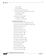
...) descriptions specific for the switch. The RPS and the switch AC power supply are both powered up power, if required. If the switch power supply fails, the switch powers down and after 15 seconds restarts, using power from the RPS. Chapter 1 Product Overview Front-Panel Description RPS LED The Catalyst 2912 LRE XL and Catalyst 2924 LRE XL switches use the Cisco RPS 600 (model PWR600...
...) descriptions specific for the switch. The RPS and the switch AC power supply are both powered up power, if required. If the switch power supply fails, the switch powers down and after 15 seconds restarts, using power from the RPS. Chapter 1 Product Overview Front-Panel Description RPS LED The Catalyst 2912 LRE XL and Catalyst 2924 LRE XL switches use the Cisco RPS 600 (model PWR600...

Hardware Installation Guide
Page 34
... mode. Table 1-6 and Table 1-7 list the port LED colors. Port LEDs and Modes Each of information displayed. Contact Cisco Systems. The internal power supply in use by the switch. (See Figure 1-8.) The port duplex mode: full duplex or half duplex, and default modes: • 10/100 ...Gigabit ports: auto The port operating speed: 10 or 100 Mbps. 1-14 Catalyst 2900 Series XL Hardware Installation Guide 78-6461-04 These port LEDs, as a group or individually, display information about the switch and about the individual ports. Front-Panel Description Chapter 1 Product Overview Table...
... mode. Table 1-6 and Table 1-7 list the port LED colors. Port LEDs and Modes Each of information displayed. Contact Cisco Systems. The internal power supply in use by the switch. (See Figure 1-8.) The port duplex mode: full duplex or half duplex, and default modes: • 10/100 ...Gigabit ports: auto The port operating speed: 10 or 100 Mbps. 1-14 Catalyst 2900 Series XL Hardware Installation Guide 78-6461-04 These port LEDs, as a group or individually, display information about the switch and about the individual ports. Front-Panel Description Chapter 1 Product Overview Table...
Hardware Installation Guide
Page 41
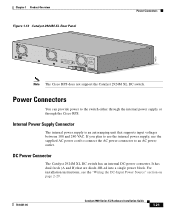
... plan to use the internal power supply, use the supplied AC power cord to connect the AC power connector to the switch either through the internal power supply or through the Cisco RPS. Internal Power Supply Connector The internal power supply is an autoranging unit that are diode-OR-ed into a single power block. DC Power Connector The Catalyst 2924M XL DC switch has an internal DC...
... plan to use the internal power supply, use the supplied AC power cord to connect the AC power connector to the switch either through the internal power supply or through the Cisco RPS. Internal Power Supply Connector The internal power supply is an autoranging unit that are diode-OR-ed into a single power block. DC Power Connector The Catalyst 2924M XL DC switch has an internal DC...
Hardware Installation Guide
Page 42
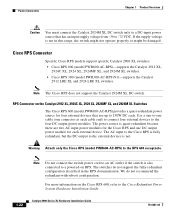
... supply voltage from -36 to a powered-on the Catalyst 2912 XL, 2924C XL, 2924 XL, 2924MF XL, and 2924M XL Switches The Cisco RPS 600 (model PWR600-AC-RPS) provides a quasi-redundant power source for the Cisco RPS and one connector at each . RPS Connector on RPS. Cisco RPS Connector Specific Cisco RPS models support specific Catalyst 2900 XL switches: • Cisco...
... supply voltage from -36 to a powered-on the Catalyst 2912 XL, 2924C XL, 2924 XL, 2924MF XL, and 2924M XL Switches The Cisco RPS 600 (model PWR600-AC-RPS) provides a quasi-redundant power source for the Cisco RPS and one connector at each . RPS Connector on RPS. Cisco RPS Connector Specific Cisco RPS models support specific Catalyst 2900 XL switches: • Cisco...
Hardware Installation Guide
Page 43
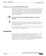
... the Console Port" section on the Cisco RPS 300, refer to the Cisco Redundant Power System 300 Hardware Installation Guide. It automatically senses when the power supply of network traffic. If more information on page 2-42. 78-6461-04 Catalyst 2900 Series XL Hardware Installation Guide 1-23 You can only power one switch fails at a time. For more...
... the Console Port" section on the Cisco RPS 300, refer to the Cisco Redundant Power System 300 Hardware Installation Guide. It automatically senses when the power supply of network traffic. If more information on page 2-42. 78-6461-04 Catalyst 2900 Series XL Hardware Installation Guide 1-23 You can only power one switch fails at a time. For more...

Hardware Installation Guide
Page 47
... Installation Warning This product relies on the phase conductors (all national laws and regulations. 78-6461-04 Catalyst 2900 Series XL Hardware Installation Guide 2-3 For systems without a power switch, line voltages are present within the power supply when the power cord is connected. Warning A voltage mismatch can cause equipment damage and may pose a fire hazard. Warning...
... Installation Warning This product relies on the phase conductors (all national laws and regulations. 78-6461-04 Catalyst 2900 Series XL Hardware Installation Guide 2-3 For systems without a power switch, line voltages are present within the power supply when the power cord is connected. Warning A voltage mismatch can cause equipment damage and may pose a fire hazard. Warning...
Hardware Installation Guide
Page 53
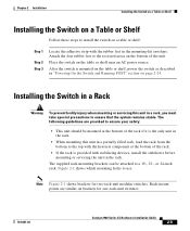
... ensure your safety: • This unit should be attached to a 19-, 23-, or 24-inch rack. After the switch is mounted on the table or shelf, power the switch as described in the mounting-kit envelope. The supplied rack-mounting brackets can be mounted at the bottom of the unit. Place the... unit in a rack, you must take special precautions to ensure that the system remains stable. Note Figure 2-1 shows brackets for one-rack-unit switches. 78-6461-04 Catalyst 2900 Series XL Hardware Installation Guide 2-9 The following guidelines are similar on brackets for two-rack-unit modular...
... ensure your safety: • This unit should be attached to a 19-, 23-, or 24-inch rack. After the switch is mounted on the table or shelf, power the switch as described in the mounting-kit envelope. The supplied rack-mounting brackets can be mounted at the bottom of the unit. Place the... unit in a rack, you must take special precautions to ensure that the system remains stable. Note Figure 2-1 shows brackets for one-rack-unit switches. 78-6461-04 Catalyst 2900 Series XL Hardware Installation Guide 2-9 The following guidelines are similar on brackets for two-rack-unit modular...
Hardware Installation Guide
Page 63
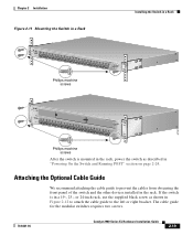
... Phillips machine screws After the switch is in a 19-, 23-, or 24-inch rack, use the supplied black screw as described in the rack. The cable guide for the modular switches requires two screws. 78-6461-04 Catalyst 2900 Series XL Hardware Installation Guide... 2-19 Attaching the Optional Cable Guide We recommend attaching the cable guide to the left or right bracket. If the switch is mounted in the rack, power...
... Phillips machine screws After the switch is in a 19-, 23-, or 24-inch rack, use the supplied black screw as described in the rack. The cable guide for the modular switches requires two screws. 78-6461-04 Catalyst 2900 Series XL Hardware Installation Guide... 2-19 Attaching the Optional Cable Guide We recommend attaching the cable guide to the left or right bracket. If the switch is mounted in the rack, power...
Hardware Installation Guide
Page 68
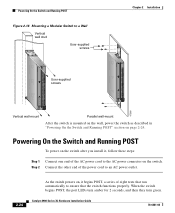
... for 2 seconds, and then they turn green. Powering On the Switch and Running POST To power on the switch after you install it begins POST, a series of the AC power cord to the AC power connector on page 2-24. Catalyst 2900 Series XL Hardware Installation Guide 78-6461-04 ...SERIES 16x 17x 18x 19x 20x 21x 22x 23x 24x Powering On the Switch and Running POST Figure 2-16 Mounting a Modular Switch to a Wall Vertical wall stud User-supplied screws User-supplied...
... for 2 seconds, and then they turn green. Powering On the Switch and Running POST To power on the switch after you install it begins POST, a series of the AC power cord to the AC power connector on page 2-24. Catalyst 2900 Series XL Hardware Installation Guide 78-6461-04 ...SERIES 16x 17x 18x 19x 20x 21x 22x 23x 24x Powering On the Switch and Running POST Figure 2-16 Mounting a Modular Switch to a Wall Vertical wall stud User-supplied screws User-supplied...
Hardware Installation Guide
Page 159
... (telco rack-mount) modules 1-8 mounting brackets 2-9 attaching 2-11, 2-15, 2-22 N no on/off switch warning C-24 O overtemperature warning C-9 P PC, connecting to switch 2-42 performance problems, solving 3-3 personnel warning C-3 pinouts 10/100BASE-T ports B-2 cable, straight-through and crossover...16 to 1-18 POST results 2-24 power connecting to 2-24 warning C-15 power connectors 1-21 power on 2-24 power supply AC power outlet 1-21 RPS connector 1-21 warning C-17 product disposal warning C-21 Q qualified personnel warning C-3 78-6461-04 Catalyst 2900 Series XL Hardware Installation Guide ...
... (telco rack-mount) modules 1-8 mounting brackets 2-9 attaching 2-11, 2-15, 2-22 N no on/off switch warning C-24 O overtemperature warning C-9 P PC, connecting to switch 2-42 performance problems, solving 3-3 personnel warning C-3 pinouts 10/100BASE-T ports B-2 cable, straight-through and crossover...16 to 1-18 POST results 2-24 power connecting to 2-24 warning C-15 power connectors 1-21 power on 2-24 power supply AC power outlet 1-21 RPS connector 1-21 warning C-17 product disposal warning C-21 Q qualified personnel warning C-3 78-6461-04 Catalyst 2900 Series XL Hardware Installation Guide ...

Hardware Installation Guide
Page 160
... cables straight-through B-4 SunNet Manager 1-4 supply circuit warning C-15 switch powering on 2-24 switched ports, module 1-8 System LED 1-12 T telco racks 2-15 telephone network power warning See TN power warning C-10 temperature maximum for installation 2-7, A-2 warning C-9 temperature warning C-9 terminal, connecting to switch 2-42 terminal adapter pinouts RH-45-to-RJ-45 B-7 IN-6 Catalyst 2900 Series XL Hardware Installation...
... cables straight-through B-4 SunNet Manager 1-4 supply circuit warning C-15 switch powering on 2-24 switched ports, module 1-8 System LED 1-12 T telco racks 2-15 telephone network power warning See TN power warning C-10 temperature maximum for installation 2-7, A-2 warning C-9 temperature warning C-9 terminal, connecting to switch 2-42 terminal adapter pinouts RH-45-to-RJ-45 B-7 IN-6 Catalyst 2900 Series XL Hardware Installation...

